EP0122816A2 - Einstellung der optischen Fokussierung bei einem optischen Speicherverfahren - Google Patents
Einstellung der optischen Fokussierung bei einem optischen Speicherverfahren Download PDFInfo
- Publication number
- EP0122816A2 EP0122816A2 EP84302661A EP84302661A EP0122816A2 EP 0122816 A2 EP0122816 A2 EP 0122816A2 EP 84302661 A EP84302661 A EP 84302661A EP 84302661 A EP84302661 A EP 84302661A EP 0122816 A2 EP0122816 A2 EP 0122816A2
- Authority
- EP
- European Patent Office
- Prior art keywords
- tracking
- optical
- control device
- focus position
- parallel
- Prior art date
- Legal status (The legal status is an assumption and is not a legal conclusion. Google has not performed a legal analysis and makes no representation as to the accuracy of the status listed.)
- Granted
Links
- 230000003287 optical effect Effects 0.000 title claims abstract description 98
- 229920001971 elastomer Polymers 0.000 claims description 12
- 229910052751 metal Inorganic materials 0.000 claims description 9
- 239000002184 metal Substances 0.000 claims description 9
- 239000005977 Ethylene Substances 0.000 claims description 6
- 229910045601 alloy Inorganic materials 0.000 claims description 3
- 239000000956 alloy Substances 0.000 claims description 3
- 230000007246 mechanism Effects 0.000 abstract description 14
- 230000005389 magnetism Effects 0.000 description 19
- 238000006073 displacement reaction Methods 0.000 description 12
- 238000013016 damping Methods 0.000 description 10
- 230000002411 adverse Effects 0.000 description 8
- 238000010276 construction Methods 0.000 description 7
- 239000000463 material Substances 0.000 description 5
- 229920005549 butyl rubber Polymers 0.000 description 4
- 230000003247 decreasing effect Effects 0.000 description 4
- 230000006872 improvement Effects 0.000 description 4
- 239000013013 elastic material Substances 0.000 description 3
- 230000004907 flux Effects 0.000 description 3
- 230000001678 irradiating effect Effects 0.000 description 3
- 229910000881 Cu alloy Inorganic materials 0.000 description 2
- 239000000853 adhesive Substances 0.000 description 2
- 230000001070 adhesive effect Effects 0.000 description 2
- 230000002301 combined effect Effects 0.000 description 2
- 238000010586 diagram Methods 0.000 description 2
- 230000000694 effects Effects 0.000 description 2
- 230000005288 electromagnetic effect Effects 0.000 description 2
- 238000005187 foaming Methods 0.000 description 2
- 230000005484 gravity Effects 0.000 description 2
- 230000004048 modification Effects 0.000 description 2
- 238000012986 modification Methods 0.000 description 2
- 229920002635 polyurethane Polymers 0.000 description 2
- 239000004814 polyurethane Substances 0.000 description 2
- 229920002379 silicone rubber Polymers 0.000 description 2
- 229920003002 synthetic resin Polymers 0.000 description 2
- 239000000057 synthetic resin Substances 0.000 description 2
- 229910000838 Al alloy Inorganic materials 0.000 description 1
- 206010010071 Coma Diseases 0.000 description 1
- 229910000861 Mg alloy Inorganic materials 0.000 description 1
- 229920000297 Rayon Polymers 0.000 description 1
- XUIMIQQOPSSXEZ-UHFFFAOYSA-N Silicon Chemical compound [Si] XUIMIQQOPSSXEZ-UHFFFAOYSA-N 0.000 description 1
- 230000004075 alteration Effects 0.000 description 1
- DMFGNRRURHSENX-UHFFFAOYSA-N beryllium copper Chemical compound [Be].[Cu] DMFGNRRURHSENX-UHFFFAOYSA-N 0.000 description 1
- HPDFFVBPXCTEDN-UHFFFAOYSA-N copper manganese Chemical compound [Mn].[Cu] HPDFFVBPXCTEDN-UHFFFAOYSA-N 0.000 description 1
- 230000003111 delayed effect Effects 0.000 description 1
- 238000009795 derivation Methods 0.000 description 1
- 230000009977 dual effect Effects 0.000 description 1
- 239000012530 fluid Substances 0.000 description 1
- 239000004519 grease Substances 0.000 description 1
- 229910001000 nickel titanium Inorganic materials 0.000 description 1
- 230000002093 peripheral effect Effects 0.000 description 1
- 229910052710 silicon Inorganic materials 0.000 description 1
- 239000010703 silicon Substances 0.000 description 1
Images

Classifications
-
- G—PHYSICS
- G11—INFORMATION STORAGE
- G11B—INFORMATION STORAGE BASED ON RELATIVE MOVEMENT BETWEEN RECORD CARRIER AND TRANSDUCER
- G11B7/00—Recording or reproducing by optical means, e.g. recording using a thermal beam of optical radiation by modifying optical properties or the physical structure, reproducing using an optical beam at lower power by sensing optical properties; Record carriers therefor
- G11B7/08—Disposition or mounting of heads or light sources relatively to record carriers
- G11B7/09—Disposition or mounting of heads or light sources relatively to record carriers with provision for moving the light beam or focus plane for the purpose of maintaining alignment of the light beam relative to the record carrier during transducing operation, e.g. to compensate for surface irregularities of the latter or for track following
- G11B7/0925—Electromechanical actuators for lens positioning
- G11B7/0932—Details of sprung supports
-
- G—PHYSICS
- G11—INFORMATION STORAGE
- G11B—INFORMATION STORAGE BASED ON RELATIVE MOVEMENT BETWEEN RECORD CARRIER AND TRANSDUCER
- G11B11/00—Recording on or reproducing from the same record carrier wherein for these two operations the methods are covered by different main groups of groups G11B3/00 - G11B7/00 or by different subgroups of group G11B9/00; Record carriers therefor
- G11B11/10—Recording on or reproducing from the same record carrier wherein for these two operations the methods are covered by different main groups of groups G11B3/00 - G11B7/00 or by different subgroups of group G11B9/00; Record carriers therefor using recording by magnetic means or other means for magnetisation or demagnetisation of a record carrier, e.g. light induced spin magnetisation; Demagnetisation by thermal or stress means in the presence or not of an orienting magnetic field
- G11B11/105—Recording on or reproducing from the same record carrier wherein for these two operations the methods are covered by different main groups of groups G11B3/00 - G11B7/00 or by different subgroups of group G11B9/00; Record carriers therefor using recording by magnetic means or other means for magnetisation or demagnetisation of a record carrier, e.g. light induced spin magnetisation; Demagnetisation by thermal or stress means in the presence or not of an orienting magnetic field using a beam of light or a magnetic field for recording by change of magnetisation and a beam of light for reproducing, i.e. magneto-optical, e.g. light-induced thermomagnetic recording, spin magnetisation recording, Kerr or Faraday effect reproducing
- G11B11/10502—Recording on or reproducing from the same record carrier wherein for these two operations the methods are covered by different main groups of groups G11B3/00 - G11B7/00 or by different subgroups of group G11B9/00; Record carriers therefor using recording by magnetic means or other means for magnetisation or demagnetisation of a record carrier, e.g. light induced spin magnetisation; Demagnetisation by thermal or stress means in the presence or not of an orienting magnetic field using a beam of light or a magnetic field for recording by change of magnetisation and a beam of light for reproducing, i.e. magneto-optical, e.g. light-induced thermomagnetic recording, spin magnetisation recording, Kerr or Faraday effect reproducing characterised by the transducing operation to be executed
- G11B11/10504—Recording
-
- G—PHYSICS
- G11—INFORMATION STORAGE
- G11B—INFORMATION STORAGE BASED ON RELATIVE MOVEMENT BETWEEN RECORD CARRIER AND TRANSDUCER
- G11B11/00—Recording on or reproducing from the same record carrier wherein for these two operations the methods are covered by different main groups of groups G11B3/00 - G11B7/00 or by different subgroups of group G11B9/00; Record carriers therefor
- G11B11/10—Recording on or reproducing from the same record carrier wherein for these two operations the methods are covered by different main groups of groups G11B3/00 - G11B7/00 or by different subgroups of group G11B9/00; Record carriers therefor using recording by magnetic means or other means for magnetisation or demagnetisation of a record carrier, e.g. light induced spin magnetisation; Demagnetisation by thermal or stress means in the presence or not of an orienting magnetic field
- G11B11/105—Recording on or reproducing from the same record carrier wherein for these two operations the methods are covered by different main groups of groups G11B3/00 - G11B7/00 or by different subgroups of group G11B9/00; Record carriers therefor using recording by magnetic means or other means for magnetisation or demagnetisation of a record carrier, e.g. light induced spin magnetisation; Demagnetisation by thermal or stress means in the presence or not of an orienting magnetic field using a beam of light or a magnetic field for recording by change of magnetisation and a beam of light for reproducing, i.e. magneto-optical, e.g. light-induced thermomagnetic recording, spin magnetisation recording, Kerr or Faraday effect reproducing
- G11B11/1055—Disposition or mounting of transducers relative to record carriers
- G11B11/10576—Disposition or mounting of transducers relative to record carriers with provision for moving the transducers for maintaining alignment or spacing relative to the carrier
-
- G—PHYSICS
- G11—INFORMATION STORAGE
- G11B—INFORMATION STORAGE BASED ON RELATIVE MOVEMENT BETWEEN RECORD CARRIER AND TRANSDUCER
- G11B7/00—Recording or reproducing by optical means, e.g. recording using a thermal beam of optical radiation by modifying optical properties or the physical structure, reproducing using an optical beam at lower power by sensing optical properties; Record carriers therefor
- G11B7/08—Disposition or mounting of heads or light sources relatively to record carriers
- G11B7/09—Disposition or mounting of heads or light sources relatively to record carriers with provision for moving the light beam or focus plane for the purpose of maintaining alignment of the light beam relative to the record carrier during transducing operation, e.g. to compensate for surface irregularities of the latter or for track following
- G11B7/0925—Electromechanical actuators for lens positioning
- G11B7/093—Electromechanical actuators for lens positioning for focusing and tracking
Definitions
- the present invention relates to an optical focus position control device of an optical disc apparatus that records, plays back, and erases a variety of information by irradiating optical beams such as the laser beams onto a recording media.
- the present invention relates, more particularly, to an optical focus position control device in an opto-magnetic disc apparatus which records, plays back, and erases a variety of information by irradiating optical beams such as the laser beams onto a recording medium including a magnetic film.
- any of the existing optical discs easily causes its surface to vibrate during rotation, and as'a result, recording tracks on the disc are obliged to displace themselves in the direction of the optical axis of the incident laser beams that irradiate the disc surface. Also, being adversely affected by any deviation between the center position of the disc and the motor shaft that drives the disc, recording tracks of such a disc are then obliged to displace themselves in the direction of the disc radius (hereinafter called the radial direction).
- the radial direction a device is provided so that the laser beams focus position can be correctly followed up within the optical head mechanism to enable the incident laser beam spot to correctly match the recording tracks of a disc.
- Such a device is called the optical focus position control in the following description.
- any of the existing optical disc apparatus such as the one that only plays back information without containing any magnetic film recording media, or the other one that can record any additional information
- the focus controller in order to fine adjust the focus position of the incident laser beams (hereinafter called the focus controller) to deal with the disc displacement in the direction of the optical axis of the incident laser beams
- the focus controller to deal with the disc displacement in the radial direction
- a variety of mechanism that can fine adjust the focus position of the incident laser beams via the rotary mirror that reflects the incident laser beams against any optimum direction have been introduced.
- the above- mentioned tracking control is not practical because the incident laser beams innevitably incline from the parpendi- cular direction of the disc.
- said mechanism comprises a coil that can be moved integrally with an objective lens and a stationary permanent magnet, thus causing the objective lens to be displaced by the current flowing through said coil.
- an object of the present invention is to provide an improved mechanism for the optical focus position control device by minimizing any adverse effect of the leakage magnetism against the optical disc.
- Another object of the present invention is to securely achieve a mechanism that stably drives the objective lens in dual directions, i.e., either in the vertical (up/down) or horizontal (left/right) direction without causing the objective lens to incline by using an optical focus position controller capable of controlling both the tracking and focussing of an optical disc apparatus.
- Still another object of the present invention is to stabilize the tracking and focussing movement of the objective lens by improving the damping characteristics of the drive and support mechanism.
- a tracking control device for moving an objective lens-mirror cylinder in the radial direction, and a focus control device for moving the tracking control device in the direction of the optical axis of the incident laser beams are disposed in a stationary housing.
- the tracking control device includes a movable intermediate supporting unit.
- the objective lens-mirror cylinder is supported by the movable intermediate supporting unit via parallel springs which are movable only in the radial direction.
- the tracking control device further includes an electromagnetic drive unit for shifting the objective lens-mirror cylinder in the radial direction.
- the focus control device includes an electromagnetic drive unit for shifting the movable intermediate supporting unit in the direction of the optical axis.
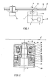
- Figure 1 shows a simplified block diagram of an optical disc apparatus as a preferred embodiment of the present infention.
- symbol 1 denotes a laser beam source that emits laser beams 2.
- Symbol 3 denotes a mirror, and symbol 4 denotes an objective lens that causes the laser beams 2 to be focussed onto the recording media surface of a disc.
- Symbol 5 denotes an optical focus position control device that causes the optical focus position to be accurately followed onto the tracks of the recording media of a disc by driving an objective lens 4 either in the vertical (up/down) or horizontal (left/right) direction.
- Symbol 6 denotes an optical head that contains all the optical devices mentioned above.
- Symbol 7 denotes a recording/erasing coil that provides that surface of the disc recording media with magnetism while either recording or erasing any information.
- Symbol 8 denotes an optical disc incorporating a disc recording media 8', and symbol 9 denotes motor that drives said optical disc to rotate.
- the focus control to be performed by the optical focus position control device 5, i.e., a fine adjustment of the incident laser beam focus position against the disc displacement made in the direction of the incident laser beam axis can be achieved by causing the objective lens 4 to move in the direction of the thickness of said optical disc 8.
- the tracking control to be performed by said optical focus position control device 5; i.e., a fine adjustment of the incidental laser beam focus position in dealing with the disc displacement in the radial direction can be performed by causing the objective lens 4 to move in the radial direction of the optical disc 8.
- FIGURE 2 shows a detailed construction of the optical focus position control system 5.
- An objective lens-mirror cylinder 10 supports the objective lens 4.
- the lens-mirror cylinder 10 is supported by a movable intermediate support member 11 via parallel springs 12 so that the lens-mirror cylinder 10 is movable in the radial (left/right), tracking direction with respect to the intermediate support member 11.
- a tracking permanent magnet 13, a tracking yoke plate 14 amd a tracking yoke 15 are secured to the intermediate support member 11, and form, in combination, a closed magnetic circuit.
- a tracking magnetic space 16 is provided between the tracking yoke plate 14 and the tracking yoke 15.
- a tracking drive coil 17 is secured to the lens-mirror cylinder 10 across the tracking magnetic space 16.
- magnetism will be generated in the tracking drive coil 17, and as a result, due to a combined effect with the other magnetism generated by the tracking permanent magnet 13, all the tracking drive coil 17, the lens-mirror cylinder 10, the objective lens 4, and a counter balance 18 are displaced in the radial direction.
- the counter balance 18 is secured to the bottom of the lens-mirror cylinder 10 so that the tracking drive force is applied to the center of the gravity of the tracking movable elements.
- a focussing permanent magnet 19, a focussing yoke plate 20, and a focussing yoke 21 form, in combination, a closed magnetic circuit. These elements are securely installed to a stationary holder 25 which fully supports the optical focus position control device.
- a focussing magnetic space 22 is formed between the focussing yoke plate 20 and the focussing yoke 21.
- a focus drive coil 23 is secured to the movable intermediate support member 11 across the focussing magnetic space 22.
- the mobable intermediate support member 11 is supported by the stationary holder 25 via parallel springs 24 so that the movable intermediate support member 11 is movable in the vertical direction, namely, in the direction of the incident laser beam axis with respect to the stationary holder 25.
- the tracking controller is driven by the electromagnetic effect that interacts between the tracking closed magnetic circuit secured to the intermediate support member 11 and the tracking drive coil 17 secured to the objective lens-mirror cylinder 10.
- the intermediate support member 11 and the objective lens-mirror cylinder 10 are connected to each other via the elestic material that is workable only to the left and to the right by moving in the radial direction, i.e., via a parallel spring 12 that moves in the direction of the disc radius.
- the objective lens-mirror cylinder 10 will have a resonance frequency fT which is represented by a formula when the objective lens-mirror cylinder 10 moves to the left and to the right.
- the movement phase delay caused by the displacement XT of the objective lens-mirror cylinder 10 in the tracking direction is 0° through 90° when 0 ⁇ f ⁇ fT, or 90° through 180° when fT ⁇ f, or near 180° when fT «f.
- the delay in the movement phase caused by the displacement XT of the objective lens-mirror cylinder 10 moving to the tracking target position YT should remain below 180° throughout the frequency bands of the tracking control signal.
- a phase advancing compensation circuit is used to advance the phase of the tracking drive signal FT, the phase delay is properly maintained below 180°. This ensures a stable tracking control.
- the focussing controller is driven by the electromagnetic effect that interacts between the focussing closed magnetic circuit secured to the stationary holder 25 and the focussing drive coil 23 secured to the intermediate support member 11.
- the intermediate support member 11 and the stationary holder 25 are connected to each other via the parallel spring 24 which is workable only in the vertical direction by moving in the direction of focussing.
- the weight of the movable part in the direction of focussing including the tracking control device is MF
- the spring constant of the parallel spring 24 moving in the direction of focussing is KF
- the objective lens-mirror cylinder 10 will be provided with a resonance frequency which is represented by a formula (hereinafter called the primary resonance frequency ) when performing vertrical (up/down) movements.
- the interim holder 11 and the objective lens-mirror cylinder 10 are connected to each other via the parallel spring 12 moving in the tracking direction.
- the aprallel spring 12 slightly moves in the vertical direction due to its elasticity.
- the objective lens-mirror cylinder 10 will have a resonance frequency ( hereinafter called the secondary resonance frequency ) represented as
- the movement phase delay in the displacement XF caused by the objective lens-mirror 10 in the focussing direction can be represented to be 0° through 90° when 0 ⁇ f ⁇ fF, where f (Hz) represents a frequency, whereas such a delay in the movement phase can be represent to be 90° through 270° when fF ⁇ f ⁇ f'F, and it will be 270° through 360° when f'F ⁇ f.
- the delay in the movement phase caused by the displacement XF of the objective lens-mirror cylinder 10 moving to the focussing target position YF should remain below 180° throughout the frequency bands of the focussing control signal.
- the phase advancing compensation circuit is used to advance the phase of the focussing drive signal FF, since there is a certain limit for advancing the phase amount, the phase cannot be compensated for in order that it can exceed 180° significantly.
- the second resonance frequency fF should be set at an optimum level higher than the frequency band of the focussing control signal.
- frequency bands available for the focussing control signal are variable N according to uses, generally, an optical disc apparatus uses 1 through 4KHz of the frequency bands. As a result, it was made clear that the secondary resonance frequency f'F should be set at a level above 7KHz.
- the secondary resonance frequency f'F can be determined by the spring constant KT' of the tracking parallel spring 12 when it moves in the focussing direction and by the weight MT of the moving parts in the tracking direction.
- the secondary resonance frequency f'F becomes large as the spring constant KT' becomes large and as the weight MT becomes small.
- the weight MT of the parts moving in the tracking direction cannot be decreased significantly. (Normally, the weight MT is designed in a range from 0.5 to 10 grams.)
- the inventors followed up trials for increasing the spring constant KT' of the tracking parallel spring 12 during its movement in the vertical direction.
- the spring constant KT' in the vertical direction (up/down) can be increased,by expanding the length XT and decreasing the thickness YT of the parallel spring 12.
- the secondary resonance frequency f'F can be obtained by an equation
- the tracking parallel spring 12 should be designed so that it can be provided with 20 through 50 micron meter of the thickness YT and an actual length taht is 100 up to 500 times the thickness YT.
- the delay in the movement phase caused by the displacement XF of the objective lens 4 against the focussing target position can be decreased below 180° within the frequency bands available for the focussing control signal. It is important that the phase advancing compensation circuit be used for correctly compensating for the movement phase.
- the resonance frequencies fF and fT there are N two kinds of the resonance frequencies fF and fT when the tracking control device and the focus control device are operated. If the damping characteristics in the directions of focussing and tracking control remain negligible, the resonance multiple factor in the resonance frequencies fF and fT will grow, thus causing any interference vibration to easily occur during either the focussing or tracking control operation. Also, when a certain frequency above the resonance frequency level is fed, the phase in responding to the displacement of the movable parts will be extremely delayed to a point very close to 180°, which will result in an extremely unstable optical focus position control operation. To prevent this and ensure satisfactory amount of the damping characteristics, the present invention effectively provides the following means.
- the primary improvement includes a latexed damping member painted on the focussing parallel spring and/or the tracking parallel spring.
- the plate rubber attached to the metal spring by an adhesive is not suited for the device, because the spring constant becomes high due to the adhesive.
- viscose-elastic materials such as silicon rubber, butyl rubber, silicon-butyl rubber, and acrylic-ethylene rubber, foaming synthetic resin such as foamed polyurethane, and viscose fluid such as silicon grease, can be made available.
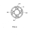
- FIGURE 3 shows a plane view of the focussing parallel spring 24.
- the focussing parallel spring 24 has a structure that connects two concentric circles, where two flat sheet springs, each being connected to four arms at the edges, are provided in the upper and lower positions.
- the parallel spring 24 moving in the direction of focus causes the intermediate holder 11 to move only in the vertical direction with respect to the stationary holder 25.(see FIGURE 2.)
- Damping material 26 is bonded to the portion C of the surface of the focussing parallel spring 24, where the largest amount of the relative displacement exists, thus resulting in greater damping characteristics in the direction of focus.
- viscose-elastic materials such as silicon-rubber, butyl rubber, silicon-butyl rubber, and acrylic-ethylene rubber, and foaming synthetic resin such as foamed polyurethane, can be made available.
- the third improvement is to form the focussing parallel spring and/or the tracking parallel spring with a vibration-proof alloy such as manganese-copper alloy, ferro-aluminum alloy, nickel-titanium alloy, and magnesium alloy.
- a vibration-proof alloy such as manganese-copper alloy, ferro-aluminum alloy, nickel-titanium alloy, and magnesium alloy.
- the present invention provides a variety of means for effectively preventing the optical focus position control device from causing its leakage mangetism to adversely affect the recording media 8' of the optical disc 8. Such effective means are described below.
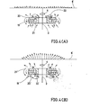
- FIGURE 4(A) shows a sectional view of a focus controller incorporating an improved means as a preferred embodiemnt of the present invention
- FIGURE 3(B) shows a sectional view of the other focus controller without incorporating any improved means.
- Symbols N and S respectively denote the north and south poles.
- the focus controller incorporating an improved means related to the present invention provides magnetic space 22 available s for the focussing operation in an area close to the optical disc. This construction minimizes leakage magnetism that otherwise adversely affects the recording media 8' of the optical disc.
- leakage magnetism will significantly affect the surface of the recording media 8' of the optical disc if the magnetic space 22' for the focussing operation is provided in an area remote from the optical disc as shown in FIGURE 3(B).
- Length of each arrow in FIGURES 3(A) and 3(B) denotes the intensity of the leakage magnetism at the respective position, while the direction of the leakage magnetism is shown in the arrowed direction.
- FIGURE 5(A) shows a sectional view of the tracking controller incorporating an improved means as a preferred embodiment of- the present invention
- FIGURES 5(B) and 5(C) show sectional views of the other tracking controller without incorporating any improved means.
- the tracking controller incorporating an improved means related to the present invention provides the permanent magnet 13 available for the tracking operation in the center position of the closed magnetic circuit. This construction minimizes leakage magnetism that otherwise adversely affects the recording media 8' of the optical disc.
- the leakage magnetism becomes large as the gap of the tracking magnetic space becomes large.
- the gap of the tracking magnetic space is made as narrow as possible.
- the objective lens must be movable in two dimensions, namely, up/down and left/right. If both of the tracking control magnetic circuit and the focus control magnetic circuit are supported by the stationary holder, the tracking coil must be movable in the two dimensions within the tracking magnetic space. This requires a wide magnetic space.
- the tracking magnetic circuit is supported by the movable intermediate holder 11.
- the tracking drive coil 17 is required to move only in the left/right direction within the tracking magnetic space 16. This will effectively minimize the gap of the tracking magnetic space 16, and the leakage magnetism.
- the focusing and/or tracking means can be applied to any head positioning device for a recording disc, the head being used for recording, playing back or erasing information or for performing any combination of these functions.
Landscapes
- Optical Recording Or Reproduction (AREA)
Applications Claiming Priority (4)
| Application Number | Priority Date | Filing Date | Title |
|---|---|---|---|
| JP68771/83 | 1983-04-18 | ||
| JP6877183A JPS59193552A (ja) | 1983-04-18 | 1983-04-18 | 光集束位置制御装置 |
| JP59053842A JPH0756696B2 (ja) | 1984-03-19 | 1984-03-19 | 光集束位置制御装置 |
| JP53842/84 | 1984-03-19 |
Publications (3)
| Publication Number | Publication Date |
|---|---|
| EP0122816A2 true EP0122816A2 (de) | 1984-10-24 |
| EP0122816A3 EP0122816A3 (en) | 1985-11-27 |
| EP0122816B1 EP0122816B1 (de) | 1990-07-18 |
Family
ID=26394564
Family Applications (1)
| Application Number | Title | Priority Date | Filing Date |
|---|---|---|---|
| EP84302661A Expired EP0122816B1 (de) | 1983-04-18 | 1984-04-18 | Einstellung der optischen Fokussierung bei einem optischen Speicherverfahren |
Country Status (3)
| Country | Link |
|---|---|
| US (1) | US4658390A (de) |
| EP (1) | EP0122816B1 (de) |
| DE (1) | DE3482725D1 (de) |
Cited By (2)
| Publication number | Priority date | Publication date | Assignee | Title |
|---|---|---|---|---|
| GB2233107A (en) * | 1989-06-07 | 1991-01-02 | Unisys Corp | "lens shuttle mechanism for microfilmer camera". |
| EP0604159A3 (de) * | 1992-12-21 | 1994-12-14 | Canon Kk | Magneto-optisches Aufzeichnungsgerät. |
Families Citing this family (16)
| Publication number | Priority date | Publication date | Assignee | Title |
|---|---|---|---|---|
| US4745589A (en) * | 1984-10-04 | 1988-05-17 | Seiko Epson Kabushiki Kaisha | Objective lens actuator having movements restricting control means for an optical head |
| DE3683227D1 (de) * | 1985-08-14 | 1992-02-13 | Philips Patentverwaltung | Optische abtasteinheit. |
| KR900006183B1 (ko) * | 1986-03-04 | 1990-08-25 | 상요 덴기 가부시기가이샤 | 광학식 픽업 장치 |
| US4845699A (en) * | 1986-03-04 | 1989-07-04 | Sanyo Electric Co., Ltd. | Electric mechanical transducer and optical type pickup apparatus driven by a magnetic field |
| US4782476A (en) * | 1986-06-24 | 1988-11-01 | Sharp Kabushiki Kaisha | Objective lens-driving unit |
| JPH01177416U (de) * | 1988-06-07 | 1989-12-19 | ||
| JPH02187932A (ja) * | 1989-01-12 | 1990-07-24 | Olympus Optical Co Ltd | 光ビーム移動装置 |
| US5138497A (en) * | 1991-03-15 | 1992-08-11 | Eastman Kodak Company | High speed focusing lens assembly |
| US5563871A (en) * | 1993-11-09 | 1996-10-08 | International Business Machines Corporation. | Rotary actuator with a magnetic bias bearing configuration for rotating an optical element in an optical data storage system |
| KR100329918B1 (ko) * | 1998-10-28 | 2002-09-04 | 삼성전자 주식회사 | 픽업엑추에이터 |
| US6829708B1 (en) * | 1999-03-27 | 2004-12-07 | Microsoft Corporation | Specifying security for an element by assigning a scaled value representative of the relative security thereof |
| AU2003302166A1 (en) * | 2003-01-02 | 2004-07-29 | Covi Technologies, Inc. | Optical block assembly |
| US7113351B2 (en) * | 2003-01-02 | 2006-09-26 | Covi Technologies, Inc. | Systems and methods for actuating lens assemblies |
| TWI298805B (en) * | 2005-02-15 | 2008-07-11 | Sony Corp | Lens unit and imaging apparatus |
| CN100516958C (zh) * | 2005-06-10 | 2009-07-22 | 力相光学股份有限公司 | 自动对焦镜头的悬吊支撑装置的制造方法 |
| JP4589909B2 (ja) * | 2006-10-27 | 2010-12-01 | 株式会社日立メディアエレクトロニクス | 対物レンズ駆動装置 |
Family Cites Families (15)
| Publication number | Priority date | Publication date | Assignee | Title |
|---|---|---|---|---|
| US4100576A (en) * | 1976-04-28 | 1978-07-11 | Zenith Radio Corporation | Electromagnetic optical beam controller having an eddy current damper for arresting mechanical resonance |
| US4302830A (en) * | 1978-05-10 | 1981-11-24 | Olympus Optical Company Ltd. | Optical information reading-out apparatus |
| FR2425782B1 (fr) * | 1978-05-10 | 1988-02-12 | Olympus Optical Co | Appareil de lecture d'informations optiques |
| NL7920100A (nl) * | 1978-11-01 | 1981-02-27 | Hitachi Ltd | Inrichting voor het detecteren van magneto-optische anisotropie. |
| GB2052829B (en) * | 1979-04-27 | 1983-01-12 | Olympus Optical Co | Apparatus for driving objective lens in tracking direction |
| GB2060927B (en) * | 1979-07-24 | 1984-02-01 | Universal Pioneer Corp | Signal reading device for optical discs |
| US4437177A (en) * | 1979-11-12 | 1984-03-13 | Nippon Telegraph & Telephone Public Corporation | Small-sized video or audio pickup device having a beam deflector disposed within a focusing device support |
| JPS5720927A (en) * | 1980-07-09 | 1982-02-03 | Olympus Optical Co Ltd | Objective lens driver |
| GB2088646B (en) * | 1980-10-24 | 1984-09-12 | Sony Corp | Pick-up assemblies for disc players |
| JPS57103131A (en) * | 1980-12-18 | 1982-06-26 | Sony Corp | Biaxial driver |
| US4482986A (en) * | 1981-01-30 | 1984-11-13 | Sony Corporation | Objective lens mount for optical disc player |
| JPS57147148A (en) * | 1981-03-05 | 1982-09-10 | Olympus Optical Co Ltd | Information reproducer with magnetooptic system |
| JPS57181436A (en) * | 1981-05-01 | 1982-11-08 | Toshiba Corp | Optical disc device |
| JPS5812145A (ja) * | 1981-07-13 | 1983-01-24 | Matsushita Electric Ind Co Ltd | 対物レンズ駆動装置 |
| CA1208361A (en) * | 1983-01-25 | 1986-07-22 | Yoshikazu Fujii | Optical focus position control in optical disc apparatus |
-
1984
- 1984-04-16 US US06/600,374 patent/US4658390A/en not_active Expired - Lifetime
- 1984-04-18 DE DE8484302661T patent/DE3482725D1/de not_active Expired - Lifetime
- 1984-04-18 EP EP84302661A patent/EP0122816B1/de not_active Expired
Cited By (5)
| Publication number | Priority date | Publication date | Assignee | Title |
|---|---|---|---|---|
| GB2233107A (en) * | 1989-06-07 | 1991-01-02 | Unisys Corp | "lens shuttle mechanism for microfilmer camera". |
| US5014085A (en) * | 1989-06-07 | 1991-05-07 | Unisys Corporation | Lens shuttle mechanism for microfilm camera |
| GB2233107B (en) * | 1989-06-07 | 1993-09-01 | Unisys Corp | Lens shuttle mechanism for microfilmer camera |
| EP0604159A3 (de) * | 1992-12-21 | 1994-12-14 | Canon Kk | Magneto-optisches Aufzeichnungsgerät. |
| US5563853A (en) * | 1992-12-21 | 1996-10-08 | Canon Kabushiki Kaisha | Magneto-optical recording apparatus that compensates for magnetic fields leaking from an objective lens actuator and a linear motor |
Also Published As
| Publication number | Publication date |
|---|---|
| US4658390A (en) | 1987-04-14 |
| EP0122816B1 (de) | 1990-07-18 |
| DE3482725D1 (de) | 1990-08-23 |
| EP0122816A3 (en) | 1985-11-27 |
Similar Documents
| Publication | Publication Date | Title |
|---|---|---|
| US4660190A (en) | Optical focus position control in optical disc apparatus | |
| US4658390A (en) | Optical focus position control in an optical memory system | |
| JP3154141B2 (ja) | 緩衝装置及び緩衝装置を用いた円盤状記録媒体用の記録及び/又は再生装置 | |
| KR100378134B1 (ko) | 대물렌즈구동장치 | |
| JPS6339980B2 (de) | ||
| EP0115666A2 (de) | Einstellung der optischen Fokussierung bei einem Gerät mit optischer Scheibe | |
| KR100362215B1 (ko) | (요크브릿지를이용하지않는)렌즈이동장치 | |
| KR100695460B1 (ko) | 병렬 제어 액추에이터를 구비한 광학 주사장치 및 광학 재생장치 | |
| CA1219073A (en) | Optical focus position control in an optical memory system | |
| EP0314200B1 (de) | Einstellungsvorrichtung der optischen Fokussierung | |
| EP0318772B1 (de) | Einstellungsvorrichtung der optischen Fokussierung | |
| JPH10255290A (ja) | 光学ピックアップ用対物レンズ | |
| JPH09161281A (ja) | 光ピックアップ装置 | |
| JPH0756696B2 (ja) | 光集束位置制御装置 | |
| JPS6243256B2 (de) | ||
| JP2706357B2 (ja) | 光学式情報記録再生装置 | |
| JPH03154235A (ja) | アクチュエータ | |
| JPS6284437A (ja) | 対物レンズ駆動装置 | |
| JP2621200B2 (ja) | 対物レンズアクチュエータ | |
| JP2602004B2 (ja) | 対物レンズ駆動装置 | |
| JP2720557B2 (ja) | 対物レンズ駆動装置 | |
| JPS59195336A (ja) | 光集束位置制御装置 | |
| JPH0438725A (ja) | 光ヘッド | |
| JPS6284438A (ja) | 対物レンズ駆動装置 | |
| JP2000155962A (ja) | 光学的情報記録再生装置 |
Legal Events
| Date | Code | Title | Description |
|---|---|---|---|
| PUAI | Public reference made under article 153(3) epc to a published international application that has entered the european phase |
Free format text: ORIGINAL CODE: 0009012 |
|
| AK | Designated contracting states |
Designated state(s): DE FR GB IT |
|
| PUAL | Search report despatched |
Free format text: ORIGINAL CODE: 0009013 |
|
| AK | Designated contracting states |
Designated state(s): DE FR GB IT |
|
| 17P | Request for examination filed |
Effective date: 19860505 |
|
| 17Q | First examination report despatched |
Effective date: 19871109 |
|
| ITF | It: translation for a ep patent filed | ||
| GRAA | (expected) grant |
Free format text: ORIGINAL CODE: 0009210 |
|
| AK | Designated contracting states |
Kind code of ref document: B1 Designated state(s): DE FR GB IT |
|
| REF | Corresponds to: |
Ref document number: 3482725 Country of ref document: DE Date of ref document: 19900823 |
|
| ET | Fr: translation filed | ||
| ITTA | It: last paid annual fee | ||
| PLBE | No opposition filed within time limit |
Free format text: ORIGINAL CODE: 0009261 |
|
| STAA | Information on the status of an ep patent application or granted ep patent |
Free format text: STATUS: NO OPPOSITION FILED WITHIN TIME LIMIT |
|
| 26N | No opposition filed | ||
| REG | Reference to a national code |
Ref country code: GB Ref legal event code: IF02 |
|
| PGFP | Annual fee paid to national office [announced via postgrant information from national office to epo] |
Ref country code: FR Payment date: 20030408 Year of fee payment: 20 |
|
| PGFP | Annual fee paid to national office [announced via postgrant information from national office to epo] |
Ref country code: GB Payment date: 20030416 Year of fee payment: 20 |
|
| PGFP | Annual fee paid to national office [announced via postgrant information from national office to epo] |
Ref country code: DE Payment date: 20030502 Year of fee payment: 20 |
|
| PG25 | Lapsed in a contracting state [announced via postgrant information from national office to epo] |
Ref country code: GB Free format text: LAPSE BECAUSE OF EXPIRATION OF PROTECTION Effective date: 20040417 |
|
| REG | Reference to a national code |
Ref country code: GB Ref legal event code: PE20 |