EP0122830A2 - Filtre optique directionnel - Google Patents
Filtre optique directionnel Download PDFInfo
- Publication number
- EP0122830A2 EP0122830A2 EP84400518A EP84400518A EP0122830A2 EP 0122830 A2 EP0122830 A2 EP 0122830A2 EP 84400518 A EP84400518 A EP 84400518A EP 84400518 A EP84400518 A EP 84400518A EP 0122830 A2 EP0122830 A2 EP 0122830A2
- Authority
- EP
- European Patent Office
- Prior art keywords
- grooves
- media
- radiant energy
- light
- filter
- Prior art date
- Legal status (The legal status is an assumption and is not a legal conclusion. Google has not performed a legal analysis and makes no representation as to the accuracy of the status listed.)
- Ceased
Links
Images
Classifications
-
- G—PHYSICS
- G02—OPTICS
- G02B—OPTICAL ELEMENTS, SYSTEMS OR APPARATUS
- G02B5/00—Optical elements other than lenses
- G02B5/20—Filters
- G02B5/22—Absorbing filters
-
- G—PHYSICS
- G02—OPTICS
- G02B—OPTICAL ELEMENTS, SYSTEMS OR APPARATUS
- G02B5/00—Optical elements other than lenses
Definitions
- This invention relates to radiant energy filtration and more specifically to a directional filter which attenuates radiant energy such as light entering the filter from outside of a pre-determined angle of incidence.
- the invention is useful for heads down displays in aircraft cockpits, although it may also find utility in a number of other applications using video displays under adverse lighting conditions.
- Heads down displays of the type described are used to display a wide variety of aircraft navigational information in the cockpit of the craft. Often, different information is superimposed or is presented in detail which is difficult to read under varying ambient light conditions. When ambient light is low, as in night flying, it is a relatively simple task to reduce the brightness of the aircraft display. On the other hand, there are frequently ambient light conditions which require a display brightness that would be impractical either as a result of the capabilities of the display or the safety or comfort of the viewer. For example, if sunlight is creating a high glare condition, the display would not only have to overcome the glare but be bright enough for the information provided by the display to be discernible over background lighting conditions. Additionally, during the aircraft's maneuvering, lighting conditions can be expected to change rapidly. While an optical sensor can be used to sense ambient light intensity conditions, glare conditions can not always be determined by merely measuring ambient light levels.
- the fixed position of the pilot-viewer enables the use of filter techniques which direct light in a single direction. For this reason, directional filters of various types have been placed in front of the CRT displays in order to block light from external sources which would tend to cause glare, while passing that light from the CRT which is traveling in the direction of the viewer. While there is a certain amount of optical amplitude (brightness) loss inherent in the use of any filter, the loss of brightness is compensated for by the decrease in glare conditions.
- Prior art light filtration techniques include the use of neutral density filters. Such filters attenuate external source light as well as light from the display; however, external source light necessarily passes the filter twice and, therefore, is blocked by a square of the attenuation of light from the display itself.
- a notch filter is sometimes used to select the specific colors of light which are generated by or used in connection with the display. Ambient light would be highly filtered because only a small percentage of the ambient light would fall within the range of the notch filter. With the use of color display techniques, the use of a notch filter is less practical since several different wave lengths must be within the admittance bands of the notch filter.
- Directional filters are used to transmit light only in a desired direction. If it is anticipated that ambient light which would cause glare would emanate from a direction other than that of the anticipated direction of the viewer from the display, it is possible to filter such ambient light using directional filters.
- a sheet of material is etched in order to form a large number of holes. The surfaces of the material at the holes have a high absorbency in order to eliminate reflection along the holes and at the surface of the sheet. Frequently, the sheets are stacked in order to enhance the attenuation effect of the filter. This technique is frequently expensive and may have light attenuation characteristics which are excessive.
- Another directional filtration technique involves the construction of a filter plate from a plurality of sheets of thin material.
- the thin sheets are stacked so that each sheet is parallel to an admittance direction of light.
- the filter plate is taken from the stack of sheets by cutting a slice across the stack. This results in the filter plate being generally orthogonal to the direction of the individual thin sheets from which it is made, with the slice direction varying from the orthogonal direction for central viewing angles which vary from normal to the surface of the filter.
- This technique is subject to slight optical distortion and such a filter is expensive to produce.
- an object of the present invention to provide a light filter which has high attenuation ratio for unwanted-verses-wanted light. It is desired that such a filter have minimal attenuation of light in a desired viewing direction and have a maximum attenuation of light passing from beyond a given angle. It is further desired that the filter be useable with full color displays, as well as for the viewing of external conditions, as in the case of heads-up displays. It is further desired that the filter maintain a high effectiveness in adverse ambient lighting conditions with a minimum of attenuation of displayed lighting under those adverse conditions.
- the desired filter would be useful for direct view displays having passive and active illumination characteristics, as well as heads-up displays (HUD'S) and wind screens used for external viewing by humans and electronic sensors.
- a radiant energy filter is formed from a transparent plate having a plurality of etched grooves thereon.
- the grooves have a high energy absorbency characteristic, particularly for energy radiating toward the grooves from within the plate. Therefore, radiant energy entering the plate from an angle which would cause the radiant energy to impinge upon the grooves is highly attenuated, whereas radiant energy entering the plate and not impinging upon the grooves is attenuated only by the optical characteristics of the plate.
- Advantages include a high attenuation-to-attenuation ratio for light entering from beyond a view range, as compared with light entering from within a view range. Further advantages include a high filtration efficiency in a wide variety of applications.
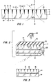
- the directional optical filter consists of a substantially transparent plate 13 having a plurality of grooves 15 cut into one side 16 of the plate 13.
- the grooves 15 extend in a parallel fashion across the face of the plate 13, as can be seen in Figure 2. It is alternatively possible to arrange the grooves 15 in different patterns, such as concentric circles (not shown).
- the grooves 15 have a high light absorbency characteristic for light entering the grooves 15 from within the plate 13.
- the absorbency of light passing from within the plate 13 to the grooves 15 is 0.9 or greater, where 1.0 is perfect absorbency.
- the grooves 15 may be filled with light absorbing material 18 so that light impinging upon the grooves 15 from outside of the plate 13 is also absorbed at the grooves 15.
- the grooves 15 are created by etching the plate 13 through a mask.
- the grooves 15 are formed by using a special mold for the filter plate 13. The mold (not shown) would have appropriate knife edges along a surface corresponding to side 16 of the plate 13.
- the plate 13 is made of a media which is able to transmit the radiant energy to be filtered, in this case light.
- Typical materials include glass, epoxy and methyl methacrylate.
- the media itself may have radiant energy filtering properties.
- the media may include a polarized light filter, a neutral density partial absorption characteristic or a selective filtration characteristic.
- any light passing through the plate 13 will either hit or miss one of the grooves 15 according to the direction that the 1ight is travelling with respect to the plate 13 and the proximity of the light's path to the grooves 15. That light impinging upon the grooves 15 is for the most part absorbed and that light not impinging upon the grooves 15 is for the most part transmitted. Beyond a certain angle 0, substantially all light is absorbed. Taking into account the refraction characteristics of the plate 13 itself, this angle 0 translates to an exterior angle of 0.
- This absorbency rate is maintained more or less constant for angles from the normal direction which do not exceed the angular cut from normal of the grooves 15.
- the absorbency of the filter 11 is reduced in a linear fashion between that angular direction and 0 (or ⁇ ', according to one's point of reference).
- the effects of the filter 11 are such that the viewer can be looking from either side A or B.
- the viewer will probably be observering from side A because an anti-reflection coating (not shown) will be used in such a way that the anti-reflection coating will cover the light absorbing material 18 in the grooves 15.
- Anti-glare coatings are well known, with the anti-glare coatings of the present invention being defined by military specification MIL-C-14806A.
- the optical filter 11 is shown placed over a passive display such as a liquid nematic crystal display 21.
- a separate light dispersing element 23 is disposed between the display 21 and the filter 11 in Order to provide illumination for the display 21 when needed. This may be necessary where the direction of illuminating light exceeds the angle 0 ( Figure 1).
- the illuminating light would, of course, come from a preferred direction and have preferred spectral characteristics, thereby reducing induced glare in a manner known to those skilled in the art.
- external light source 25 with the filter, provided that the absorbency characteristics of the filter 11 are taken into consideration. In practice, it is unlikely that the optical filter would be used with a purely passive display, but it is anticipated that some displays will use a combination of passive and active display elements, thereby necessitating the use of anti-glare filteration.
- the filter 11 is shown as placed against a conventional face plate 31 for a cathode ray tube (CRT). As is the case with the above configurations, it is possible to invert the filter 11 so that the grooves 15 face the displayed image, that is, the image transmitted through a face plate 31.
- CRT cathode ray tube
- the grooves 15 can be laid out as concentric circles (not shown), thereby effectively reducing glare from a variety of directions. It is also possible to form the grooves 15 at an angle other than normal to the side 16 from which they extend (configuration not shown). This creates a central viewing direction which is at an angle other than normal to the plate 13.
- the present invention is also adaptable to shorter wave length energy such as ultraviolet light and to longer wave length energy such as infrared and microwave energy.
Landscapes
- Physics & Mathematics (AREA)
- General Physics & Mathematics (AREA)
- Optics & Photonics (AREA)
- Optical Elements Other Than Lenses (AREA)
- Devices For Indicating Variable Information By Combining Individual Elements (AREA)
Applications Claiming Priority (2)
| Application Number | Priority Date | Filing Date | Title |
|---|---|---|---|
| US06/476,297 US4621898A (en) | 1983-03-17 | 1983-03-17 | Directional optical filter |
| US476297 | 1990-02-07 |
Publications (2)
| Publication Number | Publication Date |
|---|---|
| EP0122830A2 true EP0122830A2 (fr) | 1984-10-24 |
| EP0122830A3 EP0122830A3 (fr) | 1987-06-10 |
Family
ID=23891286
Family Applications (1)
| Application Number | Title | Priority Date | Filing Date |
|---|---|---|---|
| EP84400518A Ceased EP0122830A3 (fr) | 1983-03-17 | 1984-03-14 | Filtre optique directionnel |
Country Status (3)
| Country | Link |
|---|---|
| US (1) | US4621898A (fr) |
| EP (1) | EP0122830A3 (fr) |
| JP (1) | JPS59177501A (fr) |
Cited By (3)
| Publication number | Priority date | Publication date | Assignee | Title |
|---|---|---|---|---|
| EP0354672A3 (fr) * | 1988-08-08 | 1990-10-10 | Minnesota Mining And Manufacturing Company | Film collimateur de lumière |
| EP0658780A1 (fr) * | 1993-12-01 | 1995-06-21 | Raimondi, Enrico | Filtre directionnel pour appareil d'éclairage et procédé de fabrication |
| US8416355B2 (en) | 2007-06-20 | 2013-04-09 | Tc View Ltd. | Directional filter device for controlling direction of maximal blocking of incident light |
Families Citing this family (99)
| Publication number | Priority date | Publication date | Assignee | Title |
|---|---|---|---|---|
| JPH0430561Y2 (fr) * | 1985-06-21 | 1992-07-23 | ||
| US5204160A (en) * | 1988-08-08 | 1993-04-20 | Minnesota Mining And Manufacturing Company | Light-collimating film |
| US4973139A (en) * | 1989-04-07 | 1990-11-27 | Hughes Aircraft Company | Automotive head-up display |
| US4997263A (en) * | 1989-06-12 | 1991-03-05 | Allied-Signal Inc. | Ambient light illuminated liquid crystal display system |
| US5382985A (en) * | 1991-06-14 | 1995-01-17 | The United States Of America As Represented By The Secretary Of The Air Force | Thermorefractive optical switch |
| US5243464A (en) * | 1992-07-20 | 1993-09-07 | Martin Marietta Energy Systems, Inc. | Damage tolerant light absorbing material |
| FR2738355B1 (fr) * | 1995-08-28 | 1997-10-31 | Aerospatiale | Piege a lumiere |
| US5877829A (en) * | 1995-11-14 | 1999-03-02 | Sharp Kabushiki Kaisha | Liquid crystal display apparatus having adjustable viewing angle characteristics |
| JP3764205B2 (ja) * | 1996-04-10 | 2006-04-05 | 株式会社きもと | 視界制御シートの製造方法 |
| US6473220B1 (en) | 1998-01-22 | 2002-10-29 | Trivium Technologies, Inc. | Film having transmissive and reflective properties |
| US6612840B1 (en) * | 2000-04-28 | 2003-09-02 | L-3 Communications Corporation | Head-up display simulator system |
| KR100779777B1 (ko) * | 2000-11-02 | 2007-11-27 | 쓰리엠 이노베이티브 프로퍼티즈 컴파니 | 직시형 방사 디스플레이의 휘도 및 대비 증대 |
| US6398370B1 (en) | 2000-11-15 | 2002-06-04 | 3M Innovative Properties Company | Light control device |
| GB0131088D0 (en) * | 2001-12-29 | 2002-02-13 | Meritor Automotive Gmbh | Sun blind assembly |
| US7345824B2 (en) | 2002-03-26 | 2008-03-18 | Trivium Technologies, Inc. | Light collimating device |
| US7595934B2 (en) | 2002-03-26 | 2009-09-29 | Brilliant Film Llc | Integrated sub-assembly having a light collimating or transflecting device |
| US6905219B2 (en) * | 2002-05-09 | 2005-06-14 | 3M Innovative Properties Company | Display device |
| US20030231151A1 (en) * | 2002-06-17 | 2003-12-18 | Barlow James E. | Apparatus and method for light enhancing |
| TW200506446A (en) * | 2003-05-20 | 2005-02-16 | Trivium Technologies Inc | Devices for use in non-emissive displays |
| JP2005338270A (ja) * | 2004-05-25 | 2005-12-08 | Dainippon Printing Co Ltd | 視野角制御シート |
| JP2006171701A (ja) * | 2004-11-18 | 2006-06-29 | Dainippon Printing Co Ltd | 視野角制御シート及びこれを用いた液晶表示装置 |
| JP2006171700A (ja) * | 2004-11-18 | 2006-06-29 | Dainippon Printing Co Ltd | 視野角制御シート及びこれを用いた液晶表示装置 |
| US7616332B2 (en) | 2004-12-02 | 2009-11-10 | 3M Innovative Properties Company | System for reading and authenticating a composite image in a sheeting |
| DE102005041242A1 (de) * | 2005-08-31 | 2007-03-01 | Merck Patent Gmbh | Verfahren zur Strukturierung von Oberflächen von Substraten |
| CN101370857B (zh) * | 2006-01-12 | 2012-09-05 | 3M创新有限公司 | 光准直薄膜 |
| WO2007148651A1 (fr) * | 2006-06-20 | 2007-12-27 | Nec Corporation | Appareil d'Éclairage, procÉdÉ d'Éclairage et appareil d'affichage |
| JP4816395B2 (ja) * | 2006-10-12 | 2011-11-16 | 株式会社日立製作所 | 映像表示装置及びそれに用いられる光拡散部材 |
| US7800825B2 (en) | 2006-12-04 | 2010-09-21 | 3M Innovative Properties Company | User interface including composite images that float |
| DE602007010407D1 (de) * | 2006-12-05 | 2010-12-23 | Lg Electronics Inc | Film für Anzeigevorrichtung, Filter mit Film und Anzeigevorrichtung mit Filter |
| WO2009009258A2 (fr) | 2007-07-11 | 2009-01-15 | 3M Innovative Properties Company | Feuille présentant une image composite flottante |
| EP2208096B1 (fr) | 2007-10-16 | 2019-11-27 | 3M Innovative Properties Company | Film anti-reflet à transmission plus élevée |
| WO2009070434A1 (fr) | 2007-11-27 | 2009-06-04 | 3M Innovative Properties Company | Procédés de formation de feuille avec une image composite qui flotte et un outillage maître |
| KR101546554B1 (ko) * | 2007-12-21 | 2015-08-25 | 쓰리엠 이노베이티브 프로퍼티즈 컴파니 | 광 제어 필름 |
| US8908151B2 (en) * | 2008-02-14 | 2014-12-09 | Nikon Corporation | Illumination optical system, exposure apparatus, device manufacturing method, compensation filter, and exposure optical system |
| US20090213593A1 (en) * | 2008-02-26 | 2009-08-27 | Reflexite Corporation | Optical device and system for black level enhancement and methods of use thereof |
| TW200946775A (en) | 2008-02-27 | 2009-11-16 | Brilliant Film Llc | Concentrators for solar power generating systems |
| KR20090101084A (ko) * | 2008-03-21 | 2009-09-24 | 후지논 가부시키가이샤 | 촬상 필터 |
| US8210724B2 (en) * | 2008-03-24 | 2012-07-03 | I/O Controls Corporation | Low glare lighting for a transit vehicle |
| US8205995B2 (en) * | 2008-08-07 | 2012-06-26 | Reflexite Corporation | Optical device and system for privacy or contrast enhancement and methods of use thereof |
| US8057715B2 (en) * | 2008-08-28 | 2011-11-15 | Reflexite Corporation | Method for making an optical device and system for privacy or contrast enhancement |
| US8111463B2 (en) | 2008-10-23 | 2012-02-07 | 3M Innovative Properties Company | Methods of forming sheeting with composite images that float and sheeting with composite images that float |
| US7995278B2 (en) | 2008-10-23 | 2011-08-09 | 3M Innovative Properties Company | Methods of forming sheeting with composite images that float and sheeting with composite images that float |
| US20100264163A1 (en) | 2008-11-13 | 2010-10-21 | Tevs Nikolai R | Product Dispensing Apparatus And Method |
| CN202661719U (zh) | 2009-03-10 | 2013-01-09 | 3M创新有限公司 | 具有浮现的合成图像的用户接口 |
| EP2443492A4 (fr) | 2009-06-18 | 2018-01-10 | 3M Innovative Properties Company | Film anti-reflet |
| EP2550155B1 (fr) | 2010-03-25 | 2020-11-04 | 3M Innovative Properties Company | Couche composite |
| KR101831461B1 (ko) | 2010-03-25 | 2018-02-22 | 쓰리엠 이노베이티브 프로퍼티즈 컴파니 | 다중 스트라이프 압출물을 제조하기 위한 압출 다이 요소, 압출 다이 및 방법 |
| WO2012162458A2 (fr) * | 2011-05-25 | 2012-11-29 | 3M Innovative Properties Company | Film régulateur de lumière |
| CN109177254B (zh) | 2011-10-05 | 2021-05-14 | 3M创新有限公司 | 三维聚合物股线结网、模头和制备它们的方法 |
| USD689055S1 (en) | 2012-01-09 | 2013-09-03 | 3M Innovative Properties Company | Multi-panel case for a tablet electronic device |
| USD689054S1 (en) | 2012-01-09 | 2013-09-03 | 3M Innovative Properties Company | Foldable case for a tablet electronic device |
| JP2015516900A (ja) | 2012-03-26 | 2015-06-18 | スリーエム イノベイティブ プロパティズ カンパニー | 開口部の配列を含むフィルム及びその製造方法 |
| USD678294S1 (en) | 2012-04-13 | 2013-03-19 | 3M Innovative Properties Company | Case for a tablet electronic device |
| BR102013013559A2 (pt) * | 2013-05-31 | 2015-07-14 | Roberto Massaru Amemiya | Filmadora com captação tridimensional de raios e televisão produtora de imagem real formada à frente e atrás da superfície da televisão; dispositivos de filtro de raios paralelos; cristais líquidos emparelhados ou movimento de células ópticas ou filtro de raios paralelos com conjunto de lentes móveis incluindo lentes flexíveis multifocais; processos para obtenção desses dispositivos |
| US10185058B2 (en) | 2013-07-01 | 2019-01-22 | 3M Innovative Properties Company | Protection film suitable for illuminated display devices |
| WO2016003669A1 (fr) * | 2014-06-30 | 2016-01-07 | 3M Innovative Properties Company | Film anti-regard à 360 degrés |
| US20160124126A1 (en) | 2014-10-29 | 2016-05-05 | Sergiy Vasylyev | Angular selective light control sheeting and method of making the same |
| WO2017074951A1 (fr) | 2015-10-26 | 2017-05-04 | Reald Inc. | Système de confidentialité intelligent, appareil et procédé associés |
| CN114554177A (zh) | 2016-05-19 | 2022-05-27 | 瑞尔D斯帕克有限责任公司 | 广角成像定向背光源 |
| US10126575B1 (en) | 2017-05-08 | 2018-11-13 | Reald Spark, Llc | Optical stack for privacy display |
| US20210199879A1 (en) | 2017-05-08 | 2021-07-01 | Reald Spark, Llc | Optical stack for imaging directional backlights |
| JP7204073B2 (ja) | 2017-05-08 | 2023-01-16 | リアルディー スパーク エルエルシー | 指向性ディスプレイ用の光学積層体 |
| US11227964B2 (en) | 2017-08-25 | 2022-01-18 | California Institute Of Technology | Luminescent solar concentrators and related methods of manufacturing |
| TWI878209B (zh) | 2017-09-15 | 2025-04-01 | 美商瑞爾D斯帕克有限責任公司 | 顯示裝置及應用於顯示裝置的視角控制光學元件 |
| US10948648B2 (en) | 2017-09-29 | 2021-03-16 | Reald Spark, Llc | Backlights having stacked waveguide and optical components with different coefficients of friction |
| WO2019090252A1 (fr) | 2017-11-06 | 2019-05-09 | Reald Spark, Llc | Appareil d'affichage de confidentialité |
| CN109976082B (zh) * | 2017-12-14 | 2021-11-23 | 台湾扬昕股份有限公司 | 投影幕及吸光膜 |
| KR102759510B1 (ko) | 2018-01-25 | 2025-02-04 | 리얼디 스파크, 엘엘씨 | 프라이버시 디스플레이를 위한 터치스크린 |
| TWI827580B (zh) | 2018-01-25 | 2024-01-01 | 美商瑞爾D斯帕克有限責任公司 | 用於防窺顯示裝置之反射式光學堆疊物 |
| EP3769516B1 (fr) | 2018-03-22 | 2025-06-25 | RealD Spark, LLC | Guide d'onde optique pour rétro-éclairage directionnel |
| US11362229B2 (en) | 2018-04-04 | 2022-06-14 | California Institute Of Technology | Epitaxy-free nanowire cell process for the manufacture of photovoltaics |
| US10955715B2 (en) | 2018-06-29 | 2021-03-23 | Reald Spark, Llc | Optical stack for privacy display |
| US20210271095A1 (en) * | 2018-07-12 | 2021-09-02 | Lg Innotek Co., Ltd. | Optical path control member and display device comprising same |
| CN112602011A (zh) | 2018-07-18 | 2021-04-02 | 瑞尔D斯帕克有限责任公司 | 用于可切换定向显示器的光学堆叠 |
| WO2020041522A1 (fr) * | 2018-08-21 | 2020-02-27 | California Institute Of Technology | Fenêtres mettant efficacement en œuvre des conducteurs transparents et procédés de fabrication associés |
| WO2020072643A1 (fr) | 2018-10-03 | 2020-04-09 | Reald Spark, Llc | Appareil de commande d'affichage de confidentialité |
| WO2020097156A1 (fr) | 2018-11-07 | 2020-05-14 | Reald Spark, Llc | Appareil d'affichage directionnel |
| WO2020146091A1 (fr) | 2019-01-07 | 2020-07-16 | Reald Spark, Llc | Empilement optique d'affichage de confidentialité |
| EP3924776B1 (fr) | 2019-02-12 | 2024-07-10 | RealD Spark, LLC | Dispositif d'affichage avec diffuseur pour afficheur de confidentialité |
| WO2020205800A1 (fr) | 2019-03-29 | 2020-10-08 | California Institute Of Technology | Appareil et systèmes destinés à l'incorporation d'un catalyseur efficace transparent en vue d'une application photoélectrochimique |
| TWI912252B (zh) | 2019-07-02 | 2026-01-21 | 美商瑞爾D斯帕克有限責任公司 | 定向顯示設備 |
| WO2021026018A1 (fr) * | 2019-08-02 | 2021-02-11 | Reald Spark, Llc | Empilement optique d'affichage de confidentialité |
| EP4438945B1 (fr) | 2019-10-02 | 2025-09-03 | RealD Spark, LLC | Appareil d'affichage de confidentialité |
| WO2021097040A1 (fr) | 2019-11-13 | 2021-05-20 | Reald Spark, Llc | Dispositif d'affichage à réduction de luminance hors axe uniforme |
| WO2021118936A1 (fr) | 2019-12-10 | 2021-06-17 | Reald Spark, Llc | Contrôle du reflet d'un dispositif d'affichage |
| CN114902093B (zh) | 2019-12-18 | 2025-09-26 | 瑞尔D斯帕克有限责任公司 | 用于隐私显示的环境光的控制 |
| WO2021222606A1 (fr) | 2020-04-30 | 2021-11-04 | Reald Spark, Llc | Appareil d'affichage directionnel |
| US11442316B2 (en) | 2020-04-30 | 2022-09-13 | Reald Spark, Llc | Directional display apparatus |
| EP4143631A4 (fr) * | 2020-04-30 | 2024-05-29 | RealD Spark, LLC | Appareil d'affichage directionnel |
| US12402418B2 (en) | 2020-06-12 | 2025-08-26 | California Institute Of Technology | Systems and methods for non-epitaxial high Schottky-barrier heterojunction solar cells |
| WO2022026536A1 (fr) | 2020-07-29 | 2022-02-03 | Reald Spark, Llc | Rétroéclairage pour affichage directionnel commutable |
| TWI898003B (zh) | 2020-07-29 | 2025-09-21 | 美商瑞爾D斯帕克有限責任公司 | 光瞳照明裝置 |
| US11892717B2 (en) | 2021-09-30 | 2024-02-06 | Reald Spark, Llc | Marks for privacy display |
| TW202332973A (zh) | 2022-02-09 | 2023-08-16 | 美商瑞爾D斯帕克有限責任公司 | 具均勻減低偏軸亮度之顯示裝置 |
| WO2023154217A1 (fr) | 2022-02-09 | 2023-08-17 | Reald Spark, Llc | Affichage de confidentialité suivi par un observateur |
| CN119053908A (zh) | 2022-04-07 | 2024-11-29 | 瑞尔D斯帕克有限责任公司 | 定向显示设备 |
| WO2024226506A1 (fr) | 2023-04-25 | 2024-10-31 | Reald Spark, Llc | Affichage de confidentialité commutable |
| WO2025030030A2 (fr) | 2023-08-03 | 2025-02-06 | Reald Spark, Llc | Affichages de confidentialité |
| US20260010000A1 (en) * | 2024-07-03 | 2026-01-08 | Oren Aharon | Window Type Beam Sampler With Mitigated Ghosting Effect |
Family Cites Families (7)
| Publication number | Priority date | Publication date | Assignee | Title |
|---|---|---|---|---|
| US2053173A (en) * | 1930-05-14 | 1936-09-01 | Astima Eugene | Shadow producing screen for luminous projections and other applications and process for its manufacture |
| US2909770A (en) * | 1953-11-25 | 1959-10-20 | Gen Electric | Transmission screen |
| US3215776A (en) * | 1963-04-29 | 1965-11-02 | Douglas Aircraft Co Inc | Television set with ambient light trapping filter |
| US3215777A (en) * | 1963-10-15 | 1965-11-02 | Douglas Aircraft Co Inc | Ambient light trapping filter for cathode ray tubes |
| JPS4721552U (fr) * | 1971-03-05 | 1972-11-10 | ||
| US4076978A (en) * | 1975-07-07 | 1978-02-28 | Baird-Atomic, Inc. | Fiber optic bundle beam expander with image intensifier |
| FR2462723A1 (fr) * | 1979-07-27 | 1981-02-13 | Thomson Csf | Filtre directif pour ecran de visualisation, sa methode de fabrication, et systeme de visualisation, tube cathodique notamment, muni d'un tel filtre |
-
1983
- 1983-03-17 US US06/476,297 patent/US4621898A/en not_active Expired - Fee Related
-
1984
- 1984-03-14 EP EP84400518A patent/EP0122830A3/fr not_active Ceased
- 1984-03-16 JP JP59049381A patent/JPS59177501A/ja active Pending
Cited By (4)
| Publication number | Priority date | Publication date | Assignee | Title |
|---|---|---|---|---|
| EP0354672A3 (fr) * | 1988-08-08 | 1990-10-10 | Minnesota Mining And Manufacturing Company | Film collimateur de lumière |
| AU620898B2 (en) * | 1988-08-08 | 1992-02-27 | Minnesota Mining And Manufacturing Company | Light-collimating film |
| EP0658780A1 (fr) * | 1993-12-01 | 1995-06-21 | Raimondi, Enrico | Filtre directionnel pour appareil d'éclairage et procédé de fabrication |
| US8416355B2 (en) | 2007-06-20 | 2013-04-09 | Tc View Ltd. | Directional filter device for controlling direction of maximal blocking of incident light |
Also Published As
| Publication number | Publication date |
|---|---|
| US4621898A (en) | 1986-11-11 |
| JPS59177501A (ja) | 1984-10-08 |
| EP0122830A3 (fr) | 1987-06-10 |
Similar Documents
| Publication | Publication Date | Title |
|---|---|---|
| US4621898A (en) | Directional optical filter | |
| US3491245A (en) | Guided light display panel | |
| US5280371A (en) | Directional diffuser for a liquid crystal display | |
| US4932755A (en) | Optical transparency having an electromagnetic pulse shield | |
| EP0727678B1 (fr) | Dispositif a source lumineuse en surface | |
| US4984872A (en) | Wide viewing angle avionics liquid crystal display | |
| CA1307110C (fr) | Dispositif d'affichage | |
| US4936659A (en) | Liquid crystal display brightness enhancer | |
| KR100432347B1 (ko) | 백라이트 유닛의 집광시트 | |
| EP0760490B1 (fr) | Dispositif d'affichage d'image | |
| EP0750209A1 (fr) | Feuille de guidage de lumière et méthode de fabrication de celle-ci | |
| US4553818A (en) | Directional filter for filtering ambient light | |
| EP1566590B1 (fr) | Dispositif d'eclairage et dispositif d'affichage a cristaux liquides | |
| GB2054195A (en) | Colour Selective Directional Mirrors | |
| US3374044A (en) | Filtered wave-energy corner-reflector | |
| US4995701A (en) | Anti-glare filter with improved viewing area | |
| US4575767A (en) | Low-moire directional optical filter for CRT displays | |
| US8681290B1 (en) | System for improvement of light insertion into a light guide from light-emitting diodes (LEDs) | |
| US4712869A (en) | Three dimensional stacked reproduction screen | |
| US4515442A (en) | Optical filter device | |
| CA1245494A (fr) | Plaque avant dirigeant la lumiere | |
| JPH04281422A (ja) | ヘッドアップディスプレイ装置 | |
| EP0022667A2 (fr) | Aide visuelle à l'atterissage utilisant un projecteur | |
| CN219957903U (zh) | 防窥结构及防窥膜 | |
| EP4318084B1 (fr) | Dispositif de commande de champ de vision appliqué à un système d'imagerie optique, et système d'imagerie optique |
Legal Events
| Date | Code | Title | Description |
|---|---|---|---|
| PUAI | Public reference made under article 153(3) epc to a published international application that has entered the european phase |
Free format text: ORIGINAL CODE: 0009012 |
|
| AK | Designated contracting states |
Designated state(s): DE FR |
|
| PUAL | Search report despatched |
Free format text: ORIGINAL CODE: 0009013 |
|
| AK | Designated contracting states |
Kind code of ref document: A3 Designated state(s): DE FR |
|
| 17P | Request for examination filed |
Effective date: 19871113 |
|
| RAP1 | Party data changed (applicant data changed or rights of an application transferred) |
Owner name: ALLIED-SIGNAL INC. (A DELAWARE CORPORATION) |
|
| 17Q | First examination report despatched |
Effective date: 19890823 |
|
| STAA | Information on the status of an ep patent application or granted ep patent |
Free format text: STATUS: THE APPLICATION HAS BEEN REFUSED |
|
| 18R | Application refused |
Effective date: 19900730 |
|
| RIN1 | Information on inventor provided before grant (corrected) |
Inventor name: COHEN, RICHARD LAWRENCE |