EP0122868A2 - Mehrscheibenrefiner zum Mahlen von Papierfaserstoff geringer Dichte - Google Patents
Mehrscheibenrefiner zum Mahlen von Papierfaserstoff geringer Dichte Download PDFInfo
- Publication number
- EP0122868A2 EP0122868A2 EP84630055A EP84630055A EP0122868A2 EP 0122868 A2 EP0122868 A2 EP 0122868A2 EP 84630055 A EP84630055 A EP 84630055A EP 84630055 A EP84630055 A EP 84630055A EP 0122868 A2 EP0122868 A2 EP 0122868A2
- Authority
- EP
- European Patent Office
- Prior art keywords
- refining
- disks
- zones
- radially
- sets
- Prior art date
- Legal status (The legal status is an assumption and is not a legal conclusion. Google has not performed a legal analysis and makes no representation as to the accuracy of the status listed.)
- Withdrawn
Links
- 238000007670 refining Methods 0.000 title claims abstract description 145
- 239000011236 particulate material Substances 0.000 claims abstract description 18
- 238000011144 upstream manufacturing Methods 0.000 claims abstract description 15
- 238000000034 method Methods 0.000 claims description 14
- 239000000463 material Substances 0.000 claims description 11
- 230000000295 complement effect Effects 0.000 claims description 4
- 238000004891 communication Methods 0.000 claims description 2
- 229920001131 Pulp (paper) Polymers 0.000 description 8
- 239000000835 fiber Substances 0.000 description 5
- 239000012808 vapor phase Substances 0.000 description 5
- 230000009471 action Effects 0.000 description 3
- 238000010276 construction Methods 0.000 description 3
- 230000003014 reinforcing effect Effects 0.000 description 3
- 238000009825 accumulation Methods 0.000 description 2
- 238000011161 development Methods 0.000 description 2
- 238000005265 energy consumption Methods 0.000 description 2
- 238000000227 grinding Methods 0.000 description 2
- 230000006872 improvement Effects 0.000 description 2
- 238000003801 milling Methods 0.000 description 2
- 238000012986 modification Methods 0.000 description 2
- 230000004048 modification Effects 0.000 description 2
- 238000012856 packing Methods 0.000 description 2
- 230000008569 process Effects 0.000 description 2
- 238000004904 shortening Methods 0.000 description 2
- 238000012546 transfer Methods 0.000 description 2
- 229920002522 Wood fibre Polymers 0.000 description 1
- 230000006835 compression Effects 0.000 description 1
- 238000007906 compression Methods 0.000 description 1
- 238000006073 displacement reaction Methods 0.000 description 1
- 230000000694 effects Effects 0.000 description 1
- 238000011010 flushing procedure Methods 0.000 description 1
- 239000013072 incoming material Substances 0.000 description 1
- 230000014759 maintenance of location Effects 0.000 description 1
- 238000004519 manufacturing process Methods 0.000 description 1
- 238000005259 measurement Methods 0.000 description 1
- 230000002093 peripheral effect Effects 0.000 description 1
- 238000004537 pulping Methods 0.000 description 1
- 238000005086 pumping Methods 0.000 description 1
- 230000009467 reduction Effects 0.000 description 1
- 239000002002 slurry Substances 0.000 description 1
- 239000004575 stone Substances 0.000 description 1
- 239000002025 wood fiber Substances 0.000 description 1
Images

Classifications
-
- D—TEXTILES; PAPER
- D21—PAPER-MAKING; PRODUCTION OF CELLULOSE
- D21D—TREATMENT OF THE MATERIALS BEFORE PASSING TO THE PAPER-MAKING MACHINE
- D21D1/00—Methods of beating or refining; Beaters of the Hollander type
- D21D1/20—Methods of refining
- D21D1/30—Disc mills
-
- D—TEXTILES; PAPER
- D21—PAPER-MAKING; PRODUCTION OF CELLULOSE
- D21D—TREATMENT OF THE MATERIALS BEFORE PASSING TO THE PAPER-MAKING MACHINE
- D21D1/00—Methods of beating or refining; Beaters of the Hollander type
- D21D1/20—Methods of refining
- D21D1/30—Disc mills
- D21D1/303—Double disc mills
Definitions
- This invention relates to the art of refining particulate material and is more particularly concerned with refining paper making pulp stock.
- Mechanical wood pulp is initially reduced to a fibrous form by grinding logs on a rotating stone or by grinding chips in a disk mill. Following this initial fiberization, any further comminution of the mechanical wood fibers is accomplished in a disk mill, generally operated in the vapor phase using either pressurized or non-pressurized conditions.
- the vapor phase milling or refining system suffers from two major drawbacks, namely, high energy consumption, and difficult system control.
- Energy application in a vapor phase system is quire inefficient and, thus, requires high energy consumption to achieve necessary freeness reduction in pulping quality development.
- the heterogenous nature of the milling process, coupled with the constantly changing condition of the refiner plates, means that energy application must be constantly altered to maintain a uniform freeness or pulp quality.
- the inherent latency induced into the pulp must be removed prior to drainage measurements. This causes a lag time of, for example, 30 to 60 minutes in system feedback control. Thus it is very difficult to maintain a highly uniform product.
- Refining intensity is defined as power per refiner bar unit distance crossings per unit time (P/DCT) .
- specific energy is defined as power per unit weight and time ( P/WT ). Therefore, to provide low refining intensities and high specific energy at commercial throughputs, an extremely large number of DCT's are required within one machine. To provide this capability in a conventional single or double disk low consistency refiner would require prohibitively large refining disk diameters or rotational speeds.
- An important object of the present invention is to provide a new and improved multiple disk refiner and method for low consistency refining of mechanical pulp and which will overcome the disadvantages, drawbacks, inefficiencies, limitations, shortcomings and problems inherent in prior arrangements and methods.
- the present invention affords in a refiner comprising a housing having a refining chamber providing a flow path for particulate material to be refined while travelling between an upstream inlet and a downstream outlet, the improvement comprising a refining assembly located across the flow path and having a series of relatively rotatably cooperative axially confronting annular refining surfaces defining radially extending refining zones therebetween and with radially opposite ends of the zones closed; and means for causing the particulate material to pass successively between the radially outer ends and the radially inner ends of the zones in continuous refining flow from an upstream end to a downstream end of the refining assembly.
- the present invention also affords a method of refining comprising effecting travel of particulate material to be refined between an upstream inlet and a downstream outlet in a flow path through a refining chamber in a housing, and comprising refining the particulate material in an assembly located across the flow path and having a series of relatively rotatably cooperative axially confronting refining surfaces defining radially extending refining zones therebetween and with radially opposite ends of the zones closed, and causing the particulate material to pass successively between the radially outer ends and the radially inner ends of the zones in continuous refining flow from an upstream end to a downstream end of the refining assembly.
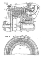
- a refiner 5 embodying the present invention includes a base 7 mounted on a suitable foundation 8 and supporting a refiner frame 9. At one end of the frame 9 is carried a housing 10 which has therein a refining chamber 11 providing a flow path for particulate material to be refined while travelling between an upstream inlet 12 and a downstream outlet 13.
- the material to be refined and in particular low consistency paper pulp or stock, is pumped by suitable pumping means (not shown) through a pipe 14 connected with the inlet 12.
- a refining assembly 15 is located in the chamber 11 across the flow path between the inlet 12 and the outlet 13. Refined material is discharged through the outlet 13 to a pipe 17 which conveys the refined material to a point of further treatment or to the headbox of a paper making machine.
- Paper making pulp stock in the form of a slurry of a consistency of from 1% to 8% is adapted to be efficiently refined by the refining assembly 15, comprising a unique, compact arrangement of a series of relatively rotatably cooperative axially confronting annular refining surfaces 18 and 19 which define radially extending refining zones 20 therebetween.
- the refining surfaces 18 and 19 comprise axially oppositely facing surfaces on annular generally internested refining disks 21 and 22 which, in effect, are in a longitudinally stacked assembly or pack.
- the disks.21 and 22 In the refining process, the disks.21 and 22 must be caused to rotate relatively. Either or both of the sets of disks 21 and 22 may be rotatably mounted.
- the disks 21 may be stator disks, fixed at radially outer edges thereof to an annular longitudinally elongate wall member 23 forming part of the refining chamber housing 10.
- the housing member 23 At its axially inner end, the housing member 23 has means comprising a radially outwardly extending annular flange 24 secured as by means of screws 25 to a radially outwardly extending annular frame portion 27.
- the member 23 has a radially outwardly extending annular attachment flange 28 which has secured thereto as by means of screws 29 an enclosure or cover 30 for the chamber 11.
- the inlet 12 is formed in the cover 30.
- the cover 30 is provided with radially extending reinforcing ribs 31, and the longitudinal housing member 23 is provided with longitudinally extending circumferentially spaced, radially projecting reinforcing ribs 32.
- stator refining rings 21 are maintained concentric by engagement with a cylindrical inner surface 33 provided by the housing member 23.
- Means comprising a longitudinal key 34 retains the disks 21 against torsional displacement relative to one another and to the surface 33.
- the disks 21 are held in preferably snug face-to-face engagement in their stack set by means comprising an annular axially outwardly facing shoulder 35 adjacent to the axially inner end of the housing member 23 and against which shoulder the axially intermost of the disks 21 thrusts under axially inward thrusting bias effected by means of an annular thrusting shoulder 37 on the cover 30.
- the shoulder 37 is drawn up firmly against the axially outermost of the disks 21 and which thereby transmits the disk compacting thrust to all of the other of the disks 21 in the stack.
- the refining disks 22 are mounted corotatably on a rotor 38 which is rotatably mounted on a shaft 39 supported by bearing means 40 mounted to the housing 9.
- Driving of the shaft 39 is adapted to be effected in any suitable means such as by an electrical motor (not shown) coupled to a shaft terminal 41 at the axially opposite end of the shaft from the rotor 38.
- the rotor 38 comprises a circular axially facing body plate 42 which is secured concentrically to the contiguous end of the shaft 39 as by means of screws 43. Carried coaxially by the perimeter of the body plate 42 is means in the form of a rigidly fixedly attached axially elongate cylindrical disk-mounting member 44.
- the rotor body plate 42 and the mounting cylinder 44 are of as thin a section as suitable for the purpose and reinforced by radially extending reinforcing ribs 45 attached to the axially outer face of the body plate 42 and to the radially inner perimeter of the cylinder 44.
- the disk mounting cylinder 44 On its radially outer perimeter, the disk mounting cylinder 44 has a cylindrical surface 47 (Fig.3) with which the radially inner edges of the refining disks 22 are concentrically engaged.
- a firmly stacked retention of the refining disks 22 on the mounting cylinder 44 is effected by thrusting the radially inner margin of the axially innermost of the disks 22 against an annular radially outwardly projecting shoulder 49 at the axially inner end of the mounting cylinder 44.
- Firm stack packing, axially inward thrusting of the disks 22 is effected by means of an annular thrust shoulder 50 provided on the outer margin of a closure disk plate 51 which is secured concentrically on the axially outer end of the rotor 38 as by means of take up screws 52 threadedly engaged in the axially outer end of the cylinder 44.
- the closure plate 51 cooperates with the adjacent inner face of the cover 30 to confine the area of the refining chamber 11 between the plate 51 and the cover 30 to a relatively narrow intake flow gap leading incoming material to be refined from the inlet 12 toward the refining assembly 15.
- optimum refining results are achieved per unit of energy input by seriatim refining action in the refining zones 20 from one end of the refining assembly 15 to the other end of the refining assembly 15.
- the radially opposite ends of the refining zones 20 are closed, and the particulate material to be refined is caused to pass successively between the radially opposite ends of the adjacent zones 20, and in one desirable arrangement, as shown, from the radially outer ends of upstream zones to the radially inner ends of the next adjacent downstream zones in the flow pattern from one end to the opposite end of the refining assembly 15.
- the direction of flow through the assembly 15 may be opposite to that specifically shown, if the inlet 12 becomes the outlet and the outlet 13 becomes the inlet.
- Closure of the radially opposite ends of the several refining zones 20 is effected by having the anchored margins of the two cooperating sets of disks 21 and 22 in firm abutment, and the refining surfaces 18 and 19 extending throughout an annular area on the respective disks extending from the free edges of the disks to the annular margins but substantially short of the respective mounting edges of the disks. Therefore, there is provided by the abutting faces of the anchored disk margins effective closure means for the radially opposite ends of the refining zones 20.
- the transfer passages 53 are provided by and between complementary spaced surfaces 54 and 55 on the backside, confronting surfaces of the disks 21 and 22, respectively.
- the complementary passage surfaces 54 and 55 are of generally planar oblique width throughout their major extent and then/with arcuate edges running out at the opposite ends of the surfaces.
- each of the passages 53 has a radially outer, upstream entrance which is aligned with the radially outer, downstream end of one of the refining zones 20, while the opposite, radially inner downstream end of the passage is aligned with the radially inner, upstream end of one of the refining zones 20.
- a narrow annular entrance port 57 from the upstream end of the chamber 11 is defined between the perimeter of the closure plate 51 and the radially inner edge of the adjacent refining disk 21.
- the annular exit port 58 is defined in alignment with the discharge end of the associated refining zone 20 by means of the radially outer edge of the axially innermost of the refining disks 22 and an annular tubular flange 59 telescopically engaged within the axially inner end portion of the housing member 23.
- the flange 59 is part of an axially inner closure member 60 for the refining chamber 11. It is this member 60 that has the outlet 13.
- an annular radially outwardly projecting rib 61 on the flange 59 is received in an annular rabbet groove 62 in the adjacent end of the member 23 and confined by the adjacent portion of the frame element 27.
- the material being refined is under dynamic pump pressure.
- at least some flow-through impulsion assistance may be afforded by the relatively rotating refining disks 21 and 22, at least to the extent that the flow through the refining assembly 15 will be free from back pressure and thus free from energy consuming loading of the rotor 38.
- maximum product return for energy input is attained. This is important when it is considered that for maximum efficiency in refining low consistency pulp stock, a desirable peripheral disk speed for the rotor-mounted disks 22 may be on the order of 150 to 250 m/s.
- the refining surfaces 18 and 19 are provided with generally radially extending refining bars 63, which may extend in straight radial direction, but are preferably relatively angled or biased in respectively opposite directions on the confronting refining surfaces.
- the refining bars 63 on the refining surfaces 18 desirably are biased in the direction of rotation of the rotor 38, that is clockwise as viewed in Fig. 3, while the refining bars 63 on the refining surfaces 19 on the rotor disks 22 are angled or biased in the opposite or counterclockwise direction as viewed in Fig. 3.
- the refining bars 63 may be 0,16 cm wide and 0,16 cm high, and with a 0,48 cm space between each pair of bars. With such an arrangement the circulating energy is reduced significantly.
- an optimum, relation of disk pairs to refining speed can be selected to optimize capital and operating costs.
- the rotor 38 is adapted to be axially adjustable as permitted by the spacing providing the oblique annular passages 53 between the respective pairs of the disks 21 and 22.
- the rotor shaft 39 is adapted to be axially shiftably adjustable in the bearing 40, appropriate adjustment gearing including a gear motor 64 being selectively operable to attain the desire axial adjustment.
- the shaft 39 extends into the refining chamber 11 through a shaft port 65 provided by the enclosure 60, a packing 67 being maintained under leak-preventing compression about the shaft by means of a pressure ring 68.
- a gap is defined between a diagonal block-off plate ring 69 mounted on the rotor and a spaced confronting diagonal block-off plate ring 70 carried by the closure 60 within the refining chamber 11. Since the chamber area between the plates 69 and 70 is biased toward the outlet 13, constant flushing of the area at the inner end of the rotor 38 prevents material accumulation.
- the present invention provides significant improvements over prior refiners,_especially for refining low consistency pulp or stock for paper making purposes.
- the refining chamber housing 10 and the refining assembly 15 are simple and rugged, and adapted for low cost production and convenient, easy assembly.
- the refining assembly disks 21 and 22 are easily accessible if necessary, simply by removal of the outer end cover 30 and may be pulled as a unit from the refining chamber 11 by simply removing the closure and retaining plate 51, detaching the rotor 38 from the shaft 39 and pulling out the whole assembly if desired.
- the disks 21 and 22 can nevertheless be removed and replaced simply by removing the retaining closure plate 51 after removing the cover 30 and then pulling the disks out one after the other. Mounting of the refining assembly is equally easy.
Landscapes
- Paper (AREA)
- Crushing And Grinding (AREA)
Applications Claiming Priority (2)
| Application Number | Priority Date | Filing Date | Title |
|---|---|---|---|
| US06/486,005 US4529137A (en) | 1983-04-18 | 1983-04-18 | Multiple disk refiner for low consistency refining of mechanical pulp |
| US486005 | 1990-02-26 |
Publications (2)
| Publication Number | Publication Date |
|---|---|
| EP0122868A2 true EP0122868A2 (de) | 1984-10-24 |
| EP0122868A3 EP0122868A3 (de) | 1985-07-03 |
Family
ID=23930237
Family Applications (1)
| Application Number | Title | Priority Date | Filing Date |
|---|---|---|---|
| EP84630055A Withdrawn EP0122868A3 (de) | 1983-04-18 | 1984-04-03 | Mehrscheibenrefiner zum Mahlen von Papierfaserstoff geringer Dichte |
Country Status (12)
| Country | Link |
|---|---|
| US (1) | US4529137A (de) |
| EP (1) | EP0122868A3 (de) |
| JP (1) | JPS59199893A (de) |
| KR (1) | KR860001616B1 (de) |
| BR (1) | BR8401673A (de) |
| DE (1) | DE122868T1 (de) |
| ES (1) | ES8507638A1 (de) |
| FI (1) | FI841418A7 (de) |
| IN (1) | IN163072B (de) |
| NO (1) | NO841393L (de) |
| PH (1) | PH21090A (de) |
| ZA (1) | ZA842462B (de) |
Families Citing this family (9)
| Publication number | Priority date | Publication date | Assignee | Title |
|---|---|---|---|---|
| US5425508A (en) * | 1994-02-17 | 1995-06-20 | Beloit Technologies, Inc. | High flow, low intensity plate for disc refiner |
| US5467931A (en) * | 1994-02-22 | 1995-11-21 | Beloit Technologies, Inc. | Long life refiner disc |
| US5823453A (en) * | 1995-11-14 | 1998-10-20 | J & L Fiber Services, Inc. | Refiner disc with curved refiner bars |
| WO1998009018A1 (en) * | 1996-08-26 | 1998-03-05 | Beloit Technologies, Inc. | Refiner having center ring with replaceable vanes |
| US5988538A (en) * | 1998-07-28 | 1999-11-23 | J&L Fiber Services, Inc. | Refiner disc having steam exhaust channel |
| SE513140C2 (sv) * | 1998-11-19 | 2000-07-10 | Valmet Fibertech Ab | Förfarande för framställning av uppgraderad tidningspappersmassa till SC/LWC kvalitet |
| US6572037B1 (en) | 1999-02-04 | 2003-06-03 | Mct Holdings, Llc | Shredder with parts ejector |
| US7188792B2 (en) * | 2003-03-18 | 2007-03-13 | Gl&V Management Hungary Kft. | Refiner rotor assembly with a hub having flow-through ports |
| PL3140454T3 (pl) | 2014-05-07 | 2020-06-01 | University Of Maine System Board Of Trustees | Wysokowydajne wytwarzanie nanofibrylowanej celulozy |
Family Cites Families (8)
| Publication number | Priority date | Publication date | Assignee | Title |
|---|---|---|---|---|
| CA527395A (en) * | 1956-07-10 | Reisten Werner | Mill for fibrous substances | |
| AT23350B (de) * | 1904-07-05 | 1906-03-10 | James Hunter Annandale | Zerkleinerungsmaschine für Papierstoff u. dgl. |
| GB191126688A (en) * | 1911-11-29 | 1912-09-05 | William Stephenson Barron | Improvements in Grinding Mills. |
| US2718178A (en) * | 1948-02-04 | 1955-09-20 | Wandel Kurt | Machine for effecting a refining treatment of fibrous material |
| AT182602B (de) * | 1948-12-31 | 1955-07-25 | Werner Reisten | Mühle für die kontinuierliche Mahlung von Faserstoffen |
| FR1145532A (fr) * | 1956-03-06 | 1957-10-28 | Appareil pour le dépastillage et l'ouverture des fibres de cellulose utilisées dans la fabrication de la pâte à papier | |
| US3371873A (en) * | 1966-03-24 | 1968-03-05 | Keith V. Thomas | Refining apparatus |
| US4167250A (en) * | 1978-04-19 | 1979-09-11 | The United States Of America As Represented By The Secretary Of Agriculture | Sequential velocity disk refiner |
-
1983
- 1983-04-18 US US06/486,005 patent/US4529137A/en not_active Expired - Lifetime
-
1984
- 1984-04-02 ZA ZA842462A patent/ZA842462B/xx unknown
- 1984-04-03 EP EP84630055A patent/EP0122868A3/de not_active Withdrawn
- 1984-04-03 DE DE198484630055T patent/DE122868T1/de active Pending
- 1984-04-04 PH PH30498A patent/PH21090A/en unknown
- 1984-04-05 IN IN223/CAL/84A patent/IN163072B/en unknown
- 1984-04-09 NO NO841393A patent/NO841393L/no unknown
- 1984-04-10 FI FI841418A patent/FI841418A7/fi not_active Application Discontinuation
- 1984-04-10 BR BR8401673A patent/BR8401673A/pt unknown
- 1984-04-13 JP JP59073162A patent/JPS59199893A/ja active Granted
- 1984-04-17 ES ES531667A patent/ES8507638A1/es not_active Expired
- 1984-04-18 KR KR1019840002049A patent/KR860001616B1/ko not_active Expired
Also Published As
| Publication number | Publication date |
|---|---|
| FI841418A0 (fi) | 1984-04-10 |
| ZA842462B (en) | 1984-11-28 |
| KR860001616B1 (ko) | 1986-10-14 |
| KR840008405A (ko) | 1984-12-14 |
| US4529137A (en) | 1985-07-16 |
| PH21090A (en) | 1987-07-16 |
| DE122868T1 (de) | 1985-12-05 |
| JPS59199893A (ja) | 1984-11-13 |
| ES531667A0 (es) | 1985-10-01 |
| JPS6229554B2 (de) | 1987-06-26 |
| ES8507638A1 (es) | 1985-10-01 |
| NO841393L (no) | 1984-10-19 |
| EP0122868A3 (de) | 1985-07-03 |
| IN163072B (de) | 1988-08-06 |
| FI841418A7 (fi) | 1984-10-19 |
| BR8401673A (pt) | 1984-11-20 |
Similar Documents
| Publication | Publication Date | Title |
|---|---|---|
| DE60023658T2 (de) | Scheibenmühle mit tangentialem austritt | |
| EP0122868A2 (de) | Mehrscheibenrefiner zum Mahlen von Papierfaserstoff geringer Dichte | |
| CN112501940B (zh) | 精磨机刀片元件 | |
| GB2026897A (en) | Beater for treating fibre slurries or lumpy materials | |
| US4619414A (en) | Multi-disk refiner | |
| CA1240191A (en) | Composite flexible pulp refiner disk and method of making the same | |
| GB2083375A (en) | Disc mills | |
| US4531681A (en) | Flexible disk refiner and method | |
| US4383918A (en) | High turbulence screen | |
| US5813618A (en) | Continuous cyclindrical wood pulp refiner | |
| CA1309978C (en) | Sorting apparatus for fiber suspensions | |
| AU579908B2 (en) | Rotor/mixer for controlling mixing and refining of pulp material | |
| US3552664A (en) | Disc-type | |
| JPS6071792A (ja) | デイスクリフアイナー | |
| FI68873B (fi) | Trumraffinoer | |
| FI90259B (fi) | Rumpuraffinööri kuituainemateriaalin hienontamiseksi tai jauhamiseksi | |
| CA1180686A (en) | Paper making stock screening apparatus incorporating circular apertured cylindrical pressure screen | |
| US5047118A (en) | Method for decreasing energy consumption during refining of fiber material at a reduced grinding frequency while maintaining capacity | |
| US5152871A (en) | Method for decreasing energy consumption during refining of fiber material while maintaining capacity | |
| CA1306378C (en) | Method for decreasing energy consumption during refining of fiber material while maintaining capacity | |
| US3162385A (en) | Paper making pulp refiner | |
| EP0919662A2 (de) | Scheibenmühle für Papierfaserstoff | |
| IT202300007326A1 (it) | Metodo ed impianto per la raffinazione in pasta densa di pulp per la produzione della carta |
Legal Events
| Date | Code | Title | Description |
|---|---|---|---|
| PUAI | Public reference made under article 153(3) epc to a published international application that has entered the european phase |
Free format text: ORIGINAL CODE: 0009012 |
|
| AK | Designated contracting states |
Designated state(s): AT DE FR GB IT NL SE |
|
| PUAL | Search report despatched |
Free format text: ORIGINAL CODE: 0009013 |
|
| AK | Designated contracting states |
Designated state(s): AT DE FR GB IT NL SE |
|
| ITCL | It: translation for ep claims filed |
Representative=s name: RICCARDI SERGIO & CO. |
|
| TCAT | At: translation of patent claims filed | ||
| TCNL | Nl: translation of patent claims filed | ||
| EL | Fr: translation of claims filed | ||
| DET | De: translation of patent claims | ||
| 17P | Request for examination filed |
Effective date: 19860103 |
|
| 17Q | First examination report despatched |
Effective date: 19870130 |
|
| STAA | Information on the status of an ep patent application or granted ep patent |
Free format text: STATUS: THE APPLICATION HAS BEEN WITHDRAWN |
|
| 18W | Application withdrawn |
Withdrawal date: 19871207 |
|
| RIN1 | Information on inventor provided before grant (corrected) |
Inventor name: ROBINSON, DAVID H. Inventor name: MATHEW, JOHN B. |