EP0122965A2 - Portail coulissant - Google Patents
Portail coulissant Download PDFInfo
- Publication number
- EP0122965A2 EP0122965A2 EP83111780A EP83111780A EP0122965A2 EP 0122965 A2 EP0122965 A2 EP 0122965A2 EP 83111780 A EP83111780 A EP 83111780A EP 83111780 A EP83111780 A EP 83111780A EP 0122965 A2 EP0122965 A2 EP 0122965A2
- Authority
- EP
- European Patent Office
- Prior art keywords
- rollers
- rotatably mounted
- pressure rollers
- bearing block
- sliding gate
- Prior art date
- Legal status (The legal status is an assumption and is not a legal conclusion. Google has not performed a legal analysis and makes no representation as to the accuracy of the status listed.)
- Granted
Links
Images


Classifications
-
- E—FIXED CONSTRUCTIONS
- E05—LOCKS; KEYS; WINDOW OR DOOR FITTINGS; SAFES
- E05D—HINGES OR SUSPENSION DEVICES FOR DOORS, WINDOWS OR WINGS
- E05D15/00—Suspension arrangements for wings
- E05D15/06—Suspension arrangements for wings for wings sliding horizontally more or less in their own plane
- E05D15/0617—Suspension arrangements for wings for wings sliding horizontally more or less in their own plane of cantilever type
-
- E—FIXED CONSTRUCTIONS
- E05—LOCKS; KEYS; WINDOW OR DOOR FITTINGS; SAFES
- E05D—HINGES OR SUSPENSION DEVICES FOR DOORS, WINDOWS OR WINGS
- E05D15/00—Suspension arrangements for wings
- E05D15/06—Suspension arrangements for wings for wings sliding horizontally more or less in their own plane
- E05D15/0621—Details, e.g. suspension or supporting guides
- E05D15/066—Details, e.g. suspension or supporting guides for wings supported at the bottom
- E05D15/0665—Details, e.g. suspension or supporting guides for wings supported at the bottom on wheels with fixed axis
-
- E—FIXED CONSTRUCTIONS
- E05—LOCKS; KEYS; WINDOW OR DOOR FITTINGS; SAFES
- E05F—DEVICES FOR MOVING WINGS INTO OPEN OR CLOSED POSITION; CHECKS FOR WINGS; WING FITTINGS NOT OTHERWISE PROVIDED FOR, CONCERNED WITH THE FUNCTIONING OF THE WING
- E05F15/00—Power-operated mechanisms for wings
- E05F15/60—Power-operated mechanisms for wings using electrical actuators
- E05F15/603—Power-operated mechanisms for wings using electrical actuators using rotary electromotors
- E05F15/632—Power-operated mechanisms for wings using electrical actuators using rotary electromotors for horizontally-sliding wings
- E05F15/635—Power-operated mechanisms for wings using electrical actuators using rotary electromotors for horizontally-sliding wings operated by push-pull mechanisms, e.g. flexible or rigid rack-and-pinion arrangements
- E05F15/641—Power-operated mechanisms for wings using electrical actuators using rotary electromotors for horizontally-sliding wings operated by push-pull mechanisms, e.g. flexible or rigid rack-and-pinion arrangements operated by friction wheels
-
- E—FIXED CONSTRUCTIONS
- E05—LOCKS; KEYS; WINDOW OR DOOR FITTINGS; SAFES
- E05F—DEVICES FOR MOVING WINGS INTO OPEN OR CLOSED POSITION; CHECKS FOR WINGS; WING FITTINGS NOT OTHERWISE PROVIDED FOR, CONCERNED WITH THE FUNCTIONING OF THE WING
- E05F15/00—Power-operated mechanisms for wings
- E05F15/60—Power-operated mechanisms for wings using electrical actuators
- E05F15/603—Power-operated mechanisms for wings using electrical actuators using rotary electromotors
- E05F15/632—Power-operated mechanisms for wings using electrical actuators using rotary electromotors for horizontally-sliding wings
- E05F15/643—Power-operated mechanisms for wings using electrical actuators using rotary electromotors for horizontally-sliding wings operated by flexible elongated pulling elements, e.g. belts, chains or cables
-
- E—FIXED CONSTRUCTIONS
- E05—LOCKS; KEYS; WINDOW OR DOOR FITTINGS; SAFES
- E05Y—INDEXING SCHEME ASSOCIATED WITH SUBCLASSES E05D AND E05F, RELATING TO CONSTRUCTION ELEMENTS, ELECTRIC CONTROL, POWER SUPPLY, POWER SIGNAL OR TRANSMISSION, USER INTERFACES, MOUNTING OR COUPLING, DETAILS, ACCESSORIES, AUXILIARY OPERATIONS NOT OTHERWISE PROVIDED FOR, APPLICATION THEREOF
- E05Y2201/00—Constructional elements; Accessories therefor
- E05Y2201/60—Suspension or transmission members; Accessories therefor
- E05Y2201/622—Suspension or transmission members elements
- E05Y2201/674—Friction wheels
-
- E—FIXED CONSTRUCTIONS
- E05—LOCKS; KEYS; WINDOW OR DOOR FITTINGS; SAFES
- E05Y—INDEXING SCHEME ASSOCIATED WITH SUBCLASSES E05D AND E05F, RELATING TO CONSTRUCTION ELEMENTS, ELECTRIC CONTROL, POWER SUPPLY, POWER SIGNAL OR TRANSMISSION, USER INTERFACES, MOUNTING OR COUPLING, DETAILS, ACCESSORIES, AUXILIARY OPERATIONS NOT OTHERWISE PROVIDED FOR, APPLICATION THEREOF
- E05Y2800/00—Details, accessories and auxiliary operations not otherwise provided for
- E05Y2800/20—Combinations of elements
- E05Y2800/21—Combinations of elements of identical elements, e.g. of identical compression springs
-
- E—FIXED CONSTRUCTIONS
- E05—LOCKS; KEYS; WINDOW OR DOOR FITTINGS; SAFES
- E05Y—INDEXING SCHEME ASSOCIATED WITH SUBCLASSES E05D AND E05F, RELATING TO CONSTRUCTION ELEMENTS, ELECTRIC CONTROL, POWER SUPPLY, POWER SIGNAL OR TRANSMISSION, USER INTERFACES, MOUNTING OR COUPLING, DETAILS, ACCESSORIES, AUXILIARY OPERATIONS NOT OTHERWISE PROVIDED FOR, APPLICATION THEREOF
- E05Y2900/00—Application of doors, windows, wings or fittings thereof
- E05Y2900/40—Application of doors, windows, wings or fittings thereof for gates
- E05Y2900/402—Application of doors, windows, wings or fittings thereof for gates for cantilever gates
Definitions
- the invention relates to a sliding gate, consisting essentially of a guided sliding gate leaf with a lower horizontal flanges longitudinal spar on the undersides of which at least one rotatably mounted roller rests at least for supporting the gate leaf and attack pressure rollers on the upper sides thereof.
- Sliding gates of the type described in the introduction are known, for example, from GM 76 00 142. Such self-supporting sliding gates have proven their worth.
- a relatively high construction effort is required, which additionally requires precise manufacture and complex and precise assembly.
- This connection alone with the shaft for the drive roller is complex.
- exact parallelism between the bores for the axes of the pressure rollers and the shaft for the drive roller must be ensured in order to avoid obstacles. This forces high-precision manufacturing and extreme care during assembly.
- the assembly sequence is complex even with such an arrangement.
- the invention is therefore based on the object of proposing a sliding gate of the type described at the outset, which is drastically simplified in construction, manufacture and assembly expenditure and nevertheless ensures the necessary safety and stability in the guidance of a self-supporting gate leaf.
- this task is for a sliding gate Type described in the introduction solved in that at least two pairs of pressure rollers are arranged symmetrically distributed to rotatably mounted rollers, one pair each being mounted in a common bearing block, which in turn is movably connected in the articulated eye of an eyebolt to a stationary part or to the foundation.
- the pressure rollers themselves are movably mounted, so that the complex assembly and precise manufacture for the respective brackets is avoided.
- the pressure rollers themselves are no longer attached with their brackets to the shaft for a drive or support roller, but directly with a stationary part or with the foundation, which also simplifies the sequence of assembly and the overall assembly effort.
- each other two rotatably mounted rollers are provided at least for support, wherein a pair of drive rollers is provided in each case outside the spaces between the two rotatably mounted rollers and in the vicinity of each of these rollers.
- Another embodiment of the invention provides that at least one further pair of pressure rollers is provided in the space between the rotatably mounted rollers. This further minimizes the construction effort.
- Another embodiment of the invention in turn provides that two pairs of pressure rollers are provided for each rotatably mounted roller. In this way, particularly great guidance stability is achieved in cases of particularly high loads.
- each roller of a pair of pressure rollers is divided and arranged on a common axis, this axis being mounted in a bearing block part which in turn is connected to a second bearing block part via an axis mounted in the articulated eye of the eyebolt and is combined into a storage block.
- the construction described is particularly simple to produce and significantly facilitates the Intelmonta g e and makes the exchange of small worn items possible.
- each roller Plastic or rubber At least the running surface of each roller Plastic or rubber. In this way, at least when the gate wing is made of non-ferrous metals, actuation which is wear-free for the gate wing is achieved.
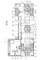
- a shaft 35 is mounted in the bearing blocks 31 and 32 and a shaft 36 is rotatably mounted in the bearing blocks 33 and 34.
- a roller 7 is arranged on the shaft 35 in a rotationally fixed manner and a roller 8 is arranged on the shaft 36 in a rotationally fixed manner.
- a sprocket 39 or 38 is connected in a rotationally fixed manner to the shaft 35 and the shaft 36. Both chain wheels are connected to one another via the chain 40.
- the shaft 36 also has a coupling 37 connected to it in a rotationally fixed manner. The coupling 37 is suitable for connecting the shaft 36 to a desired drive device.
- the gate wing 28 lies on the rollers 7 and 8 with the horizontal flanges 30 of its longitudinal spar 29. If the above-mentioned rollers are driven in rotation, the gate leaf 28, which due to its weight makes the necessary frictional contact with the rollers 7 and 8, is shifted accordingly. However, in this arrangement it would on the one hand have friction applied displacement force in many cases would not be sufficient and also the gate wing 28, which is cantilevered, would tip over in the extended position or, depending on the weight, also earlier. The transferable friction forces are improved and the risk of tipping is eliminated by pressure rollers 3, 4, 5, 6, 5 ', 6', which are arranged on the top of the horizontal flanges 30 in the longitudinal spar 29 of the gate leaf 28 and run there.
- the pressure rollers mentioned should press the horizontal flanges 30 onto the rollers 7 and 8 on the one hand, so that an increase in the transferable frictional forces is achieved but the possibility of slipping through is retained for safety reasons, and on the other hand they should tilt the gate leaf 28 due to their special arrangement to make impossible. They should be simple in construction and simple to manufacture and also easy to assemble and replace, but without sacrificing functional reliability.
- the pressure members are combined into pairs 1, 2, 2 ', pair 1 and pair 2 being arranged outside the gap 25, while a further pair 2' are arranged, for example, in the middle of the gap 25 can be.
- the pair 2 'of the pressure rollers is not always necessary.
- pairs 26 and 27 are also possible, in addition or as an alternative to pair 2 ', to provide 25 further pairs 26 and 27 of pressure rollers within the intermediate space. These positions are indicated by the arrows shown in FIG. 1 with the reference numerals 26 and 27. These pairs 26 and 27 can also be provided either alternatively or in addition to pairs 1 and 2. These arrangement options allow different door sizes and door loads to be taken into account.
- Each roller 3 and 4 of the pair of rollers 1 is in the longitudinal direction divided and rotatably mounted on a common axis, which is arranged in the bearing block part 9 or 10.
- the same also applies to the rollers 5 'and 6', whose common axes are held in the bearing block parts 12 'and 13'.
- the mentioned bearing block parts in turn each have an axis 11 or 14 or 14 'perpendicular to the axes of the rollers, the axes mentioned connecting two bearing block parts to one another.
- the axes themselves are in this case articulated in a joint eye 15 or 16 or 17 of an eye screw 18 or 19 or 20.
- the eyebolt 18 is attached with the free end to a stationary part 21, the eyebolt 19 with its free end to a stationary part 22 and the eyebolt 20 with its free end to a stationary part 23, for example screwed.
- By means of the screw connection it is possible to position each eye screw 18, 19, 20 in the vertical direction, so that the holding and pressing force of the pressure rollers described can be adjusted.
- all the rollers described above are made of plastic or rubber or have at least one covering of at least the running surfaces made of plastic or rubber.
- this reduces rolling noise and, on the other hand, the transmissible frictional forces are increased with less pressing force and damage to at least the
- the longitudinal spar 29 of the gate wing 28 is prevented by the rollers, in particular by the rollers 7 and 8, which is particularly advantageous when the entire gate wing 28, but at least the longitudinal spar 29, is made of a non-ferrous metal.
Landscapes
- Engineering & Computer Science (AREA)
- Mechanical Engineering (AREA)
- Gates (AREA)
Applications Claiming Priority (2)
| Application Number | Priority Date | Filing Date | Title |
|---|---|---|---|
| DE19838312031U DE8312031U1 (de) | 1983-04-23 | 1983-04-23 | Schiebetor |
| DE8312031U | 1983-04-23 |
Publications (3)
| Publication Number | Publication Date |
|---|---|
| EP0122965A2 true EP0122965A2 (fr) | 1984-10-31 |
| EP0122965A3 EP0122965A3 (en) | 1985-12-27 |
| EP0122965B1 EP0122965B1 (fr) | 1988-04-27 |
Family
ID=6752646
Family Applications (1)
| Application Number | Title | Priority Date | Filing Date |
|---|---|---|---|
| EP83111780A Expired EP0122965B1 (fr) | 1983-04-23 | 1983-11-24 | Portail coulissant |
Country Status (2)
| Country | Link |
|---|---|
| EP (1) | EP0122965B1 (fr) |
| DE (2) | DE8312031U1 (fr) |
Cited By (2)
| Publication number | Priority date | Publication date | Assignee | Title |
|---|---|---|---|---|
| EP0596362A3 (fr) * | 1992-11-02 | 1994-12-28 | Huegle Pfullendorf Kipptor | Porte coulissante en porte à faux. |
| GB2451110A (en) * | 2007-07-18 | 2009-01-21 | Parking Facilities Ltd | Cantilever gate having an external drive system |
Families Citing this family (2)
| Publication number | Priority date | Publication date | Assignee | Title |
|---|---|---|---|---|
| DE19531092C2 (de) * | 1995-08-24 | 2000-02-17 | Hespe & Woelm Gmbh & Co Kg | Schiebetoranlage |
| GB2639833A (en) * | 2024-03-22 | 2025-10-08 | Edgesmith Ltd | Self-levelling support for cantilevered sliding gate |
Family Cites Families (5)
| Publication number | Priority date | Publication date | Assignee | Title |
|---|---|---|---|---|
| DE838615C (de) * | 1950-06-04 | 1952-05-12 | Ver Baubeschlag Gretsch Co | Rollenlaufwerk fuer Schiebetueren, insbesondere fuer Schienenfahrzeuge |
| DE1559961C3 (de) * | 1966-10-13 | 1973-11-22 | Carola Dr. 3327 Salzgitter-Bad Malkmus-Doernemann Geb. Doernemann | Freitragendes Schiebetor |
| DE1683259C3 (de) * | 1966-12-07 | 1974-11-21 | Carola Dr. 3320 Salzgitter Malkmus-Doernemann Geb. Doernemann | Freitragendes Schiebetor |
| GB1405931A (en) * | 1972-05-26 | 1975-09-10 | Henderson P C Ltd | Hangers for sliding doors |
| DE7600142U1 (de) * | 1976-01-07 | 1976-05-20 | Juma-Bauelemente Gmbh & Co Kg, 5160 Dueren | Freitragendes schiebetor |
-
1983
- 1983-04-23 DE DE19838312031U patent/DE8312031U1/de not_active Expired
- 1983-11-24 DE DE8383111780T patent/DE3376440D1/de not_active Expired
- 1983-11-24 EP EP83111780A patent/EP0122965B1/fr not_active Expired
Cited By (3)
| Publication number | Priority date | Publication date | Assignee | Title |
|---|---|---|---|---|
| EP0596362A3 (fr) * | 1992-11-02 | 1994-12-28 | Huegle Pfullendorf Kipptor | Porte coulissante en porte à faux. |
| GB2451110A (en) * | 2007-07-18 | 2009-01-21 | Parking Facilities Ltd | Cantilever gate having an external drive system |
| WO2009010798A1 (fr) * | 2007-07-18 | 2009-01-22 | Parking Facilities Ltd | Appareil de barrière en porte à faux |
Also Published As
| Publication number | Publication date |
|---|---|
| DE8312031U1 (de) | 1983-09-29 |
| EP0122965B1 (fr) | 1988-04-27 |
| EP0122965A3 (en) | 1985-12-27 |
| DE3376440D1 (de) | 1988-06-01 |
Similar Documents
| Publication | Publication Date | Title |
|---|---|---|
| EP1518817B1 (fr) | Chariot roulant, en particulier chariot roulant monorail de faible hauteur | |
| DE10145476B4 (de) | Freies Gelenkarmsystem füe eine präzise Kontrolle | |
| DE9418079U1 (de) | Freitragendes Schiebetor | |
| DE3026904C2 (de) | Verschiebbare Lagerung für ein Wellen- bzw. Walzenlager | |
| EP0356761A1 (fr) | Dispositif de levage à ciseaux, en particulier pour une plate-forme de travail | |
| EP0122965B1 (fr) | Portail coulissant | |
| EP0207184A1 (fr) | Transmission à friction à rouleaux pivotants | |
| DE3523187A1 (de) | Gebaeudeaufzug | |
| DE2237991A1 (de) | Axialdrucklager in tandemanordnung | |
| EP1090696B1 (fr) | Dispositif d'entrainement à chaines pour tréfilage en continu | |
| EP1108906B1 (fr) | Dispositif de guide lineaire | |
| DE2461773A1 (de) | Stellgeraet mit spindelmutter | |
| DE69507133T2 (de) | Vorrichtung bei hängeförderern | |
| WO2001047791A1 (fr) | Convoyeur a rouleaux servant a transporter et a positionner des articles a transporter | |
| DD252814A1 (de) | Scherenhubtisch | |
| DE3108552A1 (de) | Vorrichtung zur parallelverschiebung zweier in einander beabstandeten, parallelen ebenen liegenden tragelemente an hebezeugen oder foerdereinrichtungen | |
| DE69408072T2 (de) | Vorrichtung zum Öffnen und Schliessen einer Klappe | |
| EP0283532B1 (fr) | Presse à couper et déformer à entraînement à genouillère hydro-mécanique | |
| DE2300858C3 (de) | Hebe- und Dreheinrichtung in einem Zweiwegfahrzeug | |
| EP0659677B1 (fr) | Chariot de grue | |
| DE69005640T2 (de) | Vertikalwalzwerk. | |
| DE3617194C2 (fr) | ||
| DE2161917C3 (de) | Verfahrbare, sowie heb- und senkbare Werkzeugträgerplatte oder Schiebetisch für Pressen | |
| DE3034833C2 (de) | Ofen mit Förderrollen | |
| EP0475901B1 (fr) | Elévateur à colonne |
Legal Events
| Date | Code | Title | Description |
|---|---|---|---|
| PUAI | Public reference made under article 153(3) epc to a published international application that has entered the european phase |
Free format text: ORIGINAL CODE: 0009012 |
|
| 17P | Request for examination filed |
Effective date: 19831216 |
|
| AK | Designated contracting states |
Designated state(s): BE CH DE FR LI |
|
| PUAL | Search report despatched |
Free format text: ORIGINAL CODE: 0009013 |
|
| AK | Designated contracting states |
Designated state(s): BE CH DE FR LI |
|
| 17Q | First examination report despatched |
Effective date: 19861203 |
|
| GRAA | (expected) grant |
Free format text: ORIGINAL CODE: 0009210 |
|
| AK | Designated contracting states |
Kind code of ref document: B1 Designated state(s): BE CH DE FR LI |
|
| REF | Corresponds to: |
Ref document number: 3376440 Country of ref document: DE Date of ref document: 19880601 |
|
| ET | Fr: translation filed | ||
| PG25 | Lapsed in a contracting state [announced via postgrant information from national office to epo] |
Ref country code: BE Effective date: 19881130 |
|
| PLBE | No opposition filed within time limit |
Free format text: ORIGINAL CODE: 0009261 |
|
| STAA | Information on the status of an ep patent application or granted ep patent |
Free format text: STATUS: NO OPPOSITION FILED WITHIN TIME LIMIT |
|
| 26N | No opposition filed | ||
| BERE | Be: lapsed |
Owner name: JUMA ELEMENTEBAU G.M.B.H. & CO. K.G. Effective date: 19881130 |
|
| PG25 | Lapsed in a contracting state [announced via postgrant information from national office to epo] |
Ref country code: FR Free format text: LAPSE BECAUSE OF NON-PAYMENT OF DUE FEES Effective date: 19890731 |
|
| REG | Reference to a national code |
Ref country code: FR Ref legal event code: ST |
|
| PGFP | Annual fee paid to national office [announced via postgrant information from national office to epo] |
Ref country code: CH Payment date: 19911014 Year of fee payment: 9 |
|
| PGFP | Annual fee paid to national office [announced via postgrant information from national office to epo] |
Ref country code: DE Payment date: 19920124 Year of fee payment: 9 |
|
| PG25 | Lapsed in a contracting state [announced via postgrant information from national office to epo] |
Ref country code: LI Effective date: 19921130 Ref country code: CH Effective date: 19921130 |
|
| REG | Reference to a national code |
Ref country code: CH Ref legal event code: PL |
|
| PG25 | Lapsed in a contracting state [announced via postgrant information from national office to epo] |
Ref country code: DE Effective date: 19930803 |