EP1090696B1 - Dispositif d'entrainement à chaines pour tréfilage en continu - Google Patents
Dispositif d'entrainement à chaines pour tréfilage en continu Download PDFInfo
- Publication number
- EP1090696B1 EP1090696B1 EP00120496A EP00120496A EP1090696B1 EP 1090696 B1 EP1090696 B1 EP 1090696B1 EP 00120496 A EP00120496 A EP 00120496A EP 00120496 A EP00120496 A EP 00120496A EP 1090696 B1 EP1090696 B1 EP 1090696B1
- Authority
- EP
- European Patent Office
- Prior art keywords
- chain
- accordance
- drawing machine
- guide
- idler rollers
- Prior art date
- Legal status (The legal status is an assumption and is not a legal conclusion. Google has not performed a legal analysis and makes no representation as to the accuracy of the status listed.)
- Expired - Lifetime
Links
Images



Classifications
-
- B—PERFORMING OPERATIONS; TRANSPORTING
- B21—MECHANICAL METAL-WORKING WITHOUT ESSENTIALLY REMOVING MATERIAL; PUNCHING METAL
- B21C—MANUFACTURE OF METAL SHEETS, WIRE, RODS, TUBES, PROFILES OR LIKE SEMI-MANUFACTURED PRODUCTS OTHERWISE THAN BY ROLLING; AUXILIARY OPERATIONS USED IN CONNECTION WITH METAL-WORKING WITHOUT ESSENTIALLY REMOVING MATERIAL
- B21C1/00—Manufacture of metal sheets, wire, rods, tubes or like semi-manufactured products by drawing
- B21C1/16—Metal drawing by machines or apparatus in which the drawing action is effected by means other than drums, e.g. by a longitudinally-moved carriage pulling or pushing the work or stock for making metal sheets, rods or tubes
- B21C1/27—Carriages; Drives
- B21C1/30—Drives, e.g. carriage-traversing mechanisms; Driving elements, e.g. drawing chains; Controlling the drive
Definitions
- the invention relates to a chain pulling machine for continuous pulling of rod and tubular drawn goods in particular according to the preamble of claim 1, in particular a chain pulling machine with at least two drive chains, each assigned to a common drawing section have interconnected tension members and the side of the Tension members provided means can be driven, the tension members on one side with a clamping jaw that can be pressed onto the drawing material and on one other side are provided with a sliding surface with which the tension members via rotating, load-bearing idler rollers on each drive chain support the assigned rigid roller guide.
- EP 0 548 723 B2 shows a generic chain pulling machine.
- the Tension links of the drive chains have on their back, i.e. who the Side facing away from the jaws on a sliding surface that acts like a roller bearing via a moving chain guided on a fixed, rigid roller guide of idler rollers.
- the clamping force is achieved by means of the idler rollers directly from the jaws over the sliding surfaces on the Transfer role guidance.
- To counteract the stresses, to counteract are the idler rollers arranged in the center, with all sliding surfaces of the arranged in series Tension members a single, opposite the rigid roller guide over the same width as the idler rollers and the roller guide width have extending sliding surface.
- the object of the invention is to provide an improved chain pulling machine create that is simple and allows high clamping forces.
- the idler rollers with the sliding surface and / or the roller guide interact via a divided contact surface and at the level of the contact surface division only by using the rollers guided guides are guided. That way one needs elaborate guide device on the sliding surface and / or the Roller guidance should not be provided, which increases the presentation costs significantly reduce. Maintenance of the machine is also easier because a fixed guide or a guide running with the tension members only is very difficult to access.
- roller guides for the drive chains by means of at least one essentially along the drawing line extending relief recess are divided into guideways. Since the Roller guides on which the idler rollers roll with tolerances are afflicted and in particular are never completely flat, they can Idler rollers better due to the relief recess Adjust the roller guide so that the effective load-bearing line of force increases.
- the sliding surface is also to achieve the same advantages Tension members by means of at least one relief recess in slideways divided. It is particularly preferred if the idler rollers themselves are designed so that, based on the entire width of all Slideways and slideways are slightly flexible, so that they adhere to existing tolerances in the guideways and slideways can adjust.
- the idler rollers move extend over at least two guideways, preferably thus one idler roller extends over all guideways.
- the idler rollers each Relief recess associated with circumferential taper.
- the So idler rollers experience depending on the location of the Relief cutouts, deliberate weakening or minimization of their Diameter, so that over the width of the idlers within limits elastic adjustment or elastic bend to compensate for the tolerances can take place within the guideways and sliding surfaces.
- the idler rollers are made of parallel roller sets, each guideway and / or Slideway is assigned to a roller set.
- the machine effort for that The guidance of the idler rollers or roller sets is reduced if the Roller sets are then connected to each other via roller cages, especially if the roller sets are designed as chains.
- the Guideways and slideways uniform and / or with the same width are opposite. It is also advantageous if at least one Relief recess, the roller guide and / or the sliding surface in the middle Splits. In a particularly preferred embodiment there are two Guideways and / or two slideways provided.
- the tension members can be connected by means of a connecting bolt be connected, on both sides of the tension members on the connecting bolt Rollers and / or tension pieces are arranged.
- An even one Force introduction and force distribution is favored when the jaws and the sliding surfaces on opposite, mutually parallel sides of the Tension members are arranged, the clamping jaws and the sliding surfaces or slideways can be integrated in one piece in the tension members.
- the idler rollers are formed at least from two side rollers on a common axis are stored.
- This arrangement is particularly cost-effective since it is compatible with Standard components can be realized and still have the same advantages as the arrangements described above.
- a spacer for example one on the axle arranged sleeve, may be provided.
- the Idler rollers are connected to a chain. Since the tabs of the Chain overlap partially, is a bend of the chain in the side Direction only possible to a limited extent. This creates in a simple way an outer guide of the idler rollers or the partial rollers. This outer Leadership can take on laterally acting managers.
- inner guide elements act laterally Executives can take up, where they run with the roles and are arranged at the level of the contact surface division and thereby in lateral Direction not effectively in contact with fixed guide elements come. Because the inner guide elements are independent Executives can take on internal components, which in In the form of fixed guide elements, to be dispensed with. By eliminating such fixed Among other things, management elements also released space, which in turn for a more compact design is available.
- Lateral executives are understood to mean forces that have a force component, which in the longitudinal direction to the The guiding surface has a fictitious orthogonal plane.
- the inner guide elements are advantageously parallel to the Sliding surface and between the sliding surface and the guide surface arranged.
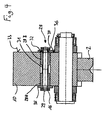
- Fig. 1 shows in principle the drive chain guide one essentially shown chain pulling machine.
- the drawn material designated 1 is between the jaws 2 of an endlessly rotating upper drive chain 3 and an endless rotating lower drive chain 4 is clamped.
- the Drive chains 3, 4 each consist of several identical to each other trained tension members 5A, 5B, which by means of a connecting bolt 6 are connected to one another, the clamping jaws 2 on the outside 5 ' the tension members 5A, 5B, based on the orbit of the drive chains 3, 4, are arranged.
- nuts 7 is the connection of the tension members 5A, 5B secured.
- the chain pulling machine has to drive the drive chains 3, 4 Spaced from each other, not shown here, sprockets, their teeth e.g. with the connecting bolts 6 directly or via pull pieces 5A interact. There are preferably two for each drive chain 3, 4 spaced sprockets between which the Drive chains 3,4 through and around. In this way it becomes a drive guaranteed laterally of the tension members.
- the drive chains 3, 4 are supported along a drawing line on which the Clamping jaws 2 are pressed against the drawn material 1 via idler rollers 8 one rigid, generally designated 9 and on the machine frame 10 arranged guide surface from.
- the guide surface 9 has a center Relief recess 11 that the guide surface 9 in a first Guideway 9A and a second guideway 9B divides.
- For the Rolling contact of the idler rollers 8 with the tension members 5A, 5B instruct them of the jaws 2, i.e. on the outside 5 'parallel opposite inner side 5 '' designated overall by 13 Sliding surface on which by means of a relief recess 14 in a first Slideway 13A and a second slideway 13B is divided.
- the continuous idler roller 8 which are preferably at least across the width of both guideways 9A, 9B or both slideways 13A, 13B, one Circumferential taper 15 in the form of a specially adapted groove or the like.
- the circumferential taper 15 ensures that the idler roller 8 bend elastically and thereby with their flat sections 8A, 8B optimally to the guideways 9A, 9B and slideways 13A, 13B can create, so that the entire width of the sections 8A, 8B at the Support of the tension members 5A, 5B is available as a wing.
- the idler rollers 8 can special roles Be guides or, as shown, connected to tabs 16 Roller chains must be executed. Since the tabs 16 are in the immediate Surroundings of the connecting bolts 6 partially overlap each other and allow only a limited lateral bending of the roller chain, executives who act laterally can therefore partially compensate. The tabs 16 take the task of a direct external leadership true.
- the special guides can be internal Guide elements 31 may be formed. These inner guidance elements can accommodate laterally acting managers and thus the Hold idler rollers 8 in the area of the guideways 9. This can help fixed guide elements between the sliding surface 13 and Guide surface 9 are arranged to be dispensed with.
- the idler rollers 18 here consist of two sets of rollers 18A, 18B, consequently from parts divided over the guide surface or sliding surface individual idler rollers; the first roller set 18A is the guide and Assigned slideways 9A, 13A, the second roller set 18B is the Guide and slideways 9B, 13B assigned.
- the roller sets 18A, 18b can be interconnected, e.g. via roller cages (not shown), and / or the idler rollers 18 of the respective idler roller sets be connected to one another via tabs 16, as shown.
- tabs 16 can provide direct external guidance, since the Lateral executives can accommodate tabs. You can the inner guide elements 31 laterally acting managers record, so that fixed guide elements also in this alternative embodiment for a perfect function in the field of Pulling distance of the chain pulling machine is no longer required.
- the relief cutout is dispensed with, and the adaptability or flexibility of the idler rollers is due to the Spacer 30 between the partial rollers guaranteed.
- the Spacer 30 also represents an inner guide element 31 this embodiment is again based on fixed guide elements dispensed with, since the inner guide elements 31 act laterally Managers can accept. Because also in this embodiment side tabs 16 connect the idler rollers to each other, the Here too, tabs take on direct external guidance.
- the idler rollers 28 there are 28 for the idler rollers two partial rollers 28A and 28B are also provided, which are arranged on an axis 29 are arranged. Is between these two sub-rollers 28A and 28B again an inner guide element 31 is arranged. Also in this Embodiment are the idler rollers 28 as with side tabs 16 connected roller chains executed. Between the inward idler surface 32 of the tabs 16 and this opposite side surfaces 33 (side surface of the Machine frame 10) and 34 (outer lateral surface of idler rollers 28) and 36 (lateral surface of the tension members 5) is a guide tab 35 arranged. This guide tab 35 is made of a slidable material and keeps the tools in a preferred position.
- the glides Guide tab 35 in its inner upper region on the side surface 33 of the machine frame 10 and in its lower inner region on the lateral surface 36 of the tension members 5. On the outer lateral area is the guide tab 35 partially with the side tab 16 in Contact.
- the guide tabs 35 preferably take no or only very low tensile forces.
- Fig. 5 is a longitudinal section of a chain drawing machine 38 with an endless revolving upper drive chain 3 and an endless revolving lower Drive chain 4 shown.
- the tools run at a central axis 39 or the tension members of the two drive chains 3, 4 together such that they the drawn material 1 in the direction of arrow 40 from left to right through the Convey chain puller 38.
- One drive chain overflows two sprockets 41 and 42, each with one of the sprockets as a drive serves.
- the teeth of the chain wheels 41, 42 engage in the spaces between the connecting bolts 6 and thus act with the Connecting bolts 6 of the drive chains 3, 4 together.
- Between Tension members 5 and the machine frame 10 are the idler rollers 18 and 28 arranged. These idler rollers 18, 28 are particularly in the Work area 43 with the tension members and the machine frame 10 in Rolling contact and transfer the arising in the work area 43 Compressive forces on the machine frame 10.
- Two guideways and slideways are shown in the figures. It can also have several guideways and slideways or several Relief recesses can be arranged and the idler rollers are then with correspondingly provided with several circumferential tapers or as several Running roller sets executed.
Landscapes
- Engineering & Computer Science (AREA)
- Mechanical Engineering (AREA)
- Devices For Conveying Motion By Means Of Endless Flexible Members (AREA)
- Metal Extraction Processes (AREA)
- Forwarding And Storing Of Filamentary Material (AREA)
Claims (19)
- Banc d'étirage à chaíne pour l'étirage continu de produits mis en oeuvre sous forme de barres et de tubes de métal ou similaire, avec au moins deux chaínes d'entraínement aptes à être entraínées qui sont assignées à une distance d'étirage commune et comportent des maillons de traction qui sont reliés les uns aux autres et sont munis d'un côté d'une mâchoire de serrage destinée à être plaquée contre le produit mis en oeuvre et de l'autre côté d'une surface de roulement par laquelle les maillons de traction viennent en appui sur un dispositif de guidage à rouleaux fixe associé à chaque chaíne d'entraínement par le biais de rouleaux libres tournants et porteurs, caractérisé en ce que les rouleaux libres (8, 18, 28) interagissent avec la surface de roulement (13) et/ou le dispositif de guidage (9) par l'intermédiaire d'une surface de contact divisée et ne sont guidés à la hauteur de l'endroit de la division que par des guides (31) suiveurs de rouleaux (8, 18, 28).
- Banc d'étirage à chaíne selon la revendication 1, caractérisé en ce que les dispositifs de guidage à rouleaux (9) des chaínes d'entraínement (3; 4) et/ou la surface de roulement (13) des maillons de traction (5A, 5B) est partagée en chemins de guidage (9A, 9B) ou en chemins de roulement (13A, 13B) au moyen d'au moins une découpe de décharge (11, 14).
- Banc d'étirage à chaíne selon la revendication 1 ou 2, caractérisé en ce que les rouleaux libres (8) s'étendent sur au moins deux chemins de guidage (9A, 9B).
- Banc d'étirage à chaíne selon la revendication 3, caractérisé en ce que les rouleaux libres (8) comportent un rétrécissement circonférentiel (15) associé aux découpes de décharge (11, 14).
- Banc d'étirage à chaíne selon la revendication 4, caractérisé en ce que le rétrécissement circonférentiel (15) permet la flexion élastique limitée des rouleaux libres (8) sur leur largeur.
- Banc d'étirage à chaíne selon la revendication 1 ou 2, caractérisé en ce que les rouleaux libres (18) sont constitués par des ensembles de rouleaux porteurs (18A, 18B) guidés de manière à être parallèles, un ensemble de rouleaux porteurs (18A, 18B) étant associé à chaque chemin de guidage (9A, 9B) et/ou à chaque chemin de roulement (13A, 13B).
- Banc d'étirage à chaíne selon la revendication 6, caractérisé en ce que les ensembles de rouleaux porteurs sont reliés par des cages de rouleaux porteurs.
- Banc d'étirage à chaíne selon la revendication 6 ou 7, caractérisé en ce que les ensembles de rouleaux porteurs (18A, 18B) sont conformés en forme de chaínes.
- Banc d'étirage à chaíne selon l'une quelconque des revendications 2 à 8, caractérisé en ce que les chemins de guidage (9A, 9B) et les chemins de roulement (13A, 13B) sont de forme identique et/ou ont la même largeur et se font face.
- Banc d'étirage à chaíne selon l'une quelconque des revendications 1 à 9, caractérisé en ce qu' au moins une découpe de décharge (11, 14) partage le dispositif de guidage à rouleaux (9) et/ou la surface de roulement (13) en deux parties égales.
- Banc d'étirage à chaíne selon l'une quelconque des revendications 1 à 10, caractérisé en ce que sont prévus deux chemins de guidage (9A, 9B) et/ou deux chemins de roulement (13A, 13B).
- Banc d'étirage à chaíne selon l'une quelconque des revendications 1 à 11, caractérisé en ce que les maillons de traction (5A, 5B) sont reliés entre eux par un boulon de liaison (6), des rouleaux porteurs et/ou des pièces de traction étant disposés de part et d'autre des maillons de traction.
- Banc d'étirage à chaíne selon l'une quelconque des revendications 1 à 12, caractérisé en ce que les mâchoires de serrage (2) et les surfaces de roulement (13) sont disposées sur des faces (5', 5") des maillons de traction (5A, 5B) parallèles situées en regard l'une de l'autre.
- Banc d'étirage à chaíne selon l'une quelconque des revendications 1 à 13, caractérisé en ce que les mâchoires de serrage (2) et les surfaces de roulement (13) ou les chemins de roulement (13A, 13B) sont solidaires des maillons de traction (5A, 5B) dans lesquels ils sont intégrés.
- Banc d'étirage à chaíne selon l'une quelconque des revendications 1 à 14, caractérisé en ce que les rouleaux libres (28) sont constitués par au moins deux parties de rouleaux (28A, 28B) supportées par un axe (29) commun.
- Banc d'étirage à chaíne selon la revendication 15, caractérisé en ce qu' entre les parties de rouleaux (28A, 28B) est prévu un écarteur (30), par exemple un manchon disposé sur l'axe (29).
- Banc d'étirage à chaíne selon l'une quelconque des revendications 1 à 16, caractérisé en ce que les rouleaux libres (8, 18, 28) sont reliés entre eux de manière à former une chaíne.
- Banc d'étirage à chaíne selon l'une quelconque des revendications 1 à 17, caractérisé en ce que des éléments de guidage interne (31) encaissent des efforts de guidage latéraux, suivent les rouleaux (8, 18, 28), sont disposés à la hauteur de l'endroit (14) où la surface de contact est partagée et ne viennent pas en contact opérationnel latéral avec des éléments de guidage fixes.
- Banc d'étirage à chaíne selon l'une quelconque des revendications 1 à 18, caractérisé en ce que les ensembles de rouleaux porteurs (8, 18, 28) comportent des éléments de guidage internes (31) qui sont disposés entre la surface de roulement (13) et la surface de guidage (9) sans venir en contact opérationnel avec des groupes latéralement immobiles.
Applications Claiming Priority (2)
| Application Number | Priority Date | Filing Date | Title |
|---|---|---|---|
| DE19947806.6A DE19947806B4 (de) | 1999-10-05 | 1999-10-05 | Kettenziehmaschine zum kontinuierlichen Ziehen von Ziehgut |
| DE19947806 | 1999-10-05 |
Publications (4)
| Publication Number | Publication Date |
|---|---|
| EP1090696A2 EP1090696A2 (fr) | 2001-04-11 |
| EP1090696A3 EP1090696A3 (fr) | 2002-01-23 |
| EP1090696B1 true EP1090696B1 (fr) | 2004-09-01 |
| EP1090696B2 EP1090696B2 (fr) | 2009-07-22 |
Family
ID=7924474
Family Applications (1)
| Application Number | Title | Priority Date | Filing Date |
|---|---|---|---|
| EP00120496A Expired - Lifetime EP1090696B2 (fr) | 1999-10-05 | 2000-09-20 | Dispositif d'entrainement à chaines pour tréfilage en continu |
Country Status (5)
| Country | Link |
|---|---|
| US (1) | US6450386B1 (fr) |
| EP (1) | EP1090696B2 (fr) |
| JP (1) | JP4663865B2 (fr) |
| AT (1) | ATE275005T1 (fr) |
| DE (2) | DE19947806B4 (fr) |
Families Citing this family (9)
| Publication number | Priority date | Publication date | Assignee | Title |
|---|---|---|---|---|
| WO2002055227A1 (fr) * | 2001-01-11 | 2002-07-18 | Ejp Maschinen Gmbh | Machine a etirer |
| DE102004031843A1 (de) * | 2004-06-30 | 2006-01-26 | Schumag Ag | Ziehmaschine |
| US7682106B1 (en) | 2005-09-21 | 2010-03-23 | Larry Bowar | Apparatus for installing slipliners in pipes |
| DE102011010949A1 (de) * | 2011-02-10 | 2012-08-16 | Weber Schweißmaschinen GmbH | Drahtvorschubsystem |
| DE102018111731A1 (de) * | 2017-05-26 | 2018-11-29 | Sms Group Gmbh | Raupenzugziehmaschine und Ziehverfahren |
| IT201800003971A1 (it) * | 2018-03-26 | 2019-09-26 | A C M S R L Automatismi Costruzioni Mecc | Macchina e metodo di lavorazione di prodotti metallici |
| TWI794458B (zh) * | 2018-03-26 | 2023-03-01 | 義大利商Mep義大利美普機械製造有限公司 | 用於加工金屬產品的機器及方法 |
| JP7452067B2 (ja) * | 2020-02-14 | 2024-03-19 | 大同特殊鋼株式会社 | 切削装置および切削方法 |
| CN119839077B (zh) * | 2025-02-24 | 2025-08-12 | 常州同泰高导新材料有限公司 | 一种超细铜线用拉制设备及方法 |
Family Cites Families (17)
| Publication number | Priority date | Publication date | Assignee | Title |
|---|---|---|---|---|
| US2642280A (en) † | 1945-10-25 | 1953-06-16 | Gustaf L Fisk | Apparatus for cold reducing metal bars |
| US2797798A (en) † | 1952-07-07 | 1957-07-02 | Hallden Machine Company | Tractor-type stock feed |
| US2868356A (en) * | 1954-11-02 | 1959-01-13 | Link Belt Co | Caterpillar type drive for conveyor chain |
| US3045886A (en) * | 1959-04-24 | 1962-07-24 | Chemetron Corp | Apparatus for handling a continuous rail |
| US3945547A (en) * | 1970-04-03 | 1976-03-23 | Wean United Inc. | Tractive apparatus |
| GB1541607A (en) * | 1975-08-08 | 1979-03-07 | Hoesch Werke Ag | Conveyor apparatus for a machine for producing a product with outer layers and a core |
| JPS58154412A (ja) * | 1982-03-08 | 1983-09-13 | Keiichiro Yoshida | 材料引張装置 |
| JPS6117214U (ja) * | 1985-06-04 | 1986-01-31 | 桂一郎 吉田 | 材料引張装置 |
| US4655291A (en) * | 1985-09-23 | 1987-04-07 | Otis Engineering Corporation | Injector for coupled pipe |
| DE3620953A1 (de) * | 1986-06-23 | 1988-01-14 | Schoeller Gmbh & Co Kg | Zugvorrichtung fuer den kontinuierlichen durchzug eines stangen- oder rohrfoermigen materialstranges |
| IT1252904B (it) * | 1991-12-24 | 1995-07-05 | Danieli Off Mecc | Gruppo tiro per trafila |
| JPH0839131A (ja) * | 1994-07-28 | 1996-02-13 | Daido Steel Co Ltd | 金属ワイヤの精密伸線方法およびこれを実施する装置 |
| JP2717383B2 (ja) * | 1995-08-18 | 1998-02-18 | 宮崎鉄工株式会社 | 抽伸機 |
| DE19711101C1 (de) * | 1997-03-07 | 1998-04-23 | Mannesmann Ag | Kettenziehmaschine zum kontinuierlichen Ziehen von Stangen und Rohren |
| US5775417A (en) * | 1997-03-24 | 1998-07-07 | Council; Malcolm N. | Coiled tubing handling apparatus |
| JP2986758B2 (ja) * | 1997-04-01 | 1999-12-06 | 宮崎鉄工株式会社 | 抽伸機 |
| US6173769B1 (en) * | 1998-04-30 | 2001-01-16 | Hydra Rig, Inc. | Universal carrier for grippers in a coiled tubing injector |
-
1999
- 1999-10-05 DE DE19947806.6A patent/DE19947806B4/de not_active Expired - Fee Related
-
2000
- 2000-09-20 AT AT00120496T patent/ATE275005T1/de not_active IP Right Cessation
- 2000-09-20 EP EP00120496A patent/EP1090696B2/fr not_active Expired - Lifetime
- 2000-09-20 DE DE50007602T patent/DE50007602D1/de not_active Expired - Lifetime
- 2000-10-03 JP JP2000303929A patent/JP4663865B2/ja not_active Expired - Fee Related
- 2000-10-05 US US09/679,788 patent/US6450386B1/en not_active Expired - Lifetime
Also Published As
| Publication number | Publication date |
|---|---|
| DE19947806B4 (de) | 2014-12-11 |
| EP1090696A3 (fr) | 2002-01-23 |
| JP2001146947A (ja) | 2001-05-29 |
| DE50007602D1 (de) | 2004-10-07 |
| EP1090696B2 (fr) | 2009-07-22 |
| EP1090696A2 (fr) | 2001-04-11 |
| JP4663865B2 (ja) | 2011-04-06 |
| ATE275005T1 (de) | 2004-09-15 |
| DE19947806A1 (de) | 2001-04-12 |
| US6450386B1 (en) | 2002-09-17 |
Similar Documents
| Publication | Publication Date | Title |
|---|---|---|
| AT390044B (de) | Foerdereinrichtung fuer werkstuecke bzw. werkstuecktraeger | |
| EP0367196B1 (fr) | Unité de guidage et d'entraînement linéaire | |
| DE69203085T3 (de) | Antriebsvorrichtung für eine Ziehmaschine. | |
| DE3990222B4 (de) | Raupenfahrwerk | |
| EP1936216A1 (fr) | Elément de roulement linéaire | |
| EP4551485B1 (fr) | Système de transport, dispositif de transport et rail de roulement | |
| DE10227998A1 (de) | Vorrichtung zur Förderung von Stückgütern | |
| DE69120051T2 (de) | Hochgeschwindigkeitsrollenbau | |
| EP1457692B1 (fr) | Guidage linéaire | |
| EP1412265B1 (fr) | Element de courbe capable de retenir des articles, pour un systeme de transfert | |
| EP1090696B2 (fr) | Dispositif d'entrainement à chaines pour tréfilage en continu | |
| DE3311857A1 (de) | Linearlagervorrichtung mit umlaufenden lagerkugeln | |
| EP0254028A2 (fr) | Dispositif d'étirage pour étirer continuellement un boudin de matériau en barres ou tubulaire | |
| EP0149694A1 (fr) | Convoyeur à rouleaux à friction | |
| EP0391247A2 (fr) | Convoyeur à bande portant des rouleaux d'accumulation | |
| EP0180710A2 (fr) | Dispositif de transport des colis de détail ou des marchandises semblables | |
| DE102023002558A1 (de) | Fördersystem für Stückgut | |
| EP0161412B1 (fr) | Dispositif de transport pour convoyer des montages supports de pièces | |
| DE102020005145A1 (de) | Linearer Zahnkettentrieb | |
| DE2813063C2 (fr) | ||
| CH631674A5 (de) | Endlose gliederkette zum transport von gegenstaenden und verwendung der gliederkette. | |
| EP0473953A1 (fr) | Transporteur de courroie | |
| WO2019110323A1 (fr) | Chemin de roulement, dispositif de transport et procédé de montage d'un chemin de roulement | |
| WO2001047791A1 (fr) | Convoyeur a rouleaux servant a transporter et a positionner des articles a transporter | |
| EP3906123B1 (fr) | Procédé de changement de la plage d'étalonnage d'une chaîne d'étirage, comprenant des maillons, d'une machine à étirer à chenille ainsi que machine à étirer à chenille |
Legal Events
| Date | Code | Title | Description |
|---|---|---|---|
| PUAI | Public reference made under article 153(3) epc to a published international application that has entered the european phase |
Free format text: ORIGINAL CODE: 0009012 |
|
| AK | Designated contracting states |
Kind code of ref document: A2 Designated state(s): AT BE CH CY DE DK ES FI FR GB GR IE IT LI LU MC NL PT SE |
|
| AX | Request for extension of the european patent |
Free format text: AL;LT;LV;MK;RO;SI |
|
| RIN1 | Information on inventor provided before grant (corrected) |
Inventor name: WALCZAK, BRUNO Inventor name: HESSBERGER, DIRK |
|
| PUAL | Search report despatched |
Free format text: ORIGINAL CODE: 0009013 |
|
| AK | Designated contracting states |
Kind code of ref document: A3 Designated state(s): AT BE CH CY DE DK ES FI FR GB GR IE IT LI LU MC NL PT SE |
|
| AX | Request for extension of the european patent |
Free format text: AL;LT;LV;MK;RO;SI |
|
| 17P | Request for examination filed |
Effective date: 20020723 |
|
| AKX | Designation fees paid |
Free format text: AT BE CH CY DE DK ES FI FR GB GR IE IT LI LU MC NL PT SE |
|
| GRAP | Despatch of communication of intention to grant a patent |
Free format text: ORIGINAL CODE: EPIDOSNIGR1 |
|
| GRAS | Grant fee paid |
Free format text: ORIGINAL CODE: EPIDOSNIGR3 |
|
| GRAA | (expected) grant |
Free format text: ORIGINAL CODE: 0009210 |
|
| AK | Designated contracting states |
Kind code of ref document: B1 Designated state(s): AT BE CH CY DE DK ES FI FR GB GR IE IT LI LU MC NL PT SE |
|
| PG25 | Lapsed in a contracting state [announced via postgrant information from national office to epo] |
Ref country code: GB Free format text: LAPSE BECAUSE OF FAILURE TO SUBMIT A TRANSLATION OF THE DESCRIPTION OR TO PAY THE FEE WITHIN THE PRESCRIBED TIME-LIMIT Effective date: 20040901 Ref country code: CY Free format text: LAPSE BECAUSE OF FAILURE TO SUBMIT A TRANSLATION OF THE DESCRIPTION OR TO PAY THE FEE WITHIN THE PRESCRIBED TIME-LIMIT Effective date: 20040901 Ref country code: FR Free format text: LAPSE BECAUSE OF FAILURE TO SUBMIT A TRANSLATION OF THE DESCRIPTION OR TO PAY THE FEE WITHIN THE PRESCRIBED TIME-LIMIT Effective date: 20040901 Ref country code: IE Free format text: LAPSE BECAUSE OF FAILURE TO SUBMIT A TRANSLATION OF THE DESCRIPTION OR TO PAY THE FEE WITHIN THE PRESCRIBED TIME-LIMIT Effective date: 20040901 Ref country code: FI Free format text: LAPSE BECAUSE OF FAILURE TO SUBMIT A TRANSLATION OF THE DESCRIPTION OR TO PAY THE FEE WITHIN THE PRESCRIBED TIME-LIMIT Effective date: 20040901 Ref country code: NL Free format text: LAPSE BECAUSE OF FAILURE TO SUBMIT A TRANSLATION OF THE DESCRIPTION OR TO PAY THE FEE WITHIN THE PRESCRIBED TIME-LIMIT Effective date: 20040901 |
|
| REG | Reference to a national code |
Ref country code: GB Ref legal event code: FG4D Free format text: NOT ENGLISH |
|
| REG | Reference to a national code |
Ref country code: CH Ref legal event code: EP |
|
| PG25 | Lapsed in a contracting state [announced via postgrant information from national office to epo] |
Ref country code: LU Free format text: LAPSE BECAUSE OF NON-PAYMENT OF DUE FEES Effective date: 20040920 Ref country code: AT Free format text: LAPSE BECAUSE OF NON-PAYMENT OF DUE FEES Effective date: 20040920 |
|
| PG25 | Lapsed in a contracting state [announced via postgrant information from national office to epo] |
Ref country code: CH Free format text: LAPSE BECAUSE OF NON-PAYMENT OF DUE FEES Effective date: 20040930 Ref country code: BE Free format text: LAPSE BECAUSE OF NON-PAYMENT OF DUE FEES Effective date: 20040930 Ref country code: MC Free format text: LAPSE BECAUSE OF NON-PAYMENT OF DUE FEES Effective date: 20040930 Ref country code: LI Free format text: LAPSE BECAUSE OF NON-PAYMENT OF DUE FEES Effective date: 20040930 |
|
| REG | Reference to a national code |
Ref country code: IE Ref legal event code: FG4D Free format text: GERMAN |
|
| REF | Corresponds to: |
Ref document number: 50007602 Country of ref document: DE Date of ref document: 20041007 Kind code of ref document: P |
|
| PG25 | Lapsed in a contracting state [announced via postgrant information from national office to epo] |
Ref country code: DK Free format text: LAPSE BECAUSE OF FAILURE TO SUBMIT A TRANSLATION OF THE DESCRIPTION OR TO PAY THE FEE WITHIN THE PRESCRIBED TIME-LIMIT Effective date: 20041201 Ref country code: SE Free format text: LAPSE BECAUSE OF FAILURE TO SUBMIT A TRANSLATION OF THE DESCRIPTION OR TO PAY THE FEE WITHIN THE PRESCRIBED TIME-LIMIT Effective date: 20041201 Ref country code: GR Free format text: LAPSE BECAUSE OF FAILURE TO SUBMIT A TRANSLATION OF THE DESCRIPTION OR TO PAY THE FEE WITHIN THE PRESCRIBED TIME-LIMIT Effective date: 20041201 |
|
| PG25 | Lapsed in a contracting state [announced via postgrant information from national office to epo] |
Ref country code: ES Free format text: LAPSE BECAUSE OF FAILURE TO SUBMIT A TRANSLATION OF THE DESCRIPTION OR TO PAY THE FEE WITHIN THE PRESCRIBED TIME-LIMIT Effective date: 20041212 |
|
| NLV1 | Nl: lapsed or annulled due to failure to fulfill the requirements of art. 29p and 29m of the patents act | ||
| GBV | Gb: ep patent (uk) treated as always having been void in accordance with gb section 77(7)/1977 [no translation filed] |
Effective date: 20040901 |
|
| BERE | Be: lapsed |
Owner name: SCHUMAG A.G. Effective date: 20040930 |
|
| REG | Reference to a national code |
Ref country code: IE Ref legal event code: FD4D |
|
| REG | Reference to a national code |
Ref country code: CH Ref legal event code: PL |
|
| PLAQ | Examination of admissibility of opposition: information related to despatch of communication + time limit deleted |
Free format text: ORIGINAL CODE: EPIDOSDOPE2 |
|
| PLBQ | Unpublished change to opponent data |
Free format text: ORIGINAL CODE: EPIDOS OPPO |
|
| PLAQ | Examination of admissibility of opposition: information related to despatch of communication + time limit deleted |
Free format text: ORIGINAL CODE: EPIDOSDOPE2 |
|
| PLAR | Examination of admissibility of opposition: information related to receipt of reply deleted |
Free format text: ORIGINAL CODE: EPIDOSDOPE4 |
|
| PLBQ | Unpublished change to opponent data |
Free format text: ORIGINAL CODE: EPIDOS OPPO |
|
| PLBI | Opposition filed |
Free format text: ORIGINAL CODE: 0009260 |
|
| PLAQ | Examination of admissibility of opposition: information related to despatch of communication + time limit deleted |
Free format text: ORIGINAL CODE: EPIDOSDOPE2 |
|
| PLAR | Examination of admissibility of opposition: information related to receipt of reply deleted |
Free format text: ORIGINAL CODE: EPIDOSDOPE4 |
|
| PLBQ | Unpublished change to opponent data |
Free format text: ORIGINAL CODE: EPIDOS OPPO |
|
| PLAB | Opposition data, opponent's data or that of the opponent's representative modified |
Free format text: ORIGINAL CODE: 0009299OPPO |
|
| PLAX | Notice of opposition and request to file observation + time limit sent |
Free format text: ORIGINAL CODE: EPIDOSNOBS2 |
|
| 26 | Opposition filed |
Opponent name: DANIELI & C.OFFICINE MECCANICHE SPA Effective date: 20050530 |
|
| R26 | Opposition filed (corrected) |
Opponent name: DANIELI & C.OFFICINE MECCANICHE SPA Effective date: 20050530 |
|
| EN | Fr: translation not filed | ||
| PLAF | Information modified related to communication of a notice of opposition and request to file observations + time limit |
Free format text: ORIGINAL CODE: EPIDOSCOBS2 |
|
| PLBB | Reply of patent proprietor to notice(s) of opposition received |
Free format text: ORIGINAL CODE: EPIDOSNOBS3 |
|
| PLCK | Communication despatched that opposition was rejected |
Free format text: ORIGINAL CODE: EPIDOSNREJ1 |
|
| APBP | Date of receipt of notice of appeal recorded |
Free format text: ORIGINAL CODE: EPIDOSNNOA2O |
|
| APAH | Appeal reference modified |
Free format text: ORIGINAL CODE: EPIDOSCREFNO |
|
| APBQ | Date of receipt of statement of grounds of appeal recorded |
Free format text: ORIGINAL CODE: EPIDOSNNOA3O |
|
| BERE | Be: lapsed |
Owner name: *SCHUMAG A.G. Effective date: 20040930 |
|
| PG25 | Lapsed in a contracting state [announced via postgrant information from national office to epo] |
Ref country code: PT Free format text: LAPSE BECAUSE OF NON-PAYMENT OF DUE FEES Effective date: 20050201 |
|
| APBU | Appeal procedure closed |
Free format text: ORIGINAL CODE: EPIDOSNNOA9O |
|
| PUAH | Patent maintained in amended form |
Free format text: ORIGINAL CODE: 0009272 |
|
| STAA | Information on the status of an ep patent application or granted ep patent |
Free format text: STATUS: PATENT MAINTAINED AS AMENDED |
|
| PLAO | Information deleted related to despatch of communication that opposition is rejected |
Free format text: ORIGINAL CODE: EPIDOSDREJ1 |
|
| 27A | Patent maintained in amended form |
Effective date: 20090722 |
|
| AK | Designated contracting states |
Kind code of ref document: B2 Designated state(s): AT BE CH CY DE DK ES FI FR GB GR IE IT LI LU MC NL PT SE |
|
| REG | Reference to a national code |
Ref country code: ES Ref legal event code: FD2A Effective date: 20040921 |
|
| REG | Reference to a national code |
Ref country code: DE Ref legal event code: R082 Ref document number: 50007602 Country of ref document: DE Representative=s name: MARTIN REUTHER, DE |
|
| PLCK | Communication despatched that opposition was rejected |
Free format text: ORIGINAL CODE: EPIDOSNREJ1 |
|
| REG | Reference to a national code |
Ref country code: DE Ref legal event code: R082 Ref document number: 50007602 Country of ref document: DE Representative=s name: REUTHER, MARTIN, DIPL.-PHYS., DE Effective date: 20120118 Ref country code: DE Ref legal event code: R081 Ref document number: 50007602 Country of ref document: DE Owner name: SMS MEER GMBH, DE Free format text: FORMER OWNER: SMS SCHUMAG GMBH & CO. KG, 52076 AACHEN, DE Effective date: 20120118 Ref country code: DE Ref legal event code: R081 Ref document number: 50007602 Country of ref document: DE Owner name: SMS GROUP GMBH, DE Free format text: FORMER OWNER: SMS SCHUMAG GMBH & CO. KG, 52076 AACHEN, DE Effective date: 20120118 |
|
| REG | Reference to a national code |
Ref country code: DE Ref legal event code: R082 Ref document number: 50007602 Country of ref document: DE Representative=s name: REUTHER, MARTIN, DIPL.-PHYS., DE Ref country code: DE Ref legal event code: R081 Ref document number: 50007602 Country of ref document: DE Owner name: SMS GROUP GMBH, DE Free format text: FORMER OWNER: SMS MEER GMBH, 41069 MOENCHENGLADBACH, DE |
|
| PGFP | Annual fee paid to national office [announced via postgrant information from national office to epo] |
Ref country code: DE Payment date: 20160916 Year of fee payment: 17 |
|
| PGFP | Annual fee paid to national office [announced via postgrant information from national office to epo] |
Ref country code: IT Payment date: 20160930 Year of fee payment: 17 |
|
| REG | Reference to a national code |
Ref country code: DE Ref legal event code: R119 Ref document number: 50007602 Country of ref document: DE |
|
| PG25 | Lapsed in a contracting state [announced via postgrant information from national office to epo] |
Ref country code: DE Free format text: LAPSE BECAUSE OF NON-PAYMENT OF DUE FEES Effective date: 20180404 |
|
| PG25 | Lapsed in a contracting state [announced via postgrant information from national office to epo] |
Ref country code: IT Free format text: LAPSE BECAUSE OF NON-PAYMENT OF DUE FEES Effective date: 20170920 |