EP0123184A2 - Disposition de clavier - Google Patents
Disposition de clavier Download PDFInfo
- Publication number
- EP0123184A2 EP0123184A2 EP84103841A EP84103841A EP0123184A2 EP 0123184 A2 EP0123184 A2 EP 0123184A2 EP 84103841 A EP84103841 A EP 84103841A EP 84103841 A EP84103841 A EP 84103841A EP 0123184 A2 EP0123184 A2 EP 0123184A2
- Authority
- EP
- European Patent Office
- Prior art keywords
- mat
- key
- arrangement according
- areas
- carrier
- Prior art date
- Legal status (The legal status is an assumption and is not a legal conclusion. Google has not performed a legal analysis and makes no representation as to the accuracy of the status listed.)
- Granted
Links
Images


Classifications
-
- H—ELECTRICITY
- H01—ELECTRIC ELEMENTS
- H01H—ELECTRIC SWITCHES; RELAYS; SELECTORS; EMERGENCY PROTECTIVE DEVICES
- H01H13/00—Switches having rectilinearly-movable operating part or parts adapted for pushing or pulling in one direction only, e.g. push-button switch
- H01H13/70—Switches having rectilinearly-movable operating part or parts adapted for pushing or pulling in one direction only, e.g. push-button switch having a plurality of operating members associated with different sets of contacts, e.g. keyboard
- H01H13/78—Switches having rectilinearly-movable operating part or parts adapted for pushing or pulling in one direction only, e.g. push-button switch having a plurality of operating members associated with different sets of contacts, e.g. keyboard characterised by the contacts or the contact sites
- H01H13/807—Switches having rectilinearly-movable operating part or parts adapted for pushing or pulling in one direction only, e.g. push-button switch having a plurality of operating members associated with different sets of contacts, e.g. keyboard characterised by the contacts or the contact sites characterised by the spatial arrangement of the contact sites, e.g. superimposed sites
-
- H—ELECTRICITY
- H01—ELECTRIC ELEMENTS
- H01H—ELECTRIC SWITCHES; RELAYS; SELECTORS; EMERGENCY PROTECTIVE DEVICES
- H01H13/00—Switches having rectilinearly-movable operating part or parts adapted for pushing or pulling in one direction only, e.g. push-button switch
- H01H13/70—Switches having rectilinearly-movable operating part or parts adapted for pushing or pulling in one direction only, e.g. push-button switch having a plurality of operating members associated with different sets of contacts, e.g. keyboard
- H01H13/702—Switches having rectilinearly-movable operating part or parts adapted for pushing or pulling in one direction only, e.g. push-button switch having a plurality of operating members associated with different sets of contacts, e.g. keyboard with contacts carried by or formed from layers in a multilayer structure, e.g. membrane switches
-
- H—ELECTRICITY
- H01—ELECTRIC ELEMENTS
- H01H—ELECTRIC SWITCHES; RELAYS; SELECTORS; EMERGENCY PROTECTIVE DEVICES
- H01H13/00—Switches having rectilinearly-movable operating part or parts adapted for pushing or pulling in one direction only, e.g. push-button switch
- H01H13/70—Switches having rectilinearly-movable operating part or parts adapted for pushing or pulling in one direction only, e.g. push-button switch having a plurality of operating members associated with different sets of contacts, e.g. keyboard
- H01H13/78—Switches having rectilinearly-movable operating part or parts adapted for pushing or pulling in one direction only, e.g. push-button switch having a plurality of operating members associated with different sets of contacts, e.g. keyboard characterised by the contacts or the contact sites
- H01H13/80—Switches having rectilinearly-movable operating part or parts adapted for pushing or pulling in one direction only, e.g. push-button switch having a plurality of operating members associated with different sets of contacts, e.g. keyboard characterised by the contacts or the contact sites characterised by the manner of cooperation of the contacts, e.g. with both contacts movable or with bounceless contacts
-
- H—ELECTRICITY
- H01—ELECTRIC ELEMENTS
- H01H—ELECTRIC SWITCHES; RELAYS; SELECTORS; EMERGENCY PROTECTIVE DEVICES
- H01H2201/00—Contacts
- H01H2201/006—Contacts self-aligning
-
- H—ELECTRICITY
- H01—ELECTRIC ELEMENTS
- H01H—ELECTRIC SWITCHES; RELAYS; SELECTORS; EMERGENCY PROTECTIVE DEVICES
- H01H2203/00—Form of contacts
- H01H2203/02—Interspersed fingers
-
- H—ELECTRICITY
- H01—ELECTRIC ELEMENTS
- H01H—ELECTRIC SWITCHES; RELAYS; SELECTORS; EMERGENCY PROTECTIVE DEVICES
- H01H2209/00—Layers
- H01H2209/014—Layers composed of different layers; Lubricant in between
-
- H—ELECTRICITY
- H01—ELECTRIC ELEMENTS
- H01H—ELECTRIC SWITCHES; RELAYS; SELECTORS; EMERGENCY PROTECTIVE DEVICES
- H01H2213/00—Venting
- H01H2213/01—Venting with internal pressure of other switch sites
-
- H—ELECTRICITY
- H01—ELECTRIC ELEMENTS
- H01H—ELECTRIC SWITCHES; RELAYS; SELECTORS; EMERGENCY PROTECTIVE DEVICES
- H01H2215/00—Tactile feedback
- H01H2215/004—Collapsible dome or bubble
- H01H2215/008—Part of substrate or membrane
-
- H—ELECTRICITY
- H01—ELECTRIC ELEMENTS
- H01H—ELECTRIC SWITCHES; RELAYS; SELECTORS; EMERGENCY PROTECTIVE DEVICES
- H01H2217/00—Facilitation of operation; Human engineering
- H01H2217/006—Different feeling for different switch sites
-
- H—ELECTRICITY
- H01—ELECTRIC ELEMENTS
- H01H—ELECTRIC SWITCHES; RELAYS; SELECTORS; EMERGENCY PROTECTIVE DEVICES
- H01H2219/00—Legends
- H01H2219/002—Legends replaceable; adaptable
-
- H—ELECTRICITY
- H01—ELECTRIC ELEMENTS
- H01H—ELECTRIC SWITCHES; RELAYS; SELECTORS; EMERGENCY PROTECTIVE DEVICES
- H01H2219/00—Legends
- H01H2219/002—Legends replaceable; adaptable
- H01H2219/026—Legends replaceable; adaptable with programming switches
-
- H—ELECTRICITY
- H01—ELECTRIC ELEMENTS
- H01H—ELECTRIC SWITCHES; RELAYS; SELECTORS; EMERGENCY PROTECTIVE DEVICES
- H01H2219/00—Legends
- H01H2219/036—Light emitting elements
- H01H2219/04—Attachments; Connections
-
- H—ELECTRICITY
- H01—ELECTRIC ELEMENTS
- H01H—ELECTRIC SWITCHES; RELAYS; SELECTORS; EMERGENCY PROTECTIVE DEVICES
- H01H2221/00—Actuators
- H01H2221/002—Actuators integral with membrane
-
- H—ELECTRICITY
- H01—ELECTRIC ELEMENTS
- H01H—ELECTRIC SWITCHES; RELAYS; SELECTORS; EMERGENCY PROTECTIVE DEVICES
- H01H2221/00—Actuators
- H01H2221/008—Actuators other then push button
- H01H2221/012—Joy stick type
-
- H—ELECTRICITY
- H01—ELECTRIC ELEMENTS
- H01H—ELECTRIC SWITCHES; RELAYS; SELECTORS; EMERGENCY PROTECTIVE DEVICES
- H01H2221/00—Actuators
- H01H2221/008—Actuators other then push button
- H01H2221/016—Lever; Rocker
-
- H—ELECTRICITY
- H01—ELECTRIC ELEMENTS
- H01H—ELECTRIC SWITCHES; RELAYS; SELECTORS; EMERGENCY PROTECTIVE DEVICES
- H01H2221/00—Actuators
- H01H2221/024—Transmission element
- H01H2221/026—Guiding or lubricating nylon
-
- H—ELECTRICITY
- H01—ELECTRIC ELEMENTS
- H01H—ELECTRIC SWITCHES; RELAYS; SELECTORS; EMERGENCY PROTECTIVE DEVICES
- H01H2221/00—Actuators
- H01H2221/046—Actuators bistable
-
- H—ELECTRICITY
- H01—ELECTRIC ELEMENTS
- H01H—ELECTRIC SWITCHES; RELAYS; SELECTORS; EMERGENCY PROTECTIVE DEVICES
- H01H2221/00—Actuators
- H01H2221/056—Modular conception
-
- H—ELECTRICITY
- H01—ELECTRIC ELEMENTS
- H01H—ELECTRIC SWITCHES; RELAYS; SELECTORS; EMERGENCY PROTECTIVE DEVICES
- H01H2221/00—Actuators
- H01H2221/066—Actuators replaceable
-
- H—ELECTRICITY
- H01—ELECTRIC ELEMENTS
- H01H—ELECTRIC SWITCHES; RELAYS; SELECTORS; EMERGENCY PROTECTIVE DEVICES
- H01H2223/00—Casings
- H01H2223/002—Casings sealed
-
- H—ELECTRICITY
- H01—ELECTRIC ELEMENTS
- H01H—ELECTRIC SWITCHES; RELAYS; SELECTORS; EMERGENCY PROTECTIVE DEVICES
- H01H2225/00—Switch site location
- H01H2225/002—Switch site location superimposed
-
- H—ELECTRICITY
- H01—ELECTRIC ELEMENTS
- H01H—ELECTRIC SWITCHES; RELAYS; SELECTORS; EMERGENCY PROTECTIVE DEVICES
- H01H2229/00—Manufacturing
- H01H2229/042—Snap coupling; Snap mounting
-
- H—ELECTRICITY
- H01—ELECTRIC ELEMENTS
- H01H—ELECTRIC SWITCHES; RELAYS; SELECTORS; EMERGENCY PROTECTIVE DEVICES
- H01H2239/00—Miscellaneous
- H01H2239/022—Miscellaneous with opto-electronic switch
Definitions
- the present invention relates to a keyboard arrangement with a one-piece mat made of rubber-elastic material on a carrier arrangement, switching elements being provided on the carrier arrangement side, interacting with the mat to actuate it.
- Switch mat keyboards of this type are known, in which the mat with the key areas is arranged on a carrier arrangement of a device, the carrier arrangement being designed such that it looks at the mat from the operating side, to the extent that only the key regions of the mat are accessible .
- the mat is basically clamped between a first part of the carrier arrangement with correspondingly provided switching elements and a cover as the second part and with the corresponding openings for accessing the key area.
- This arrangement has the disadvantage that cavities arise between the cover with the corresponding openings for access to the key areas and the rubber-elastic mat, which are undesirable with regard to dirt accumulation and corresponding cleanability.
- Keyboard arrangements are also known in which the mat forms the final cover of the carrier arrangement. Either additional spring elements are provided, which return the mat keys after actuation and / or the key areas of the mat are not guided in terms of movement, so that when they are actuated, unsafe switching states arise.
- At least one switch part for signal routing is attached to each key area.
- the key areas with the switching active parts arranged thereon act as parts of the switching elements provided.
- the switch part consist of a conductive plastic, such as conductive silicone rubber.
- the mat and the switch part are preferably produced from the same base material, and the switch part is treated for electrical conduction.
- the key area is only actuated against a reaction pressure that increases with the actuation path and when a certain key area position and the associated reaction force maximum are run through, the key snaps into its switching-active position: overcoming the actuation pressure maximum has a feedback effect via an operating finger of an operator.
- the key areas in the mat cross section preferably protrude onto the mat side facing away from the carrier arrangement, i.e. on the actuating side of the mat, either by the key areas projecting coaxially, generally in the shape of a cylinder or a truncated cone, with respect to axes perpendicular to the mat, or by continuously or kinking on one side from the support areas, protrude obliquely to said matt vertical axes.
- the spring bridge mat parts are oriented in at least one component in the actuation direction with respect to an intended key area actuation direction, viewed in the mat cross-sectional direction.
- the actuating force lies at least in one component in the direction of the spring area connecting the button area and the surrounding contact area, so that it not only stresses the bridge part made of rubber-elastic material as a bending force but also, and in particular as a compressive force, with which the above-defined, targeted actuation force / actuation path is realized.
- the spring bridge mat parts can preferably be viewed in the cross-sectional direction of the mat and, when the key area is at rest, connect the key areas to the support areas in a flat and inclined manner, or can be curved concavely towards the carrier side of the mat to reinforce the snap effect defined above.
- the spring bridge mat parts are prestressed in the key area rest position by prestressing elements on the carrier arrangement.
- the key areas are to be actuatable primarily in the direction of a mat perpendicular, or if they tilt in at least two directions in this regard, it is proposed that the spring bridge mat parts completely surround the button areas.
- the key areas preferably point upwards on the other side, i. H. the guide formations and / or indentations opposite the operating side, and guide surfaces assigned to the carrier arrangement.
- the key portions with protruding on the other side of the piston-likesammlungsverhouser are preferably gen un, possibly provided with a central bore, wherein the support arrangement then associated cylinder guides and / or at most piston guides having.
- This arrangement ensures that the key area is coaxial with respect to the axes perpendicular to the mat, even if the spring bridge mat parts surrounding the key area themselves allow the key areas to tilt to the side when they are actuated.
- the key areas or the support arrangement have piston-like formations and the support arrangement or the key areas have guide surfaces, end portions of the piston-like formations and the guide surface being arched in such a way that when the key area and support arrangement move relative, a lateral, sliding tilting of the piston-like shape with reference on the guide surface, maW a tilting of the key area on one side or the other, depending on the direction of action of the actuating force.
- optionally formed contact carrier parts can be attached to the key areas of the carrier arrangement, detachable and pluggable.
- the arrangement described has the great advantage that the mat can be exchanged in a very simple manner. If, for example, different work on the console is assigned to the individual keyboard fields on a computer operating console, different functions are assigned, so that with the keyboard labeling Other switching functions are to be triggered by one and the same button on the computer, so it can except - be neat advantageous if the mat reveals itself practically in their use by a matt-specific activation code.
- switch contacts that cannot be actuated in the key area are provided on the mat, for contacting the mat-specific contact on the carrier arrangement.
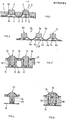
- the arrangement comprises a profiled mat 1, made of rubber-elastic material with key areas 2 and support areas 3.
- the mat 1 lies on a device-side support plate 4.
- the profiling of the mat results in key areas 2 which project coaxially with respect to an axis A perpendicular to the mat , which are connected to the support areas 3 with bridge pieces 5.
- This creates, assigned to each key area, a compressible cavity 6 by actuating the key area, in which, on the carrier plate 4, electrical contacts 7 are arranged in interaction with the contact areas 8 arranged on the key areas 2.
- the key areas 2 protruding in the form of a pin are further coaxial with the axis A. Movements, guided in a structure 9 of the carrier arrangement.
- the structure 9 is provided with a perforation pattern and placed over the mat 1 such that the key areas 2 protrude through the perforations 10. In this way it is ensured that the key areas 2 are movable in particular coaxially to the axis A.
- the cavities between the structure 9 and the mat 1 are susceptible to contamination and are difficult to clean.
- the arrangement here again consists of a mat 1a made of rubber-elastic material, with support areas 3a for resting on a carrier plate 4a and with key areas 2a for actuation.
- the support areas 3a and the button areas 2a are connected by bridge parts 5a in such a way that cavities 6a are formed between the button areas 2a and the carrier plate 4a. In it are on the key area 2a, and on the carrier plate 4a interacting contacts 7a, respectively. 8a provided.
- this first embodiment variant of the arrangement according to the invention does not have an actuation-side structure corresponding to 9 of FIG. 1, but the mat 1a is arranged directly on the carrier plate 4a.
- the mat 1a covers the support plate 4a in a sealing manner and is accessible in its entirety for cleaning from the outside.
- the mat 1a can further be replaced with little effort, since it can only be plugged onto the carrier plate 4a, for example by means of pins 9a. That the manufacturing effort and thus the cost of such an arrangement compared to that of Fig. 1 is cheaper. are taken for granted.
- the arrangement according to FIG. 2 has the advantage that when certain Contacts 7a provided on a standard carrier plate 4a are not required in the case of a device design, this can be taken into account in that the correspondingly assigned contact parts 2a are provided as passive contact areas, as shown in dashed lines at 5b.
- a disadvantage of this first arrangement variant is that, as shown in the left key area 2a, the degree of freedom of the key area operability is too great for some types of use, in that the key areas are not only actuated coaxially to the mat perpendicular A, but can also be tilted by correspondingly oblique pressure , which can lead to unsafe contact between the contact parts 7a and 8a.
- this possibility can be used in the arrangement according to the invention to selectively control several different switching functions with one key area by selective, lateral tilting.
- the key areas 11 are provided with guide pistons 12 protruding against the carrier plate 14, the latter carrying the one contact 13 of an electrical switch.
- the pistons 12 are guided axially in corresponding recesses in a guide structure 16 which also serves as a base for the mat 15.
- the mat 15 is attached to the guide structure by means of pins 18.
- the slide bearings 19 formed by the guide structure 16 and the pistons 12 have little play and, with a corresponding shape, as shown at 19, there is as little movement friction as possible between the key areas 11 and Management structure 16 ensured.
- cavities 17 in which the guide pistons 12 move via key areas 11 must not be sealed from one another, since otherwise a pressure build-up arises when they are actuated. Passages 20 between these cavities 17 prevent this. The same result is achieved if not all support areas are tightly attached to the structure, so that the entire mat structure can absorb the resulting excess pressures.
- the key areas 11 can have different shapes, particularly when viewed from above, and are usually labeled.
- a clamping edge sealingly projecting beyond the mat 15 can be provided on a housing 21, if necessary with a sealing profile (not shown) on the mat edge or on the clamping edge. In this way, the mat 15 and the housing-side parts form a tight unit.
- a piston-like continuation is again provided on the underside of a key area 23, but is not guided in a counter structure on its periphery, but in its axial center area.
- the piston area 23, which is elongated like a piston, is provided with a coaxially extending recess 24, into which a corresponding shape 25 projects on the carrier plate 14.
- the entire mat structure with the described guide pistons is in one piece here. If, for example, transparent silicone rubber is used as the mat material, as shown in FIG.
- the piston-like elongated key area 30 can be guided on the piston periphery and have a coaxial recess 32, in which an actuation-indicating signal lamp 34, such as a light-emitting diode, is arranged.
- an actuation-indicating signal lamp 34 such as a light-emitting diode
- knobs can also be provided for actuating membrane switches.
- the keyboard mats described are fixed on their support from below. Your key areas are on the inside, i.e. the device side, so that no housing cover is necessary and the arrangement thus forms a hermetically sealed unit from the outside without cracks with the housing.
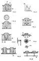
- FIG. 6 shows a further exemplary embodiment of such an arrangement. It has key areas 41, extended in a piston-like manner for its guidance, with contact pills 43 which act on conductor tracks 44 of a carrier plate 45 designed as a printed circuit. The mat is fixed by means of plug-in pills 48 which are inserted into corresponding recesses in the guide structure 51 on the housing side. The piston-like elongated key portions 41 are slidingly guided in corresponding openings 49 of the guide structure 51 and connecting openings 50 prevent, as has already been described, the generation of excess pressure in the button area - actuation.
- FIG. 7 An example of labeling of the key areas is shown in FIG. 7. To this as corresponding to a change to be modified data entry program at a loading dienun g skonsole, in the described arrangement with very little effort, the mat can be substituted.
- FIG. 8 shows a further exemplary embodiment of the arrangement according to the invention.
- a mat 53 likewise made of rubber-elastic material, is placed over the mat 52, as shown in FIG. 8, in its areas 54 corresponding to the key area is now labeled.
- the covering mat 53 is either simply placed on the switching active mat 52 as a pure labeling mat or can act as a labeling-specific switching mat, as shown in FIG. 8.
- the cover mat 53 has extensions 55 projecting downwards, with contacts 55a, cooperating with one or more conductor tracks on the carrier plate 14.
- cover mats 53 for example labeled differently for different uses, the extensions 55 are provided at different locations are, for short-circuiting different conductor tracks on the carrier plate 14, it is achieved that different program sequences are controlled accordingly by placing different cover mats 53, for example in the case of computer operating consoles. If desired, the cover mat 53, as shown in the edge areas, is also sealed with the actual switch mat underneath and the housing. A data processing system, for example, can be made with the cover mat-specific contacts 55a recognize which type of cover mat 53 has been placed. In the middle area, the covering mat 53 can additionally be held by latching knobs 57.
- the mat-specific fixed switches 55, 55a shown with reference to FIG. 8 can of course also be provided directly on interchangeable mats, such as 15 from FIG. 3.
- the cover mat 53 With a cover mat 53, as shown in FIG. 8, the resulting increase in the actuation pressure for the key areas must be taken into account.
- the cover mat 53 can be kept at a distance with respect to the actual switch mat 52, in particular in the bridge areas, forming cavities 58, but this is not absolutely necessary in accordance with the selected cover mat material and its dimensions.
- buttons 9 show a further exemplary embodiment of the arrangement according to the invention.
- a button-side contact 59 moves away from a printed circuit board 60, so that a contact interruption is triggered here by actuating the button area.
- a contact 61 which closes when the key area is actuated can be provided.
- FIG. 10 and 11 show further exemplary embodiments in which closing and interrupting contacts actuated by a key area are not actuated simultaneously but successively during the key area movement.
- a first normally closed contact 62 is opened immediately at the start of the key area actuation, after which a normally open contact 63 closes before finally another normally open contact 64 is closed.
- the bottom of the key area consists of several plastic or rubber parts which can be plugged in and exchanged, for example, as shown with the parts BCD in FIG. 10.
- FIG. 1 An example is shown in FIG. 1 1, in which first make contacts 67 are closed before normally closed contacts 66 open.
- a membrane profile 65 is prestressed such that the associated contact 66 does not open when the button area is actuated before the contact 67 has closed.
- Such arrangements of additional resilient contact parts with possibly different spring preload in the key area rest position can also serve to influence the course of the actuating force for the key areas.
- the membrane profile 65 of FIG. 11 can serve to reduce the necessary actuating force, the overhead profile 68 to increase the necessary force.
- the actuation characteristics of these key areas can be varied in a wide variety of ways. If the provision of such resilient organs, as already stated, is carried out selectively for certain key areas by plug-in assembly of individual such organs, it can also be achieved that certain key areas are more difficult to actuate than others. This may be desirable for operational safety.
- Contacts 70 arranged on the underside of the key area 69 are thereby separated by a conductive end 71 of the button area 69, e.g. made of conductive plastic, short-circuited.
- the arrangement of the contacts 70 is shown in a top view in FIG. 12. It can be seen from this that, depending on the direction of inclination of the stick-like button area 69, the conductive part 71 selectively short-circuits contacts 70.
- a guide template 72 can also be provided.
- FIG. Two or four switching positions with corresponding switching contacts 73 are provided on the carrier arrangement for each key area.
- a contact pill 73a e.g. made of conductive plastic
- the movement of the key area which is characteristic of this type of switching is also determined in part by the bridge part profiles 74. If only two switching movements are provided, the movement of the key area can also be specified with cams guided in scenes, as shown for example in FIG. 16.
- the key area shown in FIG. 13 is tilted into one switching position, in FIG. 15 into the other.
- FIG. 16 shows an exemplary embodiment in which the key area is tilted into one of the contact positions 76, similar to that shown in FIGS. 13 to 15.
- the pushing movement of cams 77 under locking hooks 78 locks the button, as shown in FIGS. 17 and 18, in the selected, tilted position.
- the lock is released again by the reverse sliding movement with light pressure on the button area.
- 19 and 20 show examples in which the interlocking cams or ribs 79 prevent the key areas from being pulled out of the rest position.
- cams 80 hold the key area in a position slightly below its actual rest position, so that the bridge profile 81 is already somewhat deformed and prestressed. In this way, the operating characteristics of the key area can be influenced.
- the shaping of the bridge profile 81 shown in FIG. 21 can, however, also be provided during the manufacture of the mat.
- the bridge areas connecting the key areas and support areas are designed as spring bridge mat areas, i.e. with the mat in one piece, designed and, viewed in the direction of the mat cross section, applied so that the actuating force in at least one component in the longitudinal direction of the bridge, i.e. upsetting, acts on it.
- the result is that the actuating force K first increases to actuate a key area until an actuating position S1 is reached, then passes through a maximum and then falls again.
- the switching-effective position is preferably provided immediately after passing through the maximum M, as shown in FIG. 22 at S s , or, as shown at S, in a minium following the maximum M.
- the direction of the actuating force is represented by K and, in the spring bridge mat section 81, in particular the component K 1 acting in the longitudinal direction of the bridge section. In the rubber-elastic mat material in particular, this component caused the increase in actuation force shown in FIG. 22 with subsequent passage of the maximum force M.
- the shape of the spring bridge Mat sections 81 have a significant influence on the displacement path / force curve. For example, the pretension according to FIG. 21 or the corresponding shape during mat production.
- FIG. 23 shows a square button area extension on the underside which runs in a round device-side guide cylinder, as was illustrated, for example, with reference to FIG. 3. This results in a small area of friction.
- Additional guide rings 85 as shown in the exemplary embodiment according to FIG. 24, make it possible to further reduce the play between the extension of the key area on the carrier arrangement side and guides on the carrier arrangement, thereby increasing the slidability.
- These guide rings 85 on the key area extension can have knob surfaces on their periphery or can also be angularly shaped in order to in turn form small friction surfaces on the guide cylinders.
- these rings additionally prevent a key area from being pulled out.
- a narrowing 86 in the key region extension on the carrier arrangement side results in a certain flexibility of bending of a contact part 88, so that this also adapts when the key region and / or the printed circuit board 89 carrying the counter contacts is inclined.
- the purpose of the arrangement according to FIG. 26 is to design the mat in such a way that only a very small installation depth is required.
- the key area is guided only by the mat itself.
- the contact area 90 on the key area is ring-shaped and made of soft material.
- Contact tracks 91 on the circuit board form contact stars or concentric circles.
- the current contact arrangement 91a on the printed circuit board would not allow a safe short circuit if the contact on the key area came into contact obliquely, depending on its position. Such a short-circuiting is ensured in any case with the star-shaped or ring-shaped conductor track arrangement.
- On the left is a basic enlargement of a part of the contact star, which shows how the rays interlock radially, separately and are connected to the external and internal power supply.
- the contact on the key area is pill-shaped.
- the ring shape of this contact 90 shown in FIG. 26 is significant because such a ring can be deformed much more easily in the inclined position than a pill. This deformation means that the ring adapts to the area of the underlying circuit board, that the contact area is increased and the desired short circuit is ensured.
- the flexibility of the contact ring 90 is further increased by the shape of the truncated cone of the button area underside 92 and the cavity 92a also provided there elevated.
- 27 and 28 show further exemplary embodiments.
- Known film switches form an electrical contact when an upper film is pressed onto a lower one.
- a knob 93 or a pin 94 with a small diameter on the underside of a button area of the mat is advantageous for the actuation of such membrane switches, since this results in a reduction in the necessary actuation force compared to a larger actuation area.
- 29 shows an exemplary embodiment of an optical switch in an optoelectric system.
- Under the button area are light emitters 95 and detectors 96, e.g. placed in a matrix, so that pressing a button area causes the beam to be interrupted in the W and / or Y axis.
- the key area extension can be provided with a cavity 97, so that this area is soft because the side wall bends around the cavity 97.
- a key area here consists of a rigid zone 100 and the flexible, more flexible spring bridge parts 101.
- Fig. 31 shows a sectional view through such a key area in the rest position, Fig. 32 in the actuated position.
- contacts the example showing a surface made of conductive silicone rubber 103 and contact tracks 104 on a printed circuit board.
- Another switching system can be used analogously.
- pins or protruding ribs 106 are drawn in, which serve to fix the mat on its support.
- the passage opening 107 serves to equalize the pressure when a key area is actuated.
- FIG. 33 shows the side view of a mat with key areas designed in accordance with FIGS. 30 to 32. It goes without saying that the surfaces of the key areas can be labeled.
- the key area 110 is supported on the carrier 114 with a relatively rigid tilting bearing section 112.
- the spring section 116 is tensioned by the button tipping over in the direction indicated so that the contact pill 118 closes the switching path underneath.
- the spring section 120 is compressed and, by means of a snap effect, generates feedback to the operator that the switch has been carried out correctly.
Landscapes
- Push-Button Switches (AREA)
Priority Applications (1)
| Application Number | Priority Date | Filing Date | Title |
|---|---|---|---|
| AT84103841T ATE51107T1 (de) | 1983-04-20 | 1984-04-06 | Tastaturanordnung. |
Applications Claiming Priority (6)
| Application Number | Priority Date | Filing Date | Title |
|---|---|---|---|
| CH2105/83 | 1983-04-20 | ||
| CH210583 | 1983-04-20 | ||
| CH552183 | 1983-10-11 | ||
| CH5521/83 | 1983-10-11 | ||
| CH6100/83 | 1983-11-14 | ||
| CH610083 | 1983-11-14 |
Publications (3)
| Publication Number | Publication Date |
|---|---|
| EP0123184A2 true EP0123184A2 (fr) | 1984-10-31 |
| EP0123184A3 EP0123184A3 (en) | 1986-10-01 |
| EP0123184B1 EP0123184B1 (fr) | 1990-03-14 |
Family
ID=27173451
Family Applications (1)
| Application Number | Title | Priority Date | Filing Date |
|---|---|---|---|
| EP84103841A Expired - Lifetime EP0123184B1 (fr) | 1983-04-20 | 1984-04-06 | Disposition de clavier |
Country Status (3)
| Country | Link |
|---|---|
| US (1) | US4536625A (fr) |
| EP (1) | EP0123184B1 (fr) |
| DE (1) | DE3481670D1 (fr) |
Cited By (15)
| Publication number | Priority date | Publication date | Assignee | Title |
|---|---|---|---|---|
| WO1985003595A1 (fr) * | 1984-02-03 | 1985-08-15 | Npm International | Ameliorations de commutateurs et de claviers |
| FR2602608A1 (fr) * | 1986-08-07 | 1988-02-12 | Campo Herve | Clavier avec plaque indexee amovible identifiant les fonctions des touches et les programmations a utiliser |
| EP0337045A1 (fr) * | 1988-04-12 | 1989-10-18 | Murakami Kaimeido Co., Ltd | Commutateur electrique multi-position |
| EP0313952A3 (en) * | 1987-10-26 | 1990-09-26 | Preh-Werke Gmbh & Co. Kg | Push-button for keyboard |
| FR2647588A1 (fr) * | 1989-05-23 | 1990-11-30 | Moulinex Sa | Clavier interrupteur pour tableau de commande d'un appareil electrique |
| EP0486388A1 (fr) * | 1990-11-16 | 1992-05-20 | Syrelec | Structure d'interrupteur utilisable pour la réalisation de claviers, et claviers utilisant une telle structure |
| WO1995015000A1 (fr) * | 1993-11-26 | 1995-06-01 | Bausch & Lomb Incorporated | Interrupteur manuel a positions multiples |
| GB2301794A (en) * | 1995-06-06 | 1996-12-18 | Nec Corp | Composite moulded product and method of manufacturing the same |
| EP0729163A3 (fr) * | 1995-02-24 | 1998-03-18 | Preh-Werke GmbH & Co. KG | Clavier pour caisses enregistreuses |
| DE19757515C1 (de) * | 1997-12-23 | 1999-06-17 | Kostal Leopold Gmbh & Co Kg | Mehrstufiger elektrischer Schalter |
| EP2261773A1 (fr) * | 2009-06-09 | 2010-12-15 | Research In Motion Limited | Boule de commande cliquable directionnellement |
| EP1430495B1 (fr) * | 2001-09-27 | 2011-11-16 | Phonak Ag | Commutateur electromecanique |
| DE10237719B4 (de) * | 2002-08-17 | 2011-12-15 | Robert Bosch Gmbh | Schaltvorrichtung mit einem Schaltelement sowie Verfahren zur Herstellung einer solchen Schaltvorrichtung |
| EP2732753A4 (fr) * | 2012-04-11 | 2015-09-30 | Olympus Medical Systems Corp | Couvercle d'interrupteur, dispositif d'interrupteur et endoscope |
| WO2022221888A1 (fr) | 2021-04-19 | 2022-10-27 | Drory Matthaeus | Dispositif d'entrée électronique |
Families Citing this family (54)
| Publication number | Priority date | Publication date | Assignee | Title |
|---|---|---|---|---|
| DE3615742A1 (de) * | 1986-05-09 | 1987-11-12 | Schoeller & Co Elektrotech | Folientastschalter |
| US4814566A (en) * | 1987-10-20 | 1989-03-21 | Sigl Edward D | Push-button keyboard assembly with EMI and RFI-shielded multiple individually-replaceable switch modules |
| GB8800370D0 (en) * | 1988-01-08 | 1988-02-10 | Marconi Electronic Devices | Push-button keyswitches |
| JP2694913B2 (ja) * | 1990-02-21 | 1997-12-24 | シャープ株式会社 | スイッチ装置 |
| US5153590A (en) * | 1991-02-04 | 1992-10-06 | Motorola, Inc. | Keypad apparatus |
| US5311656A (en) * | 1991-03-12 | 1994-05-17 | Mitel Corporation | Keypad method of manufacture |
| CA2090001A1 (fr) * | 1992-02-22 | 1993-08-23 | William W. Kidston | Interrupteurs de bouchon de touche |
| US5163765A (en) * | 1992-03-04 | 1992-11-17 | Apple Computer, Inc. | Collapsible keyboard |
| EP0565959B1 (fr) * | 1992-04-14 | 1996-08-28 | MOTOROLA GmbH | Clavier |
| US5412169A (en) * | 1992-05-12 | 1995-05-02 | Molex Incorporated | Rocker switch with improved rocker actuator |
| US5475192A (en) * | 1993-03-15 | 1995-12-12 | Teikoku Tsushin Kogyo Co., Ltd. | Keytop sheet for push-button switches |
| EP0685860A1 (fr) * | 1994-06-03 | 1995-12-06 | Hewlett-Packard Company | Clavier à grand déplacement, étanche et éclairé par l'arrière |
| US5508479A (en) * | 1994-11-17 | 1996-04-16 | Schooley; John L. | Elastomeric rocker switch assembly |
| DE19505852C1 (de) * | 1995-02-21 | 1996-05-15 | Preh Elektro Feinmechanik | Tastenfeld mit Schutzfolie |
| US5681515A (en) * | 1996-04-12 | 1997-10-28 | Motorola, Inc. | Method of fabricating an elastomeric keypad |
| US5739486A (en) * | 1996-08-07 | 1998-04-14 | Ford Motor Company | Push-button system for control panels |
| US5783787A (en) * | 1996-11-12 | 1998-07-21 | Molex Incorporated | Electrical switch assembly |
| DE19718677A1 (de) * | 1997-05-02 | 1998-11-05 | Kontron Elektronik | Tastenfeld für wasserdichte und schmutzunempfindliche Computer-Tastaturen |
| DE29716198U1 (de) * | 1997-09-09 | 1997-10-30 | Gira Giersiepen Gmbh & Co Kg, 42477 Radevormwald | Elektrisches Installationsgerät, insbesondere Taster, Seller oder Schalter |
| WO1999017180A1 (fr) * | 1997-09-29 | 1999-04-08 | Varatouch Technology Incorporated | Dispositif de pointage a commutateur integre |
| US6184866B1 (en) | 1997-09-29 | 2001-02-06 | Varatouch Technology Incorporated | Pointing device |
| GB2336457A (en) * | 1998-04-14 | 1999-10-20 | Ford Motor Co | Button carrier and display backlight |
| GB2346739B (en) | 1999-02-12 | 2002-12-18 | Nokia Mobile Phones Ltd | Keypad structure |
| DE19957643A1 (de) * | 1999-11-30 | 2001-05-31 | Ticona Gmbh | Entkoppelte Drucktasten |
| GB2367346B (en) * | 2000-09-28 | 2004-07-14 | Nokia Mobile Phones Ltd | Control device |
| DE10140337B4 (de) * | 2001-08-16 | 2005-02-24 | Siemens Ag | Elektronisches Endgerät |
| AU2001289460A1 (en) * | 2001-09-27 | 2002-01-21 | Phonak Ag | Electromechanical switch |
| US7355590B2 (en) * | 2002-04-30 | 2008-04-08 | Nokia Corporation | Keymat |
| JP4147839B2 (ja) * | 2002-06-26 | 2008-09-10 | ポリマテック株式会社 | スライド式多方向入力キー |
| US20040222979A1 (en) * | 2003-05-08 | 2004-11-11 | Knighton Mark S. | Multifunction floating button |
| US8734036B2 (en) * | 2003-08-29 | 2014-05-27 | Steven B. Hirsch | Keyboard and keys |
| US20100040400A1 (en) * | 2003-08-29 | 2010-02-18 | Hirsch Steven B | Keyboard and keys |
| US7131780B2 (en) * | 2003-08-29 | 2006-11-07 | Hirsch Steven B | Keyboard |
| US7087847B2 (en) * | 2003-11-20 | 2006-08-08 | White Electronic Designs Corporation | Elastomer keypad and bezel |
| US7030329B1 (en) * | 2004-10-22 | 2006-04-18 | Solectron Invotronics | Switch contact |
| US6982392B1 (en) * | 2005-05-06 | 2006-01-03 | Burger & Brown Engineering, Inc. | Water resistant actuating mechanism for plunger type switches |
| US7855715B1 (en) * | 2005-07-27 | 2010-12-21 | James Harrison Bowen | Switch with depth and lateral articulation detection using optical beam |
| TWI316261B (en) * | 2006-08-02 | 2009-10-21 | Darfon Electronics Corp | Keyboard structure |
| US7823780B2 (en) * | 2006-12-18 | 2010-11-02 | Harrow Products Llc | Data interface assembly for electronic locks and readers |
| US7982149B2 (en) * | 2008-09-29 | 2011-07-19 | Microsoft Corporation | Mechanical architecture for display keyboard keys |
| US20100214135A1 (en) * | 2009-02-26 | 2010-08-26 | Microsoft Corporation | Dynamic rear-projected user interface |
| US20100309129A1 (en) * | 2009-06-09 | 2010-12-09 | Research In Motion Limited | Directional clickable trackball |
| US8183478B2 (en) * | 2009-10-26 | 2012-05-22 | Research In Motion Limited | Key assembly for an electronic device having a connected keycap |
| TWM413205U (en) * | 2011-03-08 | 2011-10-01 | Weistech Technology Co Ltd | Portable appliance key module structure |
| DE102010024900B3 (de) * | 2010-06-24 | 2011-05-26 | Sick Ag | Verfahren zur Herstellung eines optoelektronischen Sensors mit einem Bedienelement und optoelektronischer Sensor mit einem Bedienelement |
| US8284079B2 (en) * | 2010-08-31 | 2012-10-09 | Giga-Byte Technology Co., Ltd. | Keyboard module |
| US8647203B2 (en) * | 2011-11-04 | 2014-02-11 | Target Brands, Inc. | Transaction product with selectively illuminated buttons |
| US8896539B2 (en) | 2012-02-03 | 2014-11-25 | Synerdyne Corporation | Touch-type keyboard with character selection through finger location on multifunction keys |
| US8414207B1 (en) | 2012-02-03 | 2013-04-09 | Synerdyne Corporation | Ultra-compact mobile touch-type keyboard |
| US8686948B2 (en) | 2012-02-03 | 2014-04-01 | Synerdyne Corporation | Highly mobile keyboard in separable components |
| US8629362B1 (en) | 2012-07-11 | 2014-01-14 | Synerdyne Corporation | Keyswitch using magnetic force |
| US9235270B2 (en) | 2013-02-26 | 2016-01-12 | Synerdyne Corporation | Multi-touch mechanical-capacitive hybrid keyboard |
| JP5933859B2 (ja) * | 2014-04-22 | 2016-06-15 | オリンパス株式会社 | 内視鏡用操作部及び内視鏡 |
| WO2017184107A1 (fr) * | 2016-04-18 | 2017-10-26 | Gyrus Acmi Inc., D.B.A. Olympus Surgical Technologies America | Mécanisme de commutation électronique |
Family Cites Families (22)
| Publication number | Priority date | Publication date | Assignee | Title |
|---|---|---|---|---|
| GB1259356A (fr) * | 1969-04-16 | 1972-01-05 | ||
| US3728509A (en) * | 1970-09-26 | 1973-04-17 | Alps Electric Co Ltd | Push-button switch with resilient conductive contact member with downwardly projecting ridges |
| US3760137A (en) * | 1970-10-05 | 1973-09-18 | Alps Electric Co Ltd | Matrix push-button switch |
| FR2196515B1 (fr) * | 1972-08-18 | 1977-09-16 | Matsushita Electric Industrial Co Ltd | |
| US3932722A (en) * | 1974-04-16 | 1976-01-13 | Nippo Communication Industrial Co., Ltd. | Push button body for a push-button switch providing snap-action of the switch |
| JPS5329226B2 (fr) * | 1973-08-23 | 1978-08-19 | ||
| US3930083A (en) * | 1974-07-26 | 1975-12-30 | Litton Systems Inc | Keyboard panel for an electric switch contact |
| DE2540011C3 (de) * | 1974-09-09 | 1979-08-23 | Sharp K.K., Osaka (Japan) | Elektronischer Rechner |
| US4066860A (en) * | 1974-09-26 | 1978-01-03 | Sharp Kabushiki Kaisha | Pushbutton switch key arrangement for keyboards having indicia |
| US4109118A (en) * | 1976-09-01 | 1978-08-22 | Victor Kley | Keyswitch pad |
| US4127758A (en) * | 1977-10-13 | 1978-11-28 | Sheldahl, Inc. | Tactile layer having hinged dome |
| JPS54101176A (en) * | 1978-01-26 | 1979-08-09 | Shinetsu Polymer Co | Contact member for push switch |
| US4216968A (en) * | 1978-10-11 | 1980-08-12 | David Yeeda | Self-scoring multiple function dart game |
| JPS5577331U (fr) * | 1978-11-24 | 1980-05-28 | ||
| FR2442502A1 (fr) * | 1978-11-24 | 1980-06-20 | Orega Cifte | Clavier a touches a effet tactile de declenchement brusque |
| JPS5624718A (en) * | 1979-08-06 | 1981-03-09 | Shinetsu Polymer Co | Pushhbutton switch |
| JPS5850606Y2 (ja) * | 1979-08-24 | 1983-11-17 | 日産自動車株式会社 | ヒュ−ズの断線検査装置 |
| US4376238A (en) * | 1980-03-12 | 1983-03-08 | International Computers Limited | Electrical devices |
| DE3025024C2 (de) * | 1980-07-02 | 1982-04-29 | Schoeller & Co Elektrotechnische Fabrik Gmbh & Co, 6000 Frankfurt | Folienschalter |
| DE3041859A1 (de) * | 1980-11-06 | 1982-06-03 | Preh Elektro Feinmechanik | Tastatur |
| DE3044414A1 (de) * | 1980-11-26 | 1982-06-24 | Licentia Gmbh | Elektrische schalteranordnung |
| US4408103A (en) * | 1982-01-06 | 1983-10-04 | Smith Engineering | Joystick operated multiple position switch |
-
1984
- 1984-04-06 EP EP84103841A patent/EP0123184B1/fr not_active Expired - Lifetime
- 1984-04-06 DE DE8484103841T patent/DE3481670D1/de not_active Expired - Fee Related
- 1984-04-13 US US06/599,801 patent/US4536625A/en not_active Expired - Fee Related
Cited By (21)
| Publication number | Priority date | Publication date | Assignee | Title |
|---|---|---|---|---|
| US4839474A (en) * | 1984-02-03 | 1989-06-13 | Key Innovations Limited | Switches and keyboards |
| WO1985003595A1 (fr) * | 1984-02-03 | 1985-08-15 | Npm International | Ameliorations de commutateurs et de claviers |
| FR2602608A1 (fr) * | 1986-08-07 | 1988-02-12 | Campo Herve | Clavier avec plaque indexee amovible identifiant les fonctions des touches et les programmations a utiliser |
| EP0313952A3 (en) * | 1987-10-26 | 1990-09-26 | Preh-Werke Gmbh & Co. Kg | Push-button for keyboard |
| EP0337045A1 (fr) * | 1988-04-12 | 1989-10-18 | Murakami Kaimeido Co., Ltd | Commutateur electrique multi-position |
| FR2647588A1 (fr) * | 1989-05-23 | 1990-11-30 | Moulinex Sa | Clavier interrupteur pour tableau de commande d'un appareil electrique |
| EP0486388A1 (fr) * | 1990-11-16 | 1992-05-20 | Syrelec | Structure d'interrupteur utilisable pour la réalisation de claviers, et claviers utilisant une telle structure |
| FR2669462A1 (fr) * | 1990-11-16 | 1992-05-22 | Syrelec | Structure d'interrupteur utilisable pour la realisation de claviers, et claviers utilisant une telle structure. |
| WO1995015000A1 (fr) * | 1993-11-26 | 1995-06-01 | Bausch & Lomb Incorporated | Interrupteur manuel a positions multiples |
| US5516991A (en) * | 1993-11-26 | 1996-05-14 | Bausch & Lomb Incorporated | Multiple position manual switch |
| EP0729163A3 (fr) * | 1995-02-24 | 1998-03-18 | Preh-Werke GmbH & Co. KG | Clavier pour caisses enregistreuses |
| GB2301794A (en) * | 1995-06-06 | 1996-12-18 | Nec Corp | Composite moulded product and method of manufacturing the same |
| GB2301794B (en) * | 1995-06-06 | 1998-04-08 | Nec Corp | Composite molded product and method of manufacturing the same |
| US5779230A (en) * | 1995-06-06 | 1998-07-14 | Nec Corporation | Method of making a composite button of an electrical device |
| US6238771B1 (en) | 1995-06-06 | 2001-05-29 | Nec Corporation | Composite molded product for use as a button for electric devices and method of manufacturing the same |
| DE19757515C1 (de) * | 1997-12-23 | 1999-06-17 | Kostal Leopold Gmbh & Co Kg | Mehrstufiger elektrischer Schalter |
| EP1430495B1 (fr) * | 2001-09-27 | 2011-11-16 | Phonak Ag | Commutateur electromecanique |
| DE10237719B4 (de) * | 2002-08-17 | 2011-12-15 | Robert Bosch Gmbh | Schaltvorrichtung mit einem Schaltelement sowie Verfahren zur Herstellung einer solchen Schaltvorrichtung |
| EP2261773A1 (fr) * | 2009-06-09 | 2010-12-15 | Research In Motion Limited | Boule de commande cliquable directionnellement |
| EP2732753A4 (fr) * | 2012-04-11 | 2015-09-30 | Olympus Medical Systems Corp | Couvercle d'interrupteur, dispositif d'interrupteur et endoscope |
| WO2022221888A1 (fr) | 2021-04-19 | 2022-10-27 | Drory Matthaeus | Dispositif d'entrée électronique |
Also Published As
| Publication number | Publication date |
|---|---|
| EP0123184A3 (en) | 1986-10-01 |
| DE3481670D1 (de) | 1990-04-19 |
| EP0123184B1 (fr) | 1990-03-14 |
| US4536625A (en) | 1985-08-20 |
Similar Documents
| Publication | Publication Date | Title |
|---|---|---|
| EP0123184B1 (fr) | Disposition de clavier | |
| DE19924012B4 (de) | In mehreren Richtungen wirksame Eingabevorrichtung | |
| DE602004010763T2 (de) | Steuerknüppeleingabegerät | |
| EP0740844B1 (fr) | Interrupteur a plusieurs etages | |
| DE19853438A1 (de) | Multidirektionale Tastschalteranordnung | |
| EP0876940A2 (fr) | Interrupteur multifonction à bouton poussoir | |
| DE19829811C2 (de) | Mehrrichtungs-Eingabevorrichtung | |
| DE2515185C3 (de) | Elektrischer Schnappschalter | |
| DE4443726C2 (de) | Mehrrichtungs-Eingabeschalter | |
| DE4139554A1 (de) | Elektrischer tastschalter | |
| DE3533719A1 (de) | Schalteranordnung mit einer mehrzahl von bedienelementen | |
| DE3129210C2 (de) | Elektrische Schaltvorrichtung | |
| EP1537589B1 (fr) | Commutateur a touche de commande a bascule | |
| EP0678885B1 (fr) | Touche électrique | |
| WO2012168326A1 (fr) | Unité de commande pour un composant de véhicule | |
| DE19836793C2 (de) | Bedienelement zum selektiven Herstellen elektrischer Kontakte | |
| DE4221458A1 (de) | Schalteinrichtung | |
| DE9110485U1 (de) | Klapptastenanordnung für einen Tippschalter | |
| WO2003017300A2 (fr) | Appareil terminal electronique | |
| DE19526951C2 (de) | Schaltvorrichtung für ein Automatikgetriebe | |
| EP1482527A1 (fr) | Interrupteur à bouton poussoir | |
| DE3111407A1 (de) | Tastenschalter | |
| EP4164911B1 (fr) | Unité de commande pour un véhicule | |
| EP0593077B1 (fr) | Interrupteur d'appareil | |
| DE4036047A1 (de) | Staubsauger mit einer drucktastenschalteinrichtung |
Legal Events
| Date | Code | Title | Description |
|---|---|---|---|
| PUAI | Public reference made under article 153(3) epc to a published international application that has entered the european phase |
Free format text: ORIGINAL CODE: 0009012 |
|
| AK | Designated contracting states |
Designated state(s): AT BE CH DE FR GB IT LI LU NL SE |
|
| 17P | Request for examination filed |
Effective date: 19850419 |
|
| PUAL | Search report despatched |
Free format text: ORIGINAL CODE: 0009013 |
|
| AK | Designated contracting states |
Kind code of ref document: A3 Designated state(s): AT BE CH DE FR GB IT LI LU NL SE |
|
| 17Q | First examination report despatched |
Effective date: 19870317 |
|
| GRAA | (expected) grant |
Free format text: ORIGINAL CODE: 0009210 |
|
| AK | Designated contracting states |
Kind code of ref document: B1 Designated state(s): AT BE CH DE FR GB IT LI LU NL SE |
|
| PG25 | Lapsed in a contracting state [announced via postgrant information from national office to epo] |
Ref country code: SE Effective date: 19900314 Ref country code: NL Effective date: 19900314 Ref country code: IT Free format text: LAPSE BECAUSE OF FAILURE TO SUBMIT A TRANSLATION OF THE DESCRIPTION OR TO PAY THE FEE WITHIN THE PRESCRIBED TIME-LIMIT;WARNING: LAPSES OF ITALIAN PATENTS WITH EFFECTIVE DATE BEFORE 2007 MAY HAVE OCCURRED AT ANY TIME BEFORE 2007. THE CORRECT EFFECTIVE DATE MAY BE DIFFERENT FROM THE ONE RECORDED. Effective date: 19900314 Ref country code: GB Effective date: 19900314 Ref country code: FR Effective date: 19900314 Ref country code: BE Effective date: 19900314 |
|
| REF | Corresponds to: |
Ref document number: 51107 Country of ref document: AT Date of ref document: 19900315 Kind code of ref document: T |
|
| REF | Corresponds to: |
Ref document number: 3481670 Country of ref document: DE Date of ref document: 19900419 |
|
| PG25 | Lapsed in a contracting state [announced via postgrant information from national office to epo] |
Ref country code: LU Free format text: LAPSE BECAUSE OF NON-PAYMENT OF DUE FEES Effective date: 19900430 |
|
| EN | Fr: translation not filed | ||
| NLV1 | Nl: lapsed or annulled due to failure to fulfill the requirements of art. 29p and 29m of the patents act | ||
| GBV | Gb: ep patent (uk) treated as always having been void in accordance with gb section 77(7)/1977 [no translation filed] | ||
| PLBE | No opposition filed within time limit |
Free format text: ORIGINAL CODE: 0009261 |
|
| STAA | Information on the status of an ep patent application or granted ep patent |
Free format text: STATUS: NO OPPOSITION FILED WITHIN TIME LIMIT |
|
| 26N | No opposition filed | ||
| PGFP | Annual fee paid to national office [announced via postgrant information from national office to epo] |
Ref country code: AT Payment date: 19910426 Year of fee payment: 8 |
|
| PG25 | Lapsed in a contracting state [announced via postgrant information from national office to epo] |
Ref country code: AT Effective date: 19920406 |
|
| PGFP | Annual fee paid to national office [announced via postgrant information from national office to epo] |
Ref country code: DE Payment date: 19920625 Year of fee payment: 9 |
|
| PG25 | Lapsed in a contracting state [announced via postgrant information from national office to epo] |
Ref country code: DE Effective date: 19940101 |
|
| PGFP | Annual fee paid to national office [announced via postgrant information from national office to epo] |
Ref country code: CH Payment date: 19940624 Year of fee payment: 11 |
|
| PG25 | Lapsed in a contracting state [announced via postgrant information from national office to epo] |
Ref country code: LI Effective date: 19950430 Ref country code: CH Effective date: 19950430 |
|
| REG | Reference to a national code |
Ref country code: CH Ref legal event code: PL |