EP0123460A2 - Clinomètre de précision - Google Patents
Clinomètre de précision Download PDFInfo
- Publication number
- EP0123460A2 EP0123460A2 EP84302258A EP84302258A EP0123460A2 EP 0123460 A2 EP0123460 A2 EP 0123460A2 EP 84302258 A EP84302258 A EP 84302258A EP 84302258 A EP84302258 A EP 84302258A EP 0123460 A2 EP0123460 A2 EP 0123460A2
- Authority
- EP
- European Patent Office
- Prior art keywords
- sensor
- inclinometer
- signal
- responsive
- output
- Prior art date
- Legal status (The legal status is an assumption and is not a legal conclusion. Google has not performed a legal analysis and makes no representation as to the accuracy of the status listed.)
- Withdrawn
Links
Images


Classifications
-
- G—PHYSICS
- G01—MEASURING; TESTING
- G01C—MEASURING DISTANCES, LEVELS OR BEARINGS; SURVEYING; NAVIGATION; GYROSCOPIC INSTRUMENTS; PHOTOGRAMMETRY OR VIDEOGRAMMETRY
- G01C9/00—Measuring inclination, e.g. by clinometers, by levels
- G01C9/02—Details
- G01C9/06—Electric or photoelectric indication or reading means
Definitions
- the invention relates to leveling apparatus, and more particularly to a leveling device for displaying to a high degree of precision a numerical readout of the deviation from the horizontal or vertical.
- Leveling devices are known in the prior art where the sensing element is a conventional arcuate bubble level.
- the bubble level comprises a glass vial partially filled with a liquid and having an air gap therein whose position responds to the inclination of the level.
- One specific application is the common use as a carpenter's level where such a vial is embedded in a linear member which provides the reference plane and is aligned with the surface to be leveled.
- Another such device uses a bubble level hooked to a string stretched between two points to establish a level or grade.
- a hand-held sight glass has also been used in combination with a calibrated bubble level for quick field observations.
- graduations may be etched thereon to define the deviation from horizontal or vertical surfaces to which the level is applied.
- an inclinometer providing a numerical readout, characterised in that it comprises a housing having at least one reference surface power supply means for energising the inclinometer, sensor means mounted in the housing and responsive to the influence of terrestrial gravitational force and disposed for gravity responsive output as a function of orientation of the reference surface relative to the horizontal, signal means coupled to the sensor for energising the sensor to provide the gravity responsive output, detector means responsive to the output, for providing a signal when the sensor is inclined with respect to the horizontal, and numerical indicator means coupled to the detector means for providing a numerical output proportional to the sensed inclination.
- the inclinometer utilises as a sensor a bubble level of the electrolytic type, partially filled with a suitable conductive liquid and provided with electrical contacts.
- a pulse signal is differentially coupled to the sensor to energise the device.
- the output of the sensor is digitised and used to drive a digital display device, such as a liquid crystal display.
- Circuitry for stabilising the signal applied to the sensor provides a readout which is essentially linear and independent of power supply variations with time and temperature over a wide range.
- circuitry and components are selected to provide high stability with minimal power dissipation, thus assuring long life in the field when powered by a battery.
- the perspective view of the conceptual design of the inclinometer shows a housing 10 having a pair of parallel faces 11 and 11' adapted for measuring the tilt of essentially horizontal surfaces, and a second pair of parallel faces 12 and 12' at right angles to the faces 11 and 11', adapted for measuring essentially vertical surfaces.
- a numerical readout 13 provides a digital display of slope to four significant figures, although other displays of more or less digits may be used.
- the display provides a range of approximately + 10°, or more precisely, 9.45° of inclination corresponding to 1.999 inches per foot (16.5 cms per metre). This represents the essentially linear range of the sensing element.
- decimal digits of the display are automatically blanked to alert the observer that the linear range has been exceeded.
- Angular units such as degree-minutes of arc or microradians may also be displayed with suitable calibration of the circuitry.
- LCD liquid crystal display
- other displays such as light emitting diodes or even an expanded scale analogue meter may be used, by appropriately adapting the drive circuitry, at the expense of increased current consumption.
- a power switch 14 is provided, the device includes circuitry to minimise current consumption.
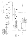
- FIG. 2 shows a block diagram of the preferred embodiment of the invention.
- a battery not shown, preferably a nine volt miniature type, energises a power supply 20.
- the power supply 20 provides balanced outputs +DC and -DC of equal and opposing polarities with respect to ground, derived from the battery (+4.5 and -4.5 for a nine-volt battery).
- An oscillator 21 provides a square wave at approximately 9.0 volts peak-to-peak and 400 Hz which drives a modulator 23.
- a precision voltage reference 24 provides a regulated voltage derived from the power supply 20 which is "chopped" by the modulator 23 in accordance with the driving pulse.
- This provides a 400 Hz pulse of essentially constant peak amplitude to an amplifier 25 which drives an invertor 26 and a sensor 27, thereby providing energisation of opposing phases relative to ground to contact electrodes a and b of the sensor 27.
- a common electrode c is coupled to an amplifier 29.
- a differential signal is developed across the contacts a-c and b-c, the amplitude and phase of which are determined by the tilt angle.
- the resultant signal at contact c is applied to an amplifier 29 which drives a demodulator 30, synchronized with the drive to the modulator 23 by the oscillator 21, to provide a rectified dc pulse output.
- the analogue output feeds an analogue-to-digital converter 32 and the digital outputs are used to drive a display driver 33, also housed on the same integrated circuit as the converter 32, via a multiple line bus 34 to energise an LCD display 35 and provide a readout in accordance with the magnitude and direction of inclination of the sensor 27.
- Blocks 36 and 37 comprise a battery voltage monitor and driver, respectively, for energising a low battery condition indicator on the LCD display when the battery voltage drops below a predetermined value, preferably of the order of seven volts for a nine volt battery.
- a pulse signal from the display driver 33 drives a decimal gate 38 continuously to energise the decimal point in the LCD display.
- a power supply 40 is energised by a dc battery 41, which may be a nine volt battery of the type commonly used in portable radios.
- Current from the battery 41 after passing through a power control switch 14, is applied to a divider network R l ,R 2 which is preferably comprised of equal resistors of relatively high value to minimise battery drain.
- An amplifier U 1 is comprised of one section of a quad linear operational amplifier integrated circuit which also includes U 2 -U 4 , to be described below.
- the junction of resistors R 1 and R 2 is applied to the positive input of the amplifier U 1 .
- the negative input of the amplifier U 1 and the output of the amplifier form the ground reference for the electronic circuitry.
- the symmetrical resistive network develops a midpoint voltage of 4.5 vdc at the positive input of the amplifier U I which is wired as a voltage follower, with the output voltage tracking the positive input voltage and unity gain. Under balanced conditions, no current flows through the ground return, and therefore the amplifier U 1 is not called upon to deliver any power. If there is an imbalance in the current demands between the positive or negative legs and ground, the amplifier U 1 will supply the difference current, thus rebalancing the output voltages without drawing additional current through R 1 or R 2 .
- This circuit thereby provides a very efficient means of providing positive and negative voltages of equal value from a common supply providing a low source impedance which would otherwise require relatively low values of R 1 and R 2 with consequential heavy drain on the battery, or an active regulator which has associated power losses.
- Capacitors C 1 and C 2 also preferably of equal value, provide additional storage capacity for smoothing the power supply output with respect to varying current demands.
- Figure 3 also shows the drive circuitry 50 for the electrolytic sensor 27.
- the oscillator 21 provides a 9.0 volt peak-to-peak 400 Hz square wave to an FET transistor modulator Q l and a resistor R 3 drops the positive power supply voltage, which is of the order of 4.5 volts dc, to 2.5 volts dc.
- a Zener diode D 1 must be of the type that has suitable temperature compensation to assure accurate operation of the inclinometer over a wide temperature range. Preferably, it should be suitable for use in the range of 32°F to 110°F, such as type LM 236 as manufactured by National Semiconductor Corporation, Santa Clara, California, U.S.A.
- the regulated voltage from R 3 is applied through a load resistor R 4 to the modulator Q 1 which is driven by the oscillator 21 to provide a precisely regulated pulsed output of 2.5 volts peak-to-peak to the capacitor C 3 and resistor R 5 , the former providing dc isolation, transmitting only the ac component of the input square wave.
- the ac voltage from the capacitor C 3 is then applied to the amplifier U 2 which buffers the signal to develop a low impedance 2.5 v peak-to-peak voltage for energising contact a of the sensor 27.
- the amplifier U 2 also drives invertor U 3 which provides a signal of equal amplitude and opposite phase to contact b of the sensor 27.
- Resistors R 5 , R 6 , R 7 and R 8 are used to establish input impedance and gain optimisation.
- Resistors R 9 and R13 are used to supply an ac offset bias to the amplifier U 4 to correct for irregularities in the mounting of the electrolytic sensor 27 which would adversely affect the accuracy of the null response at zero inclination.
- a signal is applied to the sensor 27 at contacts a and b.
- the sensor 27 may be an electrolytic level, such as type CG-57S with MKI electrolyte, as manufactured by SPECTRON Glass and Electronics Inc., Uniondale, New York, U.S.A.
- the electrolyte is specially compounded to provide low viscosity and relatively high resistivity for this application.
- the electrolyte contained therein provides paths of equal resistance between electrodes a-c and b-c. Since the voltages applied to a and b are opposite in phase, they sum to zero and provide no output at c with respect to ground.
- a differential voltage is developed between electrode c and ground, due to the differing resistive paths of the electrolyte, thereby applying a.c. drive to the amplifier U 4 .
- the output from the common electrode c of the level sensor 27 is developed across a resistor R 10 and thereupon coupled to the amplifier U 4 through a series capacitor C 6 and a resistor R 11 .
- Dc blocking capacitors C 4 , C 5 , and C 6 serve to prevent any flow of dc current from U 2 , U 3 , or U 4 back to the electrolytic sensor 27 which could lead to damage of the sensor by precipitation of ions in the electrolyte, or by generating gases which could change the bubble size.
- R 11 serves to scale the input voltage to the negative input of the amplifier U 4 .
- the positive input of the amplifier U 4 is referred to ground through a resistor R12 and a resistor R13 in combination with the bias voltage from R 9 applies an ac offset to the negative terminal of the amplifier U 4 .
- Resistor R14 determines the gain of the amplifier U 4 which amplifies the variable sensor output and feeds it to a capacitor C 7 which removes any dc offset voltage from the amplifier U 4 .
- the drive voltage is applied across a resistor R 15 to the FET transistor modulator Q 2 which is gated through the resistor R 16 by the oscillator 21 in synchronism with Q 1 , which is gated through R17, thereby demodulating and providing a rectified half-wave square-wave.
- a resistor R 18 and a capacitor C 8 filter the output of the modulator Q 2 to obtain a smooth dc output voltage proportional to the sensor tilt angle, and of positive or negative polarity, depending on the direction of tilt.
- the filtered dc output is then coupled to the analogue-to-digital converter 32.
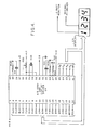
- an integrated circuit chip U 5 provides circuitry for A/D conversion and for driving the LCD display 35.
- An analogue input from the modulated Q 2 (see Figure 3) is applied to a pin 31 of U 5 .
- the A/D section of the chip U s digitises the analogue signal and provides a corresponding binary coded decimal number at any instant of time.
- the display driver section converts the binary information into suitable 7-bit output code for driving a seven segment digital display.
- the INTERSIL 7126 A/D converter circuit contains provisions for automatic blanking of the three decimal digits of the display when the reading exceeds 1.999 or -1.999, respectively.
- the inclinometer uses this characterisitic to advantage to prevent the user from acquiring inaccurate readings due to circuit or sensor saturation.
- the sensor range, circuit scaling, and decimal point placement are selected such that display blanking occurs just within the linear range of the sensor and the electronic circuitry. It wll be clear to one skilled in the art that while individual component tolerances are not generally critical, judicious balancing and selection of inclinometer components permits use of the important blanking feature of the circuit while providing a sensor with adequate range.
- the low battery monitor is comprised of Zener diode D 2 , a diode D 3 , a transistor Q 3 , and associated resistors.
- the operation of the low battery monitor is as follows.
- the diode D 2 which is selected to conduct at 6.2 to 6.8 vdc, will be biased into conduction through resistors R 30 and R31. This will provide forward bias to the collector-to-base junction of the transistor Q 3* Since the emitter-to-base junction is reversed biased by the negative supply and the drop across R 31 , the transistor Q 3 will be turned on.
- This output is the five-volt back plane pulse, and since there is no difference in potential between the back plane pulse and the voltage applied to the low battery terminal of the LCD, the "low battery” indicator will not be displayed.
- the diode D 2 In the condition where the primary battery source is low, which is preferably established at less than seven volts, the diode D 2 will be in a non-conducting state. The base to collector circuit will be open, and the transistor Q 3 will therefore be non-conducting, which allows the positive battery voltage to be transferred via R 32 and D 3 to one input of V 6 .
- the decimal point display operates on a similar concept.
- a constant positive 4.5 vdc is applied to one input of Exclusive-OR gate V 7-
- the back plane pulse is applied to the second input of V 7 and the back plane voltage is thereupon inverted in the gate to provide a 4.0 v output pulse whenever the back plane pulse is at zero, thus providing a continuous display of the decimal point whenever power is applied to the system.
- potentiometers R 9 and R 22 are used for null adjustment and scale factor adjustment, respectively.
- R 9 sums a portion of the sensor excitation voltages with the sensor output voltage either to add or to subtract in the level position, thereby to provide a fine adjustment of zero without the need for mechanically trimming the sensor mounting.
- R 22 trims the reference voltage to the A/D converter U s to adjust the gain or scale factor relating the inclination to the calibrated LCD display output.
Landscapes
- Physics & Mathematics (AREA)
- Engineering & Computer Science (AREA)
- General Physics & Mathematics (AREA)
- Radar, Positioning & Navigation (AREA)
- Remote Sensing (AREA)
- Transmission And Conversion Of Sensor Element Output (AREA)
- Measurement Of Current Or Voltage (AREA)
- Investigating Or Analyzing Materials By The Use Of Electric Means (AREA)
- Bridges Or Land Bridges (AREA)
- Liquid Crystal Display Device Control (AREA)
Applications Claiming Priority (2)
| Application Number | Priority Date | Filing Date | Title |
|---|---|---|---|
| US486631 | 1983-04-20 | ||
| US06/486,631 US4503622A (en) | 1983-04-20 | 1983-04-20 | Precision inclinometer with digital numerical readout |
Publications (2)
| Publication Number | Publication Date |
|---|---|
| EP0123460A2 true EP0123460A2 (fr) | 1984-10-31 |
| EP0123460A3 EP0123460A3 (fr) | 1986-09-17 |
Family
ID=23932635
Family Applications (1)
| Application Number | Title | Priority Date | Filing Date |
|---|---|---|---|
| EP84302258A Withdrawn EP0123460A3 (fr) | 1983-04-20 | 1984-04-02 | Clinomètre de précision |
Country Status (7)
| Country | Link |
|---|---|
| US (1) | US4503622A (fr) |
| EP (1) | EP0123460A3 (fr) |
| JP (1) | JPS59202013A (fr) |
| CA (1) | CA1212228A (fr) |
| CH (1) | CH658314A5 (fr) |
| FR (1) | FR2544857A1 (fr) |
| IT (1) | IT1199108B (fr) |
Cited By (10)
| Publication number | Priority date | Publication date | Assignee | Title |
|---|---|---|---|---|
| US4606132A (en) * | 1985-02-26 | 1986-08-19 | Sperry Corporation | Digital electronic inclination gauge |
| EP0136083A3 (fr) * | 1983-08-30 | 1986-09-03 | Unisys Corporation | Dispositif de mesure et de contrôle de l'inclinaison |
| US4610165A (en) * | 1985-07-03 | 1986-09-09 | Duffy Dennis M | Fluid level sensor |
| FR2626362A1 (fr) * | 1988-01-27 | 1989-07-28 | Marelli Autronica | Un capteur electrique a inclinaison et un circuit de controle pour le capteur |
| EP0340507A3 (fr) * | 1988-05-05 | 1990-02-07 | DELTA ELETTRONICA s.p.a. | Appareil d'avertissement antivol pour véhicules |
| WO1990012330A3 (fr) * | 1989-04-13 | 1990-12-13 | Measurement Devices Ltd | Telemetre a laser portable |
| US5000044A (en) * | 1985-07-03 | 1991-03-19 | Duffy Dennis M | Fluid level sensor |
| US5182947A (en) * | 1990-03-07 | 1993-02-02 | Hl Planartechnik Gmbh | Electric measuring arrangement for determining the level of an electrically conductive liquid |
| EP0655123A4 (fr) * | 1992-08-14 | 1995-09-13 | Zircon Corp | Niveau electrique affichant l'inclinaison par rapport a la longueur de l'instrument. |
| US5956260A (en) * | 1996-08-09 | 1999-09-21 | Zircon Corporation | Electronic level displaying inclination having digital and analog displays |
Families Citing this family (37)
| Publication number | Priority date | Publication date | Assignee | Title |
|---|---|---|---|---|
| US4567666A (en) * | 1983-08-30 | 1986-02-04 | Sperry Corporation | Tilt sensor null adjusting apparatus |
| US4654977A (en) * | 1985-11-19 | 1987-04-07 | Irwin Measuring Tool Company | Electronic level |
| GB2188427B (en) * | 1986-03-27 | 1990-05-23 | Duracell Int | Inclination sensor |
| US4866850A (en) * | 1987-01-23 | 1989-09-19 | Kelly Vincent M | Clinometer with rolling liquid conductor |
| US4747216A (en) * | 1987-01-23 | 1988-05-31 | Kelly Vincent M | Clinometer/accelerometer and method |
| US5335190A (en) * | 1987-06-22 | 1994-08-02 | Wedge Innovations Incorporated | Inclinometer which is rescalable through the use of multiple angles |
| US4888540A (en) * | 1987-08-10 | 1989-12-19 | Allied-Signal Inc. | Electronic torquer interface and erection control circuit |
| US5402107A (en) * | 1993-01-29 | 1995-03-28 | Allied Services Foundation, Inc. | Apparatus for sensing body attitude |
| US5381604A (en) * | 1993-04-08 | 1995-01-17 | Cline Labs, Inc. | Angle measurement device employing angle sensor and electronics integrally formed on a printed circuit board |
| US5432503A (en) * | 1993-07-02 | 1995-07-11 | Vought Aircraft Company | Electronic slope detector |
| US5444917A (en) * | 1993-11-08 | 1995-08-29 | Nelson; Donald F. | Sensing device |
| GB2296569A (en) * | 1994-12-23 | 1996-07-03 | Monitoring Sys Ltd | Electronic spirit level |
| US5731761A (en) * | 1996-12-06 | 1998-03-24 | Caterpillar Inc. | Inclination sensor |
| US5945945A (en) * | 1998-06-18 | 1999-08-31 | Winegard Company | Satellite dish antenna targeting device and method for operation thereof |
| US6382025B1 (en) | 1999-10-15 | 2002-05-07 | The Regents Of The University Of California | Rotational rate sensor |
| US6349477B1 (en) | 1999-11-01 | 2002-02-26 | The Regents Of The University Of California | Self adjusting inclinometer |
| US6456194B1 (en) | 2000-09-21 | 2002-09-24 | Craig D. Carlson | Device and method for sensing and indicating inclination of an automotive vehicle |
| US6516527B1 (en) * | 2000-11-03 | 2003-02-11 | Hiro Moriyasu | Inclinometer |
| JP2003325972A (ja) | 2002-05-17 | 2003-11-18 | Nintendo Co Ltd | 傾き操作に関連して音と画像を変化させるゲーム装置およびそのゲームプログラム |
| CA2391165C (fr) * | 2002-06-20 | 2011-09-13 | R.S.T. Instruments Ltd. | Systeme inclinometrique |
| EP1387142A1 (fr) * | 2002-08-03 | 2004-02-04 | Hensoldt Systemtechnik GmbH | Indicateur d'inclinaison pour arme à feu |
| USD488731S1 (en) | 2003-03-04 | 2004-04-20 | Exelys Llc | Inclination sensor |
| US7188426B2 (en) * | 2003-04-15 | 2007-03-13 | Exelys Llc | Inclination sensor |
| US20050178017A1 (en) * | 2004-02-17 | 2005-08-18 | Chao-Chi Huang | Non-contact electronic level |
| IL160860A0 (en) * | 2004-03-14 | 2004-08-31 | Kapro Intelligent Tools Ltd | Digital spirit level |
| US7447565B2 (en) * | 2004-05-06 | 2008-11-04 | John Cerwin | Electronic alignment system |
| US7322118B2 (en) * | 2004-09-03 | 2008-01-29 | Quarton, Inc. | Non-contact electronic level |
| US20070056179A1 (en) * | 2005-09-19 | 2007-03-15 | Jerrold Beall | Angle reading and setting mechanism |
| CN101490505B (zh) * | 2006-07-12 | 2012-06-06 | 天宝导航有限公司 | 使用gps接收器提供二维位置数据的有高度修正的手持式激光探测器 |
| US20080263880A1 (en) * | 2007-04-16 | 2008-10-30 | Hess Christopher L | Protractor level |
| CA2652686A1 (fr) | 2009-02-09 | 2010-08-09 | Hydro Quebec | Dispositif et methode pour aligner un ou plusieurs fils dans un plan |
| FR2946134B1 (fr) * | 2009-05-26 | 2011-10-21 | Executive Assets Man Group | Aide au positionnement droit d'un tableau ou d'un objet similaire. |
| US8953154B2 (en) * | 2012-07-26 | 2015-02-10 | Vivonics, Inc. | Orientation tracking system and method |
| CN119879838A (zh) * | 2018-01-25 | 2025-04-25 | 米沃奇电动工具公司 | 水平仪及控制水平仪的方法 |
| USD867910S1 (en) | 2018-04-27 | 2019-11-26 | Milwaukee Electric Tool Corporation | Digital level |
| US11353325B2 (en) | 2019-02-20 | 2022-06-07 | Milwaukee Electric Tool Corporation | Level with digital display |
| US12516929B2 (en) * | 2023-02-23 | 2026-01-06 | Franklin Sensors Inc. | Display methods, techniques, and systems for electronic levels |
Family Cites Families (8)
| Publication number | Priority date | Publication date | Assignee | Title |
|---|---|---|---|---|
| US4028815A (en) * | 1974-11-18 | 1977-06-14 | Sperry Rand Corporation | Temperature compensated toroidal accelerometer |
| US4094073A (en) * | 1976-11-10 | 1978-06-13 | The United States Of America As Represented By The Administrator Of The National Aeronautics And Space Administration | Angle detector |
| US4085375A (en) * | 1976-11-18 | 1978-04-18 | The Singer Company | Combined angular displacement measuring system and multiplier |
| GB1582062A (en) * | 1977-11-21 | 1980-12-31 | Singer Co | Combined angular displacement measuring system and multiplier |
| US4167818A (en) * | 1978-02-03 | 1979-09-18 | Robert Cantarella | Electronic inclination gauge |
| US4289382A (en) * | 1978-04-04 | 1981-09-15 | Federal Products Corporation | Measurement system for machine parts |
| US4356638A (en) * | 1980-10-22 | 1982-11-02 | Leveling Devices, Inc. | Lift truck digital inclinometer |
| GB2092754A (en) * | 1981-02-10 | 1982-08-18 | Leak & Detection Devices Ltd | Sensing tilt |
-
1983
- 1983-04-20 US US06/486,631 patent/US4503622A/en not_active Expired - Fee Related
-
1984
- 1984-02-21 CA CA000447938A patent/CA1212228A/fr not_active Expired
- 1984-04-02 EP EP84302258A patent/EP0123460A3/fr not_active Withdrawn
- 1984-04-13 IT IT48038/84A patent/IT1199108B/it active
- 1984-04-18 JP JP59078294A patent/JPS59202013A/ja active Pending
- 1984-04-19 CH CH1990/84A patent/CH658314A5/fr not_active IP Right Cessation
- 1984-04-19 FR FR8406246A patent/FR2544857A1/fr not_active Withdrawn
Cited By (11)
| Publication number | Priority date | Publication date | Assignee | Title |
|---|---|---|---|---|
| EP0136083A3 (fr) * | 1983-08-30 | 1986-09-03 | Unisys Corporation | Dispositif de mesure et de contrôle de l'inclinaison |
| US4606132A (en) * | 1985-02-26 | 1986-08-19 | Sperry Corporation | Digital electronic inclination gauge |
| US4610165A (en) * | 1985-07-03 | 1986-09-09 | Duffy Dennis M | Fluid level sensor |
| US5000044A (en) * | 1985-07-03 | 1991-03-19 | Duffy Dennis M | Fluid level sensor |
| FR2626362A1 (fr) * | 1988-01-27 | 1989-07-28 | Marelli Autronica | Un capteur electrique a inclinaison et un circuit de controle pour le capteur |
| EP0340507A3 (fr) * | 1988-05-05 | 1990-02-07 | DELTA ELETTRONICA s.p.a. | Appareil d'avertissement antivol pour véhicules |
| WO1990012330A3 (fr) * | 1989-04-13 | 1990-12-13 | Measurement Devices Ltd | Telemetre a laser portable |
| US5182947A (en) * | 1990-03-07 | 1993-02-02 | Hl Planartechnik Gmbh | Electric measuring arrangement for determining the level of an electrically conductive liquid |
| EP0655123A4 (fr) * | 1992-08-14 | 1995-09-13 | Zircon Corp | Niveau electrique affichant l'inclinaison par rapport a la longueur de l'instrument. |
| US5592745A (en) * | 1992-08-14 | 1997-01-14 | Zircon Corporation | Electronic level displaying inclination with regard to instrument length |
| US5956260A (en) * | 1996-08-09 | 1999-09-21 | Zircon Corporation | Electronic level displaying inclination having digital and analog displays |
Also Published As
| Publication number | Publication date |
|---|---|
| IT8448038A1 (it) | 1985-10-13 |
| FR2544857A1 (fr) | 1984-10-26 |
| IT1199108B (it) | 1988-12-30 |
| CH658314A5 (fr) | 1986-10-31 |
| CA1212228A (fr) | 1986-10-07 |
| IT8448038A0 (it) | 1984-04-13 |
| JPS59202013A (ja) | 1984-11-15 |
| US4503622A (en) | 1985-03-12 |
| EP0123460A3 (fr) | 1986-09-17 |
Similar Documents
| Publication | Publication Date | Title |
|---|---|---|
| EP0123460A2 (fr) | Clinomètre de précision | |
| US4167818A (en) | Electronic inclination gauge | |
| US4547972A (en) | Tilt sensor and monitoring system | |
| US4136955A (en) | Apparatus for correcting theodolites | |
| US5191713A (en) | Electronic tilt measuring system | |
| US4422243A (en) | Dual axis capacitive inclination sensor | |
| EP0228180A1 (fr) | Système d'affichage de l'angle et de la hauteur d'une lame de scie | |
| JPS60238712A (ja) | 加速度補償機能を備えた電子傾斜計およびその補償方法 | |
| US5930907A (en) | Uniaxial horizontal sensor | |
| US3782205A (en) | Temperature compensated digital inertial sensor | |
| US4567666A (en) | Tilt sensor null adjusting apparatus | |
| US4846954A (en) | Inclination sensor | |
| CN102032899A (zh) | 测绘仪器及其测量方法 | |
| US4654977A (en) | Electronic level | |
| JPH0476408B2 (fr) | ||
| GB2159628A (en) | Capacitive inclination and levelness-measuring instrument | |
| US4628729A (en) | Arrangement for determining the instantaneous angular position of a moving object | |
| US3606687A (en) | Pendulous synchro level sensor | |
| US4888540A (en) | Electronic torquer interface and erection control circuit | |
| RU2165074C1 (ru) | Система самоориентирующаяся гирокурсокреноуказания | |
| US6141881A (en) | Electronic analogue compass | |
| RU2166732C1 (ru) | Цифровой измеритель уклонов | |
| RU2330241C1 (ru) | Датчик углов наклона объекта | |
| SU1040331A1 (ru) | Устройство дл дистанционного измерени угла наклона | |
| US4603485A (en) | Leveling apparatus |
Legal Events
| Date | Code | Title | Description |
|---|---|---|---|
| PUAI | Public reference made under article 153(3) epc to a published international application that has entered the european phase |
Free format text: ORIGINAL CODE: 0009012 |
|
| AK | Designated contracting states |
Designated state(s): DE GB NL |
|
| PUAL | Search report despatched |
Free format text: ORIGINAL CODE: 0009013 |
|
| AK | Designated contracting states |
Kind code of ref document: A3 Designated state(s): DE GB NL |
|
| 17P | Request for examination filed |
Effective date: 19870309 |
|
| STAA | Information on the status of an ep patent application or granted ep patent |
Free format text: STATUS: THE APPLICATION HAS BEEN WITHDRAWN |
|
| 18W | Application withdrawn |
Withdrawal date: 19880421 |
|
| RIN1 | Information on inventor provided before grant (corrected) |
Inventor name: SWARTZ, HAROLD LEE Inventor name: LANE, LYNN R. Inventor name: HOOGERVORST, THOMAS RICHARD |