EP0123601A1 - Glissière à billes - Google Patents
Glissière à billes Download PDFInfo
- Publication number
- EP0123601A1 EP0123601A1 EP84400708A EP84400708A EP0123601A1 EP 0123601 A1 EP0123601 A1 EP 0123601A1 EP 84400708 A EP84400708 A EP 84400708A EP 84400708 A EP84400708 A EP 84400708A EP 0123601 A1 EP0123601 A1 EP 0123601A1
- Authority
- EP
- European Patent Office
- Prior art keywords
- profile
- opening
- punctures
- slide
- boss
- Prior art date
- Legal status (The legal status is an assumption and is not a legal conclusion. Google has not performed a legal analysis and makes no representation as to the accuracy of the status listed.)
- Granted
Links
- 230000007246 mechanism Effects 0.000 claims description 7
- 239000000463 material Substances 0.000 claims description 4
- 238000004519 manufacturing process Methods 0.000 description 4
- 230000007704 transition Effects 0.000 description 3
- 230000009471 action Effects 0.000 description 1
- 230000014759 maintenance of location Effects 0.000 description 1
- 239000002184 metal Substances 0.000 description 1
- 230000004048 modification Effects 0.000 description 1
- 238000012986 modification Methods 0.000 description 1
- 210000000056 organ Anatomy 0.000 description 1
- 238000005096 rolling process Methods 0.000 description 1
Images

Classifications
-
- B—PERFORMING OPERATIONS; TRANSPORTING
- B60—VEHICLES IN GENERAL
- B60N—SEATS SPECIALLY ADAPTED FOR VEHICLES; VEHICLE PASSENGER ACCOMMODATION NOT OTHERWISE PROVIDED FOR
- B60N2/00—Seats specially adapted for vehicles; Arrangement or mounting of seats in vehicles
- B60N2/02—Seats specially adapted for vehicles; Arrangement or mounting of seats in vehicles the seat or part thereof being movable, e.g. adjustable
- B60N2/04—Seats specially adapted for vehicles; Arrangement or mounting of seats in vehicles the seat or part thereof being movable, e.g. adjustable the whole seat being movable
- B60N2/16—Seats specially adapted for vehicles; Arrangement or mounting of seats in vehicles the seat or part thereof being movable, e.g. adjustable the whole seat being movable height-adjustable
- B60N2/18—Seats specially adapted for vehicles; Arrangement or mounting of seats in vehicles the seat or part thereof being movable, e.g. adjustable the whole seat being movable height-adjustable the front or the rear portion of the seat being adjustable, e.g. independently of each other
- B60N2/1807—Seats specially adapted for vehicles; Arrangement or mounting of seats in vehicles the seat or part thereof being movable, e.g. adjustable the whole seat being movable height-adjustable the front or the rear portion of the seat being adjustable, e.g. independently of each other characterised by the cinematic
- B60N2/1828—Slides only
- B60N2/1832—Slides only including a curved slide
-
- B—PERFORMING OPERATIONS; TRANSPORTING
- B60—VEHICLES IN GENERAL
- B60N—SEATS SPECIALLY ADAPTED FOR VEHICLES; VEHICLE PASSENGER ACCOMMODATION NOT OTHERWISE PROVIDED FOR
- B60N2/00—Seats specially adapted for vehicles; Arrangement or mounting of seats in vehicles
- B60N2/02—Seats specially adapted for vehicles; Arrangement or mounting of seats in vehicles the seat or part thereof being movable, e.g. adjustable
- B60N2/04—Seats specially adapted for vehicles; Arrangement or mounting of seats in vehicles the seat or part thereof being movable, e.g. adjustable the whole seat being movable
- B60N2/06—Seats specially adapted for vehicles; Arrangement or mounting of seats in vehicles the seat or part thereof being movable, e.g. adjustable the whole seat being movable slidable
- B60N2/07—Slide construction
- B60N2/0702—Slide construction characterised by its cross-section
- B60N2/0715—C or U-shaped
-
- B—PERFORMING OPERATIONS; TRANSPORTING
- B60—VEHICLES IN GENERAL
- B60N—SEATS SPECIALLY ADAPTED FOR VEHICLES; VEHICLE PASSENGER ACCOMMODATION NOT OTHERWISE PROVIDED FOR
- B60N2/00—Seats specially adapted for vehicles; Arrangement or mounting of seats in vehicles
- B60N2/02—Seats specially adapted for vehicles; Arrangement or mounting of seats in vehicles the seat or part thereof being movable, e.g. adjustable
- B60N2/04—Seats specially adapted for vehicles; Arrangement or mounting of seats in vehicles the seat or part thereof being movable, e.g. adjustable the whole seat being movable
- B60N2/06—Seats specially adapted for vehicles; Arrangement or mounting of seats in vehicles the seat or part thereof being movable, e.g. adjustable the whole seat being movable slidable
- B60N2/07—Slide construction
- B60N2/0702—Slide construction characterised by its cross-section
- B60N2/072—Complex cross-section, e.g. obtained by extrusion
-
- B—PERFORMING OPERATIONS; TRANSPORTING
- B60—VEHICLES IN GENERAL
- B60N—SEATS SPECIALLY ADAPTED FOR VEHICLES; VEHICLE PASSENGER ACCOMMODATION NOT OTHERWISE PROVIDED FOR
- B60N2/00—Seats specially adapted for vehicles; Arrangement or mounting of seats in vehicles
- B60N2/02—Seats specially adapted for vehicles; Arrangement or mounting of seats in vehicles the seat or part thereof being movable, e.g. adjustable
- B60N2/04—Seats specially adapted for vehicles; Arrangement or mounting of seats in vehicles the seat or part thereof being movable, e.g. adjustable the whole seat being movable
- B60N2/06—Seats specially adapted for vehicles; Arrangement or mounting of seats in vehicles the seat or part thereof being movable, e.g. adjustable the whole seat being movable slidable
- B60N2/07—Slide construction
- B60N2/0735—Position and orientation of the slide as a whole
- B60N2/0745—Position and orientation of the slide as a whole the slide path being curved
-
- B—PERFORMING OPERATIONS; TRANSPORTING
- B60—VEHICLES IN GENERAL
- B60N—SEATS SPECIALLY ADAPTED FOR VEHICLES; VEHICLE PASSENGER ACCOMMODATION NOT OTHERWISE PROVIDED FOR
- B60N2/00—Seats specially adapted for vehicles; Arrangement or mounting of seats in vehicles
- B60N2/02—Seats specially adapted for vehicles; Arrangement or mounting of seats in vehicles the seat or part thereof being movable, e.g. adjustable
- B60N2/04—Seats specially adapted for vehicles; Arrangement or mounting of seats in vehicles the seat or part thereof being movable, e.g. adjustable the whole seat being movable
- B60N2/06—Seats specially adapted for vehicles; Arrangement or mounting of seats in vehicles the seat or part thereof being movable, e.g. adjustable the whole seat being movable slidable
- B60N2/07—Slide construction
- B60N2/0735—Position and orientation of the slide as a whole
- B60N2/0747—Position and orientation of the slide as a whole the opening of the cross section being oriented in a direction different from the vertical, e.g. transversal
-
- B—PERFORMING OPERATIONS; TRANSPORTING
- B60—VEHICLES IN GENERAL
- B60N—SEATS SPECIALLY ADAPTED FOR VEHICLES; VEHICLE PASSENGER ACCOMMODATION NOT OTHERWISE PROVIDED FOR
- B60N2/00—Seats specially adapted for vehicles; Arrangement or mounting of seats in vehicles
- B60N2/02—Seats specially adapted for vehicles; Arrangement or mounting of seats in vehicles the seat or part thereof being movable, e.g. adjustable
- B60N2/04—Seats specially adapted for vehicles; Arrangement or mounting of seats in vehicles the seat or part thereof being movable, e.g. adjustable the whole seat being movable
- B60N2/06—Seats specially adapted for vehicles; Arrangement or mounting of seats in vehicles the seat or part thereof being movable, e.g. adjustable the whole seat being movable slidable
- B60N2/08—Seats specially adapted for vehicles; Arrangement or mounting of seats in vehicles the seat or part thereof being movable, e.g. adjustable the whole seat being movable slidable characterised by the locking device
- B60N2/0812—Location of the latch
- B60N2/0825—Location of the latch outside the rail
-
- B—PERFORMING OPERATIONS; TRANSPORTING
- B60—VEHICLES IN GENERAL
- B60N—SEATS SPECIALLY ADAPTED FOR VEHICLES; VEHICLE PASSENGER ACCOMMODATION NOT OTHERWISE PROVIDED FOR
- B60N2/00—Seats specially adapted for vehicles; Arrangement or mounting of seats in vehicles
- B60N2/02—Seats specially adapted for vehicles; Arrangement or mounting of seats in vehicles the seat or part thereof being movable, e.g. adjustable
- B60N2/04—Seats specially adapted for vehicles; Arrangement or mounting of seats in vehicles the seat or part thereof being movable, e.g. adjustable the whole seat being movable
- B60N2/06—Seats specially adapted for vehicles; Arrangement or mounting of seats in vehicles the seat or part thereof being movable, e.g. adjustable the whole seat being movable slidable
- B60N2/08—Seats specially adapted for vehicles; Arrangement or mounting of seats in vehicles the seat or part thereof being movable, e.g. adjustable the whole seat being movable slidable characterised by the locking device
- B60N2/0831—Movement of the latch
- B60N2/0837—Movement of the latch pivoting
- B60N2/0843—Movement of the latch pivoting about a longitudinal axis
Definitions
- the present invention relates to a ball slide, and more particularly to the internal element of such a slide.
- Ball slides generally presently have two profiles, for example U-section profiles, fitted one inside the other, between which balls are housed allowing their relative sliding.
- the profiles do not have sufficient rigidity, especially when the device on which they are mounted risks being subjected to sudden forces.
- the fixing of the profiles on the movable member and the fixed member requires the addition of additional parts, which complicates the production of the assembly.
- the present invention therefore aims to remedy these drawbacks by providing an internal element intended to be combined with an external section of U-shaped section, provided with flanges, which has a high rigidity and can easily be adapted to various devices.
- This invention relates to an internal element of a ball slide, which is constituted by a deformed tube, so as to be relatively flattened and to form on each side a lateral projection between two concave parts for receiving the balls.
- the internal element thus being produced by deformation of a tube whose wall thickness is not modified, has a high rigidity. Furthermore, the retention of the internal element in the external profile is due to the presence of the fins which project from the initial tube, but are absent in a transition portion with the tube of circular section which is not deformed. Such a transition portion can therefore pass through the opening of the outer profile, which allows the undeformed tube to be fixed outside the profile on the fixed member or the movable member, depending on the uses.
- the internal element has a central boss between two of the concave parts and this boss is pierced with regularly spaced punctures, constituting a rack, so that it can cooperate with a locking or driving device.
- Such an element is particularly suitable for the production of a motor vehicle seat slide mechanism, one of the elements of the slide being fixed to the body of the vehicle while the other is integral with the frame of the seat. .
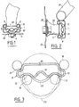
- the ball slide shown in the drawings, and in particular in FIG. 1, comprises an external element 1 formed by a U-shaped section profile provided with internal flanges 2 delimiting an opening 3.
- This profile 1 is fixed, for example by screws 4, on a fixed member 6.
- an internal element 8 which is hollow.
- the internal element 8 is constituted by a tube deformed so as to be substantially flattened and to comprise on each side a projecting lateral fin, 10, between two concave portions, respectively 12 and 14, for receiving the balls 16 from the slide. Between the two concave portions or grooves 12, the element 8 forms a longidutinal central boss, 18, while between the two grooves 14 the face of this same element 10 is substantially planar.
- the boss 18 comprises at regular intervals punctures 22 formed by pressing in the material without removing it, which practically constitute a rack.
- This section de.l'eursment tubulaire 8 is preferably obtained by deformation of a tube whose circular section is first elongated to take the shape indicated in phantom in Figure 3 and have the flat face 20.
- the curved part 23 of this blank is brought closer to the flat face 20 and deformed so as to constitute the two fins 10, as well as the concave grooves 12 and 14 and the boss 18.
- a tool associated with the assuring punch this deformation perforates the boss 18 and pushes the metal of this boss, as indicated in 19 in FIG. 3, to form the punctures 22.
- the material which constitutes this wall n 'having not undergone any modification nor indeed the very thickness of the wall. As a result, the tube retains all of its rigidity.
- the assembly of the slide has great strength and good mechanical strength.
- the U-shaped profile 1 is fixed to a fixed member while the internal element 8 is movable, but it is obvious that the slide could be mounted in the opposite direction, as shown for example, FIG. 2, the movable element 8 being fixed on a fixed member 26, for example a body portion, while the U-shaped section 1 is made integral with a movable member 24.
- the deformed part of the tube which constitutes the movable element 8 is preferably the central part of a tube which extends at each end of this deformed part and is terminated by lugs 28 fixing, for example on the member 26.
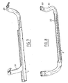
- the tube is then, as shown in FIG. 8, bent at each of the ends of the deformed central part 8 to form two projecting arms 30, each carrying at its end the tab 28 of fixation.
- Each arm 30 has a substantially circular section and is connected to the internal element 8 of the slide by a transition portion having a straight section that is simply elongated or oval, for example as shown in phantom in the lower part of FIG. 3, this which allows it to pass through the opening 3 of the profile 1.
- the arms 30 can thus easily move along this opening 3, as shown in FIG. 7. This arrangement makes it possible to reduce the length of the profile 1 and / or of the mobile element 8, while retaining a large clearance of the two slide organs.
- the element 8 and its arms 30 are preferably secured to the frame of the seat cushion, while the profile 1 is fixed to the floor of the vehicle, which allows the movable element 8 to be practically part of the frame of the seat and to give it a robust and relatively space-saving support, while allowing it appropriate mobility.
- the drive of the movable member can be carried out manually but it is preferably obtained by means of the rack formed by the punctures 22 of element 8.
- the section 1 is, in this case, pierced in its base 31, with an opening corresponding to one or preferably two punctures 22, which allows the engagement of each puncture with a drive pinion or any other similar device.
- the slide is simply locked in the position chosen by a locking device passing through the opening 32 of the bottom of the profile 1 and cooperating with the punctures 22.
- FIGS. 4 to 6 show such a locking device which comprises a lever 34 articulated at the lower part of the profile 1 in a notch 35 in the bottom of this profile.
- the lever 34 is provided with one, or preferably two, boss 36 which passes through the opening 32 and fits into the puncture 22 opposite this opening.
- a spring 38 in the shape of a stirrup, is fixed under the bottom 31 of the profile 1 and tends tightening the lever 34 against this bottom in the locking position of the punctures 22 and, consequently, of the element 8.
- the slide thus produced can be used for all kinds of applications. Although in FIGS. 7 and 8 the two elements 1 and 8 have straight cooperating portions and the trajectory of the slide is also rectilinear, it is clear that these elements can also be curved.
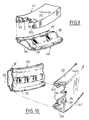
- the profile 1 can be curved around an axis transverse to its bottom 31 which then takes the form of a portion of cylinder.
- the internal element 48 is correspondingly curved, its flat face 20 becoming a portion of cylinder 46.
- Such a curvature practically does not modify the shape of the straight sections of these elements, so that the slide functions in the same way as the rectilinear slide.
- each end of the profile in a U , 1, 41 or 51 is provided with curved lugs for holding the balls, preventing their leakage outside the slide, in particular when the internal element is moving.
- these tabs are cut from the material of the profile itself.
- two legs 58 are cut in the opposite direction in the bottom 31 and folded inwards, in the direction of the flanges 2, so as to retain the two rows of balls 16 rolling on the bottom 31.
- Two other tabs 60 are cut in the extreme part of the flanges 2 and also folded in the direction of the bottom 31, so as to keep the balls 16 in contact with the flange 2.
- the movement of the arms 30, or of other end elements , in the slot 3 therefore never risks bringing out the balls and the slide can be used with safety.
Landscapes
- Engineering & Computer Science (AREA)
- Aviation & Aerospace Engineering (AREA)
- Transportation (AREA)
- Mechanical Engineering (AREA)
- Seats For Vehicles (AREA)
- Bearings For Parts Moving Linearly (AREA)
- Drawers Of Furniture (AREA)
Abstract
Description
- La présente invention concerne une glissière à billes, et tout particulièrement l'élément interne d'une telle glissière.
- Les glissières à billes comportent en général, actuellement, deux profilés, par exemple des profilés de section en U, emboîtés l'un dans l'autre, entre lesquels sont logées des billes permettant leur glissement relatif. Dans de nombreux cas toutefois, les profilés ne présentent pas une rigidité suffisante notamment lorsque le dispositif sur lequel ils sont montés risquent d'être soumis à des efforts brutaux. Par ailleurs, la fixation des profilés sur l'organe mobile et l'organe fixe nécessite l'adjonction de pièces annexes, ce qui complique la réalisation de l'ensemble.
- La présente invention a donc pour but de remédier à ces inconvénients en réalisant un élément interne destiné à être combiné à un profilé extérieur de section en U, muni de rebords, qui présente une grande rigidité et puisse facilement être adapté à des dispositifs divers.
- Cette invention a pour objet un élément interne de glissière à billes, qui est constitué par un tube déformé, de façon à être relativement aplati et à former de chaque côté une saillie latérale entre deux parties concaves de réception des billes.
- L'élément interne, étant ainsi réalisé par déformation d'un tube dont l'épaisseur de paroi n'est pas modifiée, présente une rigidité importante. Par ailleurs, la retenue de l'élément interne dans le profilé extérieur est due à la présence des ailettes qui font saillie par rapport au tube initial, mais sont absentes dans une portion de transition avec le tube de section circulaire non déformé. Une telle portion de transition peut donc traverser l'ouverture du profilé extérieur, ce qui permet au tube non déformé d'être fixé à l'extérieur du profilé sur l'organe fixe ou l'organe mobile , selon les utilisations.
- Dans un mode de réalisation, l'élément interne comporte un bossage central entre deux des parties concaves et ce bossage est percé de crevés régulièrement espacés, constituant une crémaillère, de sorte qu'il peut coopérer avec un dispositif de verrouillage ou d'entraînement.
- Un tel élément est tout particulièrement adapté à la réalisation d'un mécanisme de glissière de siège de véhicule automobile, l'un des éléments de la glissière étant fixé sur la carrosserie du véhicule tandis que l'autre est solidaire de l'armature du siège.
- La description ci-dessous de modes de réalisation donnés à titre d'exemples non limitatifs, et représentés aux dessins annexés, fera d'ailleurs ressortir les avantages et caractéristiques de l'invention.
- Sur ces dessins :
- - la fig. 1 est une vue en coupe verticale d'une glissière à billes comportant un élément selon l'invention;
- - la fig. 2 est une vue analogue à la figure 1 d'une variante de réalisation;
- - la fig. 3 est une vue à plus grande échelle de l'élément de glissière de l'invention, montrant ses différentes phases de fabrication;
- - la fig. 4 est une vue en coupe du mécanisme de glissière au droit d'un dispositif de verrouillage;
- - la fig. 5 est une vue de dessous de la portion de glissière de la figure 4;
- - la fig. 6 est une vue en coupe suivant la ligne F-F de la figure 5;
- - la fig. 7 est une vue en perspective d'un mécanisme de glissière plus particulièrement destiné à un siège de véhicule automobile;
- - la fig. 8 est une vue en perspective de l'élément interne de la glissière de la figure 7;
- - les fig. 9 et 10 sont des vues partielles, en perspective éclatée, de deux variantes de réalisation d'une glissière selon l'invention.
- La glissière à billes représentée sur les dessins, et notamment sur la figure 1, comporte un élément extérieur 1 formé par un profilé de section en U muni de rebords internes 2 délimitant une ouverture 3. Ce profilé 1 est fixé, par exemple par des vis 4, sur un organe fixe 6. A l'intérieur de ce profilé 1 est monté un élément interne 8 qui est creux.
- Comme le montrent plus particulièrement les figures 1 à 3, l'élément interne 8 est constitué par un tube déformé de façon à être sensiblement aplati et à comporter de chaque côté une ailette latérale en saillie, 10, entre deux portions concaves, respectivement 12 et 14, de réception des billes 16 de la glissière. Entre les deux portions concaves ou rainures 12, l'élément 8 forme un bossage central longidutinal, 18, tandis qu'entre les deux rainures 14 la face de ce même élément 10 est sensiblement plane.
- De préférence, le bossage 18 comporte à intervalles réguliers des crevés 22 formés par enfoncement de la matière sans enlèvement de celle-ci, qui constituent pratiquement une crémaillère.
- Cette section de.l'élément tubulaire 8 est obtenue de préférence par déformation d'un tube dont la section circulaire est d'abord allongée pour prendre la forme indiquée en trait mixte sur la figure 3 et comporter la face plane 20. Au cours d'une seconde phase de déformation, la partie incurvée 23 de cette ébauche est rapprochée de la face plane 20 et déformée de façon à constituer les deux ailettes 10, de même que les rainures concaves 12 et 14 et le bossage 18. Un outil associé au poinçon assurant cette déformation perfore le bossage 18 et repousse le métal de ce bossage, comme indiqué en 19 sur la figure 3, pour former les crevés 22. Dans une telle déformation seule la paroi du tube a changé de forme, la matière qui constitue cette paroi n'ayant pas subi de modification, ni d'ailleurs l'épaisseur même de la paroi. Par suite, le tube conserve toute sa rigidité.
- Comme l'élément interne 8 est maintenu dans le profilé 1 par la coopération de ses ailettes 10 avec les billes 16 et les rebords 2, l'ensemble de la glissière présente une grande résistance et une bonne tenue mécanique.
- Dans le mode de réalisation représenté sur la figure l, le profilé en U 1 est fixé sur un organe fixe tandis que l'élément interne 8 est mobile, mais il est bien évident que la glissière pourrait être montée en sens inverse, comme le montre par exemple la figure 2, l'élément mobile 8 étant fixé sur un organe fixe 26, par exemple une portion de carrosserie, tandis que le profilé en U 1 est rendu solidaire d'un organe mobile 24.
- Quel que soit le mode de réalisation, la partie déformée du tube qui constitue l'élément mobile 8 est, de préférence, la partie centrale d'un tube qui se prolonge à chacune des extrémités de cette partie déformée et est terminée par des pattes 28 de fixation, par exemple sur l'organe 26. Le tube est alors, comme le montre la figure 8, recourbé à chacune des extrémités de la partie centrale déformée 8 pour constituer deux bras 30 en saillie, portant chacun_à son extrémité la patte 28 de fixation.
- Chaque bras 30 a une section sensiblement circulaire et est relié à l'élément interne 8 de la glissière par une portion de transition ayant une section droite simplement allongée ou ovalisée, par exemple comme montré en trait mixte à la partie inférieure de la figure 3, ce qui lui permet de traverser l'ouverture 3 du profilé 1.
- Les bras 30 peuvent ainsi facilement se déplacer le long de cette ouverture 3, comme le montre la figure 7. Cette disposition permet de réduire la longueur du profilé 1 et/ou de l'élément mobile 8, tout en conservant un débattement important des deux organes de la glissière.
- Dans le cas d'un siège de véhicule automobile, l'élément 8 et ses bras 30 sont de préférence solidaires de l'armature de l'assise du siège, tandis que le profilé 1 est fixé sur le plancher du véhicule, ce qui permet à l'élément mobile 8 de faire pratiquement partie de l'armature du siège et de donner à celui-ci un support robuste et relativement peu encombrant, tout en lui permettant une mobilité appropriée.
- Bien entendu, l'entraînement de l'organe mobile, que ce soit le profilé 1 ou l'élément interne 8, peut être effectué manuellement mais il est, de préférence, obtenu par l'intermédiaire de la crémaillère formée par les crevés 22 de l'élément 8. Le profilé 1 est, dans ce cas, percé dans sa base 31, d'une ouverture correspondant à un ou de préférence deux crevés 22, qui permet l'engrènement de chaque crevé avec un pignon d'entraînement ou tout autre dispositif analogue.
- Selon un autre mode de réalisation, la glissière est simplement verrouillée dans la position choisie par un dispositif de verrouillage traversant l'ouverture 32 du fond du profilé 1 et coopérant avec les crevés 22. Les figures 4 à 6 montrent un tel dispositif de verrouillage qui comporte un levier 34 articulé à la partie inférieure du profilé 1 dans une encoche 35 du fond de ce profilé. Le levier 34 est muni d'un, ou de préférence deux, bossage 36 qui traverse l'ouverture 32 et s'emboîte dans le crevé 22 en regard de cette ouverture. Un ressort 38, en forme d'étrier, est fixé sous le fond 31 du profilé 1 et tend à serrer le levier 34 contre ce fond dans la position de verrouillage des crevés 22 et, par suite, de l'élément 8.
- Un effort sur le levier 34 suffit à écarter les bossages 32 des crevés 22 contre l'action du ressort 38 et libère ainsi l'élément interne 8 qui peut se déplacer par rapport au profilé 1. Dès que le levier 34 est rela- ché, le ressort 38 le rappelle contre le profilé 1 ce qui verrouille immédiatement la glissière.
- Bien entendu, le même dispositif peut être utilisé, que le profilé soit fixe ou mobile, qu'il soit horizontal ou vertical.
- La glissière ainsi réalisée peut être utilisée pour toutes sortes d'applications. Bien que sur les figures 7 et 8 les deux éléments 1 et 8 aient des portions coopérantes rectilignes et que la trajectoire de la glissière soit également rectiligne, il est clair que ces éléments peuvent également être incurvés.
- Par exemple, comme le montre la figure 9, le profilé 1 peut être incurvé autour d'un axe transversal à son fond 31 qui prend alors la forme d'une portion de cylindre. L'élément interne 48 est incurvé de manière correspondante, sa face plane 20 devenant une portion de cylindre 46. Une telle courbure ne modifie pratiquement pas la forme des sections droites de ces éléments, de sorte que la glissière fonctionne de la même manière que la glissière rectiligne.
- C'est également le cas de la glissière 51-58 de la figure 10, dont les deux éléments sont incurvés autour d'un axe perpendiculaire au fond 31 du profilé 51 et à la face plane 56 de l'élément interne 58. Les deux côtés 52, 54 du U du profilé 51 forment alors deux portions de cylindre tandis que les ailettes 8, 10 de 1 élément interne constituent deux portions d'anneau.
- Quelle que soit la forme de la glissière et de la trajectoire de coulissement, chaque extrémité du profilé en U, 1, 41 ou 51, est munie de pattes recourbées de maintien des billes, interdisant leur fuite à l'extérieur de la glissière, notamment lors du déplacement de l'élément interne. De préférence, ces pattes sont découpées dans la matière du profilé lui-même. Par exemple, deux pattes 58 sont découpées en sens inverse dans le fond 31 et rabattues vers l'intérieur, en direction des rebords 2, de façon à retenir les deux rangées de billes 16 roulant sur le fond 31.
- Deux autres pattes 60 sont découpées dans la partie extrême des rebords 2 et également repliées en direction du fond 31, de façon à maintenir les billes 16 en contact avec le rebord 2. Le déplacement des bras 30,ou d'autres éléments d'extrémité, dans la fente 3 ne risque donc jamais de faire sortir les billes et la glissière peut être utilisée avec sécurité.
Claims (9)
Applications Claiming Priority (2)
| Application Number | Priority Date | Filing Date | Title |
|---|---|---|---|
| FR8306233A FR2544415B1 (fr) | 1983-04-15 | 1983-04-15 | Element de glissiere a billes et glissiere ainsi realisee |
| FR8306233 | 1983-04-15 |
Publications (2)
| Publication Number | Publication Date |
|---|---|
| EP0123601A1 true EP0123601A1 (fr) | 1984-10-31 |
| EP0123601B1 EP0123601B1 (fr) | 1987-04-08 |
Family
ID=9287920
Family Applications (1)
| Application Number | Title | Priority Date | Filing Date |
|---|---|---|---|
| EP84400708A Expired EP0123601B1 (fr) | 1983-04-15 | 1984-04-10 | Glissière à billes |
Country Status (8)
| Country | Link |
|---|---|
| US (1) | US4569563A (fr) |
| EP (1) | EP0123601B1 (fr) |
| JP (1) | JPS6049118A (fr) |
| CA (1) | CA1236390A (fr) |
| DE (1) | DE3463017D1 (fr) |
| ES (1) | ES279013Y (fr) |
| FR (1) | FR2544415B1 (fr) |
| ZA (1) | ZA842768B (fr) |
Cited By (7)
| Publication number | Priority date | Publication date | Assignee | Title |
|---|---|---|---|---|
| GB2188543A (en) * | 1986-04-07 | 1987-10-07 | Nissan Motor | Seat slide device |
| FR2604131A1 (fr) * | 1986-09-19 | 1988-03-25 | Cousin Cie Ets A & M Freres | Glissieres courbes commandees |
| EP0568900A1 (fr) * | 1992-05-02 | 1993-11-10 | ITT Automotive Europe GmbH | Système à deux glissières de forme en U à encombrement réduit, en particulier pour sièges de véhicules automobiles |
| WO1997046409A1 (fr) * | 1996-06-06 | 1997-12-11 | Lear Corporation | Dispositif de reglage de siege de vehicule actionne par moteur a ensembles glissieres a blocage automatique |
| DE202008007684U1 (de) * | 2008-06-09 | 2009-10-22 | Paul Hettich Gmbh & Co. Kg | Ausziehführung |
| WO2013017633A1 (fr) * | 2011-08-01 | 2013-02-07 | C. Rob. Hammerstein Gmbh & Co. Kg | Glissière pour un système de réglage longitudinal d'un siège de véhicule automobile et procédé de production d'une telle glissière |
| WO2013017632A3 (fr) * | 2011-08-01 | 2013-05-10 | C. Rob. Hammerstein Gmbh & Co. Kg | Mécanisme de commande pour une glissière d'un système de réglage longitudinal d'un siège de véhicule automobile |
Families Citing this family (21)
| Publication number | Priority date | Publication date | Assignee | Title |
|---|---|---|---|---|
| JPS6173829U (fr) * | 1984-10-18 | 1986-05-19 | ||
| GB8529940D0 (en) * | 1985-12-04 | 1986-01-15 | Jackson P A S | Ball slide system |
| JPH0182326U (fr) * | 1987-11-24 | 1989-06-01 | ||
| US4787756A (en) * | 1988-02-26 | 1988-11-29 | General Motors Corporation | Apparatus and method of seat adjuster slide |
| JPH02110540U (fr) * | 1989-02-22 | 1990-09-04 | ||
| JPH03199569A (ja) * | 1989-12-27 | 1991-08-30 | Sekisui Chem Co Ltd | 外廊下の床構造 |
| DE4238486A1 (de) * | 1992-04-27 | 1993-10-28 | Hammerstein Gmbh C Rob | Längsführung für Längsverstelleinrichtungen von Fahrzeugsitzen |
| US5624171A (en) * | 1995-07-24 | 1997-04-29 | Durham Manufacturing Company | Two-track drawer slide having function of three-track slide |
| US5746409A (en) * | 1996-07-19 | 1998-05-05 | Excellence Manufacturing, Inc. | Reinforced seat track |
| FR2755653B1 (fr) * | 1996-11-14 | 1999-01-08 | Faure Bertrand Equipements Sa | Glissiere pour siege de vehicule, et siege equipe d'une telle glissiere |
| US6254163B1 (en) | 2000-05-15 | 2001-07-03 | Lear Corporation | Vehicle seat track attachment assembly |
| USD448050S1 (en) | 2000-09-28 | 2001-09-18 | Edina Technical Products, Inc. | Pinball gumball vendor |
| JP4299069B2 (ja) * | 2003-07-15 | 2009-07-22 | Thk株式会社 | スライドレール |
| FR2898555B1 (fr) * | 2006-03-17 | 2009-02-13 | Faurecia Sieges Automobile | Glissiere renflee pour siege de vehicule |
| KR101000744B1 (ko) * | 2007-11-05 | 2010-12-14 | 박윤식 | 하부장착형 슬라이드 및 그 제조방법 |
| CN102170809B (zh) * | 2008-07-28 | 2014-02-26 | Segos株式会社 | 底部安装型滑轨及其制造方法 |
| JP5927970B2 (ja) * | 2012-02-15 | 2016-06-01 | アイシン精機株式会社 | 車両用シートスライド装置 |
| DE102013109380A1 (de) * | 2013-08-29 | 2015-03-05 | Rennerich Gmbh | Linearführungsvorrichtung |
| DE202015104668U1 (de) * | 2015-09-03 | 2015-10-07 | Reme-Möbelbeschläge Gmbh | Vollauszugsführung für Möbelteile |
| DE102016225818B4 (de) * | 2016-09-21 | 2021-05-12 | Adient Luxembourg Holding S.À R.L. | Längseinsteller sowie Fahrzeugsitz |
| TWI818879B (zh) | 2023-03-27 | 2023-10-11 | 川湖科技股份有限公司 | 滑軌總成及其滑軌 |
Citations (6)
| Publication number | Priority date | Publication date | Assignee | Title |
|---|---|---|---|---|
| US2195349A (en) * | 1939-03-24 | 1940-03-26 | L M Payne Company | Seat slide structure |
| DE826552C (de) * | 1949-08-23 | 1952-01-03 | Cox & Co Watford Ltd | Gleitfuehrung fuer Fahrzeugsitze oder sonstige Gleitkoerper |
| FR2151928A5 (fr) * | 1971-08-28 | 1973-04-20 | Hr Turner Ltd | |
| FR2310239A1 (fr) * | 1975-05-05 | 1976-12-03 | Riehle Otto | Glissiere pour sieges de vehicule deplacables vers l'avant et vers l'arriere |
| FR2419839A1 (fr) * | 1978-03-15 | 1979-10-12 | Tubauto | Dispositif de maintien d'un siege sur le plancher d'un vehicule |
| GB2071486A (en) * | 1980-02-22 | 1981-09-23 | Cox T I Ltd | Vehicle seat slides |
Family Cites Families (4)
| Publication number | Priority date | Publication date | Assignee | Title |
|---|---|---|---|---|
| FR1349301A (fr) * | 1962-11-27 | 1964-01-17 | Anciens Etablissements Panhard | Perfectionnements apportés aux dispositifs de fixation des sièges avant sur les véhicules automobiles |
| GB1421660A (en) * | 1973-02-09 | 1976-01-21 | Turner Willenhall Ltd H R | Seat sliders |
| DE2605997A1 (de) * | 1976-02-14 | 1977-08-18 | Riehle Fa Otto | Gleitfuehrung fuer in fahrzeuglaengsrichtung verschiebbare sitze |
| JPS58152631A (ja) * | 1982-03-05 | 1983-09-10 | Nissan Motor Co Ltd | 車両用シ−トスライド装置 |
-
1983
- 1983-04-15 FR FR8306233A patent/FR2544415B1/fr not_active Expired
-
1984
- 1984-04-10 EP EP84400708A patent/EP0123601B1/fr not_active Expired
- 1984-04-10 DE DE8484400708T patent/DE3463017D1/de not_active Expired
- 1984-04-13 ES ES1984279013U patent/ES279013Y/es not_active Expired
- 1984-04-13 ZA ZA842768A patent/ZA842768B/xx unknown
- 1984-04-13 CA CA000451917A patent/CA1236390A/fr not_active Expired
- 1984-04-16 JP JP59076399A patent/JPS6049118A/ja active Granted
- 1984-04-16 US US06/600,716 patent/US4569563A/en not_active Expired - Lifetime
Patent Citations (6)
| Publication number | Priority date | Publication date | Assignee | Title |
|---|---|---|---|---|
| US2195349A (en) * | 1939-03-24 | 1940-03-26 | L M Payne Company | Seat slide structure |
| DE826552C (de) * | 1949-08-23 | 1952-01-03 | Cox & Co Watford Ltd | Gleitfuehrung fuer Fahrzeugsitze oder sonstige Gleitkoerper |
| FR2151928A5 (fr) * | 1971-08-28 | 1973-04-20 | Hr Turner Ltd | |
| FR2310239A1 (fr) * | 1975-05-05 | 1976-12-03 | Riehle Otto | Glissiere pour sieges de vehicule deplacables vers l'avant et vers l'arriere |
| FR2419839A1 (fr) * | 1978-03-15 | 1979-10-12 | Tubauto | Dispositif de maintien d'un siege sur le plancher d'un vehicule |
| GB2071486A (en) * | 1980-02-22 | 1981-09-23 | Cox T I Ltd | Vehicle seat slides |
Cited By (11)
| Publication number | Priority date | Publication date | Assignee | Title |
|---|---|---|---|---|
| GB2188543A (en) * | 1986-04-07 | 1987-10-07 | Nissan Motor | Seat slide device |
| GB2188543B (en) * | 1986-04-07 | 1990-05-23 | Nissan Motor | Seat slide device |
| FR2604131A1 (fr) * | 1986-09-19 | 1988-03-25 | Cousin Cie Ets A & M Freres | Glissieres courbes commandees |
| EP0264307A1 (fr) * | 1986-09-19 | 1988-04-20 | A. & M. COUSIN Etablissements COUSIN FRERES | Glissières courbes commandées |
| EP0568900A1 (fr) * | 1992-05-02 | 1993-11-10 | ITT Automotive Europe GmbH | Système à deux glissières de forme en U à encombrement réduit, en particulier pour sièges de véhicules automobiles |
| WO1997046409A1 (fr) * | 1996-06-06 | 1997-12-11 | Lear Corporation | Dispositif de reglage de siege de vehicule actionne par moteur a ensembles glissieres a blocage automatique |
| DE202008007684U1 (de) * | 2008-06-09 | 2009-10-22 | Paul Hettich Gmbh & Co. Kg | Ausziehführung |
| WO2013017633A1 (fr) * | 2011-08-01 | 2013-02-07 | C. Rob. Hammerstein Gmbh & Co. Kg | Glissière pour un système de réglage longitudinal d'un siège de véhicule automobile et procédé de production d'une telle glissière |
| WO2013017632A3 (fr) * | 2011-08-01 | 2013-05-10 | C. Rob. Hammerstein Gmbh & Co. Kg | Mécanisme de commande pour une glissière d'un système de réglage longitudinal d'un siège de véhicule automobile |
| US9046159B2 (en) | 2011-08-01 | 2015-06-02 | Johnson Controls Metals and Mechanisms GmbH & Co. | Actuating drive for a rail guide of a longitudinal adjustment of a motor vehicle seat |
| US9050907B2 (en) | 2011-08-01 | 2015-06-09 | Johnson Controls Metals and Mechanisms GmbH & Co. | Rail guide for a longitudinal adjustment of a motor vehicle seat and method for producing such a rail guide |
Also Published As
| Publication number | Publication date |
|---|---|
| ES279013Y (es) | 1986-10-01 |
| ZA842768B (en) | 1984-11-28 |
| DE3463017D1 (en) | 1987-05-14 |
| US4569563A (en) | 1986-02-11 |
| EP0123601B1 (fr) | 1987-04-08 |
| ES279013U (es) | 1986-03-01 |
| JPS638329B2 (fr) | 1988-02-22 |
| JPS6049118A (ja) | 1985-03-18 |
| FR2544415B1 (fr) | 1986-09-05 |
| CA1236390A (fr) | 1988-05-10 |
| FR2544415A1 (fr) | 1984-10-19 |
Similar Documents
| Publication | Publication Date | Title |
|---|---|---|
| EP0123601B1 (fr) | Glissière à billes | |
| EP0688695B1 (fr) | Système de verrouillage d'un élément mobile d'un siège de véhicule automobile | |
| EP0493182A1 (fr) | Collier de fixation | |
| FR2865492A1 (fr) | Ensemble de verrouillage, notamment d'un element mobile de fermeture, et combinaison l'utilisant | |
| FR2551810A1 (fr) | Dispositif de retenue a ressort et procede d'assemblage associe | |
| EP3882422A1 (fr) | Verrou pour panneau d'aéronef | |
| EP0524053B1 (fr) | Glissière pour siège de véhicule comportant un dispositif de réduction des jeux et d'élimination des bruits | |
| EP3203000A1 (fr) | Serrure d'ouvrant à embase élastiquement emboîtable | |
| EP0443895A1 (fr) | Dispositif de verrouillage de deux tubes coaxiaux | |
| EP2369186B1 (fr) | Dispositif de fixation de type "quart de tour" | |
| EP1352180B1 (fr) | Frein de parc et son dispositif de commande. | |
| FR2828861A1 (fr) | Frein de stationnement pour un vehicule | |
| EP2017408B1 (fr) | Dispositif de prépositionnement d'une gâche destinée à coopérer avec une serrure d'un ouvrant de véhicule automobile et véhicule automobile comportant au moins un tel dispositif | |
| FR2925456A1 (fr) | Planche de bord de vehicule automobile avec pion centreur integre | |
| EP0296961B1 (fr) | Dispositif de fixation | |
| FR2697566A1 (fr) | Serrure à pêne basculant. | |
| FR2652627A1 (fr) | Accessoire de jonction pour chaine de transmission. | |
| FR2733285A1 (fr) | Dispositif de fixation mecanique rigide destine a une rotule, ensemble le comprenant et procedes de montage et demontage | |
| CH713218B1 (fr) | Dispositif de fixation rapide d'un bracelet de montre. | |
| EP0663499B1 (fr) | Clé à barillet de sûreté de manoeuvre d'une serrure et barillet actionnable par une telle clé | |
| FR2732083A1 (fr) | Dispositif de connexion a montage simplifie pour assembler deux profiles | |
| FR2999252A1 (fr) | Dispositif pour une installation de controle de pieces munies d'inserts de fixation par encliquetage. | |
| FR2540388A1 (fr) | Raquette de tennis | |
| EP1300535B1 (fr) | Butée réglable pour éléments mobiles de carrosserie de véhicule automobile | |
| EP1717459A1 (fr) | Dispositif de fixation d'une pièce à un panneau comportant un ensemble formé par un organe de cage et un organe d'insert et procédé de réalisation d'un tel ensemble |
Legal Events
| Date | Code | Title | Description |
|---|---|---|---|
| PUAI | Public reference made under article 153(3) epc to a published international application that has entered the european phase |
Free format text: ORIGINAL CODE: 0009012 |
|
| AK | Designated contracting states |
Designated state(s): BE DE GB IT LU NL SE |
|
| 17P | Request for examination filed |
Effective date: 19850206 |
|
| ITF | It: translation for a ep patent filed | ||
| GRAA | (expected) grant |
Free format text: ORIGINAL CODE: 0009210 |
|
| AK | Designated contracting states |
Kind code of ref document: B1 Designated state(s): BE DE GB IT LU NL SE |
|
| REF | Corresponds to: |
Ref document number: 3463017 Country of ref document: DE Date of ref document: 19870514 |
|
| PLBE | No opposition filed within time limit |
Free format text: ORIGINAL CODE: 0009261 |
|
| STAA | Information on the status of an ep patent application or granted ep patent |
Free format text: STATUS: NO OPPOSITION FILED WITHIN TIME LIMIT |
|
| 26N | No opposition filed | ||
| PGFP | Annual fee paid to national office [announced via postgrant information from national office to epo] |
Ref country code: LU Payment date: 19910410 Year of fee payment: 8 |
|
| EPTA | Lu: last paid annual fee | ||
| PG25 | Lapsed in a contracting state [announced via postgrant information from national office to epo] |
Ref country code: LU Free format text: LAPSE BECAUSE OF NON-PAYMENT OF DUE FEES Effective date: 19920410 |
|
| REG | Reference to a national code |
Ref country code: GB Ref legal event code: 732 |
|
| BECA | Be: change of holder's address |
Free format text: 920928 COMPAGNIE EUROPEENNE DE SIEGES POUR AUTOMOBILES *CESA:20 RUE PAUL VAILLANT-COUTURIER, 92300 LEVALLOIS-PERRET |
|
| BECH | Be: change of holder |
Free format text: 920928 COMPAGNIE EUROPEENNE DE SIEGES POUR AUTOMOBILES *CESA |
|
| BECN | Be: change of holder's name |
Effective date: 19920828 |
|
| ITPR | It: changes in ownership of a european patent |
Owner name: CAMBIO RAGIONE SOCIALE;ECIA - EQUIPEMENTS ET COMPO |
|
| ITTA | It: last paid annual fee | ||
| NLS | Nl: assignments of ep-patents |
Owner name: ACIERS ET OUTILLAGE PEUGEOT S.A. TE AUDINCOURT, FR |
|
| NLT1 | Nl: modifications of names registered in virtue of documents presented to the patent office pursuant to art. 16 a, paragraph 1 |
Owner name: ECIA-EQUIPEMENTS ET COMPOSANTS POUR L'INDUSTRIE AU |
|
| NLS | Nl: assignments of ep-patents |
Owner name: CESA-COMPAGNIE EUROPEENNE DE SIEGES POUR AUTOMOBIL |
|
| EAL | Se: european patent in force in sweden |
Ref document number: 84400708.8 |
|
| PGFP | Annual fee paid to national office [announced via postgrant information from national office to epo] |
Ref country code: NL Payment date: 19970320 Year of fee payment: 14 |
|
| PGFP | Annual fee paid to national office [announced via postgrant information from national office to epo] |
Ref country code: DE Payment date: 19970321 Year of fee payment: 14 |
|
| PGFP | Annual fee paid to national office [announced via postgrant information from national office to epo] |
Ref country code: GB Payment date: 19970404 Year of fee payment: 14 |
|
| PGFP | Annual fee paid to national office [announced via postgrant information from national office to epo] |
Ref country code: SE Payment date: 19970425 Year of fee payment: 14 |
|
| PGFP | Annual fee paid to national office [announced via postgrant information from national office to epo] |
Ref country code: BE Payment date: 19970515 Year of fee payment: 14 |
|
| PG25 | Lapsed in a contracting state [announced via postgrant information from national office to epo] |
Ref country code: GB Free format text: LAPSE BECAUSE OF NON-PAYMENT OF DUE FEES Effective date: 19980410 |
|
| PG25 | Lapsed in a contracting state [announced via postgrant information from national office to epo] |
Ref country code: SE Free format text: LAPSE BECAUSE OF NON-PAYMENT OF DUE FEES Effective date: 19980411 |
|
| PG25 | Lapsed in a contracting state [announced via postgrant information from national office to epo] |
Ref country code: BE Free format text: LAPSE BECAUSE OF NON-PAYMENT OF DUE FEES Effective date: 19980430 |
|
| BERE | Be: lapsed |
Owner name: COMPAGNIE EUROPEENNE DE SIEGES POUR AUTOMOBILES Effective date: 19980430 |
|
| PG25 | Lapsed in a contracting state [announced via postgrant information from national office to epo] |
Ref country code: NL Free format text: LAPSE BECAUSE OF NON-PAYMENT OF DUE FEES Effective date: 19981101 |
|
| GBPC | Gb: european patent ceased through non-payment of renewal fee |
Effective date: 19980410 |
|
| NLV4 | Nl: lapsed or anulled due to non-payment of the annual fee |
Effective date: 19981101 |
|
| EUG | Se: european patent has lapsed |
Ref document number: 84400708.8 |
|
| PG25 | Lapsed in a contracting state [announced via postgrant information from national office to epo] |
Ref country code: DE Free format text: LAPSE BECAUSE OF NON-PAYMENT OF DUE FEES Effective date: 19990202 |