EP0123640A1 - Umdrehungssteuerungsgerät - Google Patents
Umdrehungssteuerungsgerät Download PDFInfo
- Publication number
- EP0123640A1 EP0123640A1 EP84630062A EP84630062A EP0123640A1 EP 0123640 A1 EP0123640 A1 EP 0123640A1 EP 84630062 A EP84630062 A EP 84630062A EP 84630062 A EP84630062 A EP 84630062A EP 0123640 A1 EP0123640 A1 EP 0123640A1
- Authority
- EP
- European Patent Office
- Prior art keywords
- relay
- circuit
- switch
- motor
- motor relay
- Prior art date
- Legal status (The legal status is an assumption and is not a legal conclusion. Google has not performed a legal analysis and makes no representation as to the accuracy of the status listed.)
- Ceased
Links
- 230000004044 response Effects 0.000 claims abstract description 7
- 239000007858 starting material Substances 0.000 claims description 11
- 230000003111 delayed effect Effects 0.000 claims 1
- 230000000994 depressogenic effect Effects 0.000 description 9
- 238000012423 maintenance Methods 0.000 description 9
- 238000004140 cleaning Methods 0.000 description 3
- 238000001514 detection method Methods 0.000 description 2
- 230000000694 effects Effects 0.000 description 2
- 238000012986 modification Methods 0.000 description 2
- 230000004048 modification Effects 0.000 description 2
- 230000008439 repair process Effects 0.000 description 2
- 238000009987 spinning Methods 0.000 description 2
- 230000008859 change Effects 0.000 description 1
- 238000010586 diagram Methods 0.000 description 1
- 230000009977 dual effect Effects 0.000 description 1
- 230000000737 periodic effect Effects 0.000 description 1
- 239000007787 solid Substances 0.000 description 1
- 230000001629 suppression Effects 0.000 description 1
- 238000004804 winding Methods 0.000 description 1
Images
Classifications
-
- G—PHYSICS
- G02—OPTICS
- G02F—OPTICAL DEVICES OR ARRANGEMENTS FOR THE CONTROL OF LIGHT BY MODIFICATION OF THE OPTICAL PROPERTIES OF THE MEDIA OF THE ELEMENTS INVOLVED THEREIN; NON-LINEAR OPTICS; FREQUENCY-CHANGING OF LIGHT; OPTICAL LOGIC ELEMENTS; OPTICAL ANALOGUE/DIGITAL CONVERTERS
- G02F1/00—Devices or arrangements for the control of the intensity, colour, phase, polarisation or direction of light arriving from an independent light source, e.g. switching, gating or modulating; Non-linear optics
- G02F1/01—Devices or arrangements for the control of the intensity, colour, phase, polarisation or direction of light arriving from an independent light source, e.g. switching, gating or modulating; Non-linear optics for the control of the intensity, phase, polarisation or colour
- G02F1/13—Devices or arrangements for the control of the intensity, colour, phase, polarisation or direction of light arriving from an independent light source, e.g. switching, gating or modulating; Non-linear optics for the control of the intensity, phase, polarisation or colour based on liquid crystals, e.g. single liquid crystal display cells
-
- F—MECHANICAL ENGINEERING; LIGHTING; HEATING; WEAPONS; BLASTING
- F16—ENGINEERING ELEMENTS AND UNITS; GENERAL MEASURES FOR PRODUCING AND MAINTAINING EFFECTIVE FUNCTIONING OF MACHINES OR INSTALLATIONS; THERMAL INSULATION IN GENERAL
- F16P—SAFETY DEVICES IN GENERAL; SAFETY DEVICES FOR PRESSES
- F16P3/00—Safety devices acting in conjunction with the control or operation of a machine; Control arrangements requiring the simultaneous use of two or more parts of the body
- F16P3/18—Control arrangements requiring the use of both hands
- F16P3/20—Control arrangements requiring the use of both hands for electric control systems
Definitions
- the present invention relates to a rotation control circuit and more particularly to a circuit for facilitating the positioning or maintenance of motor driven equipment by providing a jog control.
- jog will be construed to be a rotational movement of a spinning device through an increment sufficient to bring a particular station or spindle into its proper position for adjustment, maintenance, cleaning or other purpose.
- Such discrete rotation or jog is difficult to attain in that rotating equipment will tend to rotate at line speed as long as the motor is energized.
- the operator must momentarily depress a push button or the like in order to briefly energize the motor and then wait to see where the rotating equipment will stop. If the position of the equipment is not that which is required, the operator will have to repeatedly energize the motor momentarily until the required position is attained.
- this operation may also be considered a safety hazard in that such maintenance type of operation is generally done without the usual safety shields or other internal safety features of the equipment in effect.
- the present invention may comprise a rotation control circuit having the power supply and a motor relay operable to be energized by the power supply.
- a circuit for intermittently energizing the motor relay is provided which comprises a first switch means connected to the power supply and a second switch means connecting the first switch means to the motor relay.
- the second switch means is a normally closed switch means.
- a timer is provided which is connected to the first switch means and which is operable, in response to the closing of the first switch means, to generate a signal after a predetermined time interval whereby the second switch means will be open and remain open.
- the motor relay will only be energized during the predetermined time interval.
- the first switch means comprises two series connected switches, both of which must be closed in order to energize the motor relay.
- This is a safety feature which requires the operator to use both hands while operating the equipment in the intermittent or jog mode.
- the switches be push-button operated and bias opened so that they must remain depressed by the operator in order to stay closed.
- the timer circuit comprises a means such as a monostable multivibrator for setting a predetermined time interval in accordance with the rotation needed to present each successive station of the associated equipment.
- the timer circuit is connected to a first switch relay and the second switch means is responsive to the first switch relay to open the circuit to the motor relay after the expiration of the predetermined time interval.
- the rotation control circuit is also provided with a circuit for continuously energizing the motor relay.
- This circuit may comprise a starter switch connected between the first switch relay and the system power supply and a further switch, responsive to said first switch relay, connected between the starter switch and the motor relay.
- the further switch may advantageously be a normally open switch which is closed in response to the energization of the first switch relay.
- the starter switch is a normally opened, biased open push-button switch and the continuous energization circuit comprises a latching means for holding the control circuit "on" after the start button is pushed.
- the continuous energization circuit will advantageously include a normally closed, biased closed stop switch connected in series with the start switch and the latching means to enable the operator to stop the continuous energization of the motor relay at will.
- a fifth switch may be provided in series with the starter switch and the latching means.
- the fifth switch is preferably a normally closed, relay operating switch responsive to a third relay and operable to open in response to the energization of the third relay to thereby interlock the continuous energization of the motor relay.
- the third relay may be connected to an open terminal of a fault detector so as to automatically energize the third relay upon occurrence of a fault to thereby interrupt continuous operation of the motor relay.
- the third relay may also be connected to a jog signal terminal to thereby automatically interrupt continuous operation of the motor relay upon occurrence of a jog signal.
- the entire control circuit including the motor relay, is energized by a low voltage DC (e.g. 12 volt DC) power supply which is the same power supply used to operate the entire control system of the associated equipment.
- a low voltage DC e.g. 12 volt DC
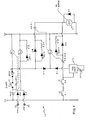
- a rotation control circuit 10 is provided for controlling the position of a rotating mandrel or spindle or the like which is driven by an electric motor, typically through a variable belt drive or the like as described in U.S. Patent No. 3,800,400, the disclosure of which is hereby incorporated by reference.
- a heavy duty relay means is provided to energize the driving motor.
- Such a relay may comprise the motor relay 12 which is interposed between the motor windings and the control circuit and which is preferably energized by the low voltage (e.g. 12v D.C.) source (+,-) which functions as a power supply for the control circuit 10.
- means are provided to prevent any back EMF from the motor relay 12 from surging back into the solid state circuit 10.
- Such means may include suppression diode D 5 which is connected so as to shunt the relay 12.
- the motor relay 12 may comprise a magnetic coil of about 12v D.C.-10 amp capacity which can be used as a relay for a 5 h.p., 220V, 3 motor as may be used with the spinwelder of the above referenced patent.
- a continuous energizing circuit is provided.
- Such means may include start button 14 which is preferably in the form of a normally open, push-button type switch.
- a latching means is preferably provided to hold the system on after the push-button switch 14 is depressed.
- Such means may include a relay R 1 and a normally open switch SR 1 operated by the relay SR 1 .
- Relay R 1 is connected in series with start switch 14 and between the switch 14 and the low side of the power supply.
- Relay switch SR 1 shunts the start switch 14 and is connected, preferably through a normally closed switch SR 2 , to the high side of the power supply.
- relay R 1 is energized (assuming SR 2 and stop switch 16 are both closed) which closes SR 1 latching the circuit on unless or until normally closed switches SR 2 or 16 are opened.
- a means for shutting down power to the relay 12 after the motor has been energized.
- a means may include normally closed, push-button stop switch 16 which, when depressed, will interrupt the power to relay R 1 (thereby unlatching the start switch 14) as well as power to the motor relay 12. It should be understood that in order to restart the motor after a power interruption, the start switch 14 will have to be reset.
- Switch SR 2 is provided as an automatic safety interlock and operates as follows:
- means are provided for indicating to the equipment operator when a fault or jog signal has been received and the relay R 2 energized.
- Such an indication means may include LED 1 and current limiting resistor R 10 .
- the LED may advantageously be positioned on an appropriately labeled master control panel.
- Circuit means are provided for energizing the relay 12 in the continuous mode.
- Such means may include steering diode D 4 and normally open switch SR 3-1 .
- Switch SR 3-1 may be operated by a relay R 3 which is connected between the stop switch 16 and the low side of the power supply via a steering diode D 2 . Whenever the switches SR 2 , SR 1 and 16 are all closed, i.e. continuous run mode of operation, the relay R 3 is energized and switch SR 3-1 is closed. Therefore the motor relay 12 is energized via diode D 4 to operate the motor in the continuous run mode.
- Means may be provided to provide the operator with an indication that the equipment is in the continuous rotation mode of operation.
- Such means may include LED 2 and current limiting resistor R 20 .
- LED 2 may be positioned on an appropriately labeled master control panel so as to be readily visible to the equipment operator.
- the motor relay 12 can be energized through a measured interval power supply circuit which, in the context of spinwelding equipment or the like, will supply intermittent power to the relay 12 to provide precise positioning of various equipment stations to facilitate cleaning, maintenance, repair, etc. in a safe and convenient manner.
- an intermittent circuit closing means and power timing means are prvoided.
- the circuit closing means may include push buttons S l and S 2 .
- a timer circuit 22 Whenever the switches S 1 and S 2 are depressed, a timer circuit 22 will time out a time delay TD and then go from its low to its high state. At the same time, the motor relay is energized through S 1 , S 2 , SR 3-2 and D 3 since the switch SR 3-2 is normally closed.
- the timer 22 may comprise a one shot or monostable multivibrator with a variable resistor 24 in its charging circuit to enable the operator to select a time delay having an interval which corresponds to the rotation required to move the device from one station to the next. The time delay should be limited to about 1-2 seconds to restrict the use of the jog mode to intermittent operation.
- the timer 22 is connected to relay R 3 via steering diode D i . After the timer 22 times out the delay TD and goes high, the relay R 3 will be energized in order to open normally closed the switch SR 3-1 . As long as switches S 1 and S 2 remain depressed and the relay R 3 remains energized, the motor relay 12 will be deenergized since the switch SR 3-2 will remain open. In order to effect another jog step, the operator must reset the system by releasing the switches S 1 and S 2 thereby returning the timer output to its low state causing the relay R 3 to become deenergized, thereby re-closing SR 3-2 . Therefore, if it is desired to rotate the station further or to a new position, the switches S 1 and S 2 must be released and depressed again, thereby re-energizing the motor coil 12 for a period corresponding to the timer delay time TD.
- an indication means may be provided for the operator to indicate when the motor is rotating in the intermittent or jog mode.
- Such an indicator may include LED 3 and current limiting resistor R 30 connected so as to shunt the steering diode D 3 .
- the LED 3 may advantageously be positioned on a master control panel in a location readily visible to the operator.
- a rotational control system as described above can be used in connection with any motor or any intermittent or continuous operation and that the timer of the present invention will provide the measured interval of power to the motor relay to allow precise positioning of various stations connected with the associated rotating equipment. It is also apparent that the circuit described above will provide operator safety, both in terms of its physical operation and in terms of its automatic safety interlock operable to shut down from the continuous mode of operation upon the detection of a fault. Thus, there has been described a rotation control circuit which can advantageously be used with a spinwelder or the like which rotates at a generally constant speed. It should also be understood that the control system can be used as well any motor driven equipment that operates in discontinuous cycles.
- the rotation control system of the present invention when operating in the intermittent mode, will provide the heretofore lacking precise station positioning for motor driven, rotating type of equipment by providing a measured interval of power to a motor relay coil to thereby properly position the next station of the associated equipment.
- the invention as described above also provides safety interlocks in that any fault signal or jog indication will interrupt continuous operation of the associated motor and automatically transfer motor control to the intermittent or jog mode.
- the stop button 16 and the dual, push-button switches which must be depressed for intermittent operation or further safety devices to prevent hazards to operating personnel.
Landscapes
- General Engineering & Computer Science (AREA)
- Engineering & Computer Science (AREA)
- Physics & Mathematics (AREA)
- Mechanical Engineering (AREA)
- Nonlinear Science (AREA)
- Optics & Photonics (AREA)
- Crystallography & Structural Chemistry (AREA)
- General Physics & Mathematics (AREA)
- Chemical & Material Sciences (AREA)
- Control Of Electric Motors In General (AREA)
- Stopping Of Electric Motors (AREA)
- Soil Working Implements (AREA)
- Control Of Throttle Valves Provided In The Intake System Or In The Exhaust System (AREA)
- Fuel-Injection Apparatus (AREA)
- Motor And Converter Starters (AREA)
- Control Of Motors That Do Not Use Commutators (AREA)
Applications Claiming Priority (2)
| Application Number | Priority Date | Filing Date | Title |
|---|---|---|---|
| US487410 | 1983-04-21 | ||
| US06/487,410 US4488097A (en) | 1983-04-21 | 1983-04-21 | Electric motor rotation position control device |
Publications (1)
| Publication Number | Publication Date |
|---|---|
| EP0123640A1 true EP0123640A1 (de) | 1984-10-31 |
Family
ID=23935619
Family Applications (1)
| Application Number | Title | Priority Date | Filing Date |
|---|---|---|---|
| EP84630062A Ceased EP0123640A1 (de) | 1983-04-21 | 1984-04-19 | Umdrehungssteuerungsgerät |
Country Status (6)
| Country | Link |
|---|---|
| US (1) | US4488097A (de) |
| EP (1) | EP0123640A1 (de) |
| JP (1) | JPS6035994A (de) |
| KR (1) | KR850000277A (de) |
| AU (1) | AU2709884A (de) |
| NO (1) | NO841573L (de) |
Cited By (2)
| Publication number | Priority date | Publication date | Assignee | Title |
|---|---|---|---|---|
| FR2586835A1 (fr) * | 1985-09-04 | 1987-03-06 | Electroli Sa | Dispositif de commande selective et de securite pour machine combinee |
| DE102012204298A1 (de) | 2012-03-19 | 2013-09-19 | Evonik Degussa Gmbh | Nicht wässriges, bei Umgebungstemperatur härtendes Beschichtungsmittel |
Families Citing this family (7)
| Publication number | Priority date | Publication date | Assignee | Title |
|---|---|---|---|---|
| JPS5885162A (ja) * | 1981-11-16 | 1983-05-21 | Seikagaku Kogyo Co Ltd | エンドトキシン測定法 |
| JP3960704B2 (ja) * | 1999-04-08 | 2007-08-15 | パイオニア株式会社 | 回転制御装置及び電子機器 |
| EP2944299B1 (de) * | 2014-05-07 | 2019-02-06 | Nxp B.V. | Sensor, Inkontinenzkleidungsstück und Verfahren zur Aktivierung eines Inkontinenzkleidungsstücks |
| CN106208902A (zh) * | 2016-07-31 | 2016-12-07 | 刘加历 | 电机间歇工作控制方法 |
| CN106208903A (zh) * | 2016-07-31 | 2016-12-07 | 刘加历 | 电机间歇工作控制装置 |
| CN106208904A (zh) * | 2016-07-31 | 2016-12-07 | 刘加历 | 电机间歇工作控制线路 |
| CN113834252A (zh) * | 2021-09-06 | 2021-12-24 | 澳柯玛股份有限公司 | 一种低温冷柜自动开关门控制方法 |
Citations (2)
| Publication number | Priority date | Publication date | Assignee | Title |
|---|---|---|---|---|
| US3579049A (en) * | 1969-11-28 | 1971-05-18 | Grayhill | Safety control system for actuating electrically controlled mechanical device |
| US4007379A (en) * | 1975-11-06 | 1977-02-08 | Safety Engineering, Inc. | Operating curcuit for machines |
Family Cites Families (7)
| Publication number | Priority date | Publication date | Assignee | Title |
|---|---|---|---|---|
| US2686895A (en) * | 1952-03-10 | 1954-08-17 | Cutler Hammer Inc | Controller for electric motor driven apparatus |
| US2712241A (en) * | 1952-06-03 | 1955-07-05 | Alfred P D Stokes | Automatic instrument positioning and control apparatus |
| US2773231A (en) * | 1954-07-15 | 1956-12-04 | Cutler Hammer Inc | Safety control circuit for electric motor driven machinery |
| US3107322A (en) * | 1961-07-07 | 1963-10-15 | Westinghouse Electric Corp | Electric motor control system |
| US3412301A (en) * | 1965-01-06 | 1968-11-19 | Cutler Hammer Inc | Plural-motor control system for a common load with individual load sharing controls and decoupling of a motor for independent operation |
| US3800400A (en) * | 1971-06-17 | 1974-04-02 | Koehring Co | Automatic plastic bottling system and method |
| US4267493A (en) * | 1979-05-21 | 1981-05-12 | Square D Company | Pre-step timer circuit for DC motor control |
-
1983
- 1983-04-21 US US06/487,410 patent/US4488097A/en not_active Expired - Fee Related
-
1984
- 1984-04-18 NO NO841573A patent/NO841573L/no unknown
- 1984-04-19 EP EP84630062A patent/EP0123640A1/de not_active Ceased
- 1984-04-19 AU AU27098/84A patent/AU2709884A/en not_active Abandoned
- 1984-04-21 JP JP59079373A patent/JPS6035994A/ja active Pending
- 1984-04-21 KR KR1019840002161A patent/KR850000277A/ko not_active Withdrawn
Patent Citations (2)
| Publication number | Priority date | Publication date | Assignee | Title |
|---|---|---|---|---|
| US3579049A (en) * | 1969-11-28 | 1971-05-18 | Grayhill | Safety control system for actuating electrically controlled mechanical device |
| US4007379A (en) * | 1975-11-06 | 1977-02-08 | Safety Engineering, Inc. | Operating curcuit for machines |
Non-Patent Citations (1)
| Title |
|---|
| UND-ODER-NOR+STEUERUNGSTECHNIK, vol. 9, no. 1/2, 1976, Mainz, DE; "Einfache Sicherheitssteuerung am Beispiel einer Pressen Zweihandbedienung" * |
Cited By (4)
| Publication number | Priority date | Publication date | Assignee | Title |
|---|---|---|---|---|
| FR2586835A1 (fr) * | 1985-09-04 | 1987-03-06 | Electroli Sa | Dispositif de commande selective et de securite pour machine combinee |
| EP0214920A3 (de) * | 1985-09-04 | 1988-12-14 | Electroli, S.A. | Auswahl- und Sicherheitssteuerungsvorrichtung für eine Kombinationsmaschine |
| DE102012204298A1 (de) | 2012-03-19 | 2013-09-19 | Evonik Degussa Gmbh | Nicht wässriges, bei Umgebungstemperatur härtendes Beschichtungsmittel |
| EP2641924A1 (de) | 2012-03-19 | 2013-09-25 | Evonik Degussa GmbH | Nicht wässriges, bei Umgebungstemperatur härtendes Beschichtungsmittel |
Also Published As
| Publication number | Publication date |
|---|---|
| KR850000277A (ko) | 1985-02-26 |
| AU2709884A (en) | 1984-10-25 |
| US4488097A (en) | 1984-12-11 |
| NO841573L (no) | 1984-10-22 |
| JPS6035994A (ja) | 1985-02-23 |
Similar Documents
| Publication | Publication Date | Title |
|---|---|---|
| AU636886B2 (en) | An electronic control for monitoring status of a compressor | |
| EP0123640A1 (de) | Umdrehungssteuerungsgerät | |
| AU653192B2 (en) | Monitoring apparatus | |
| EP0162280B1 (de) | Bremseinrichtung für eine automatische Tür | |
| US3942111A (en) | Method and apparatus for testing electric motors | |
| JPS5743596A (en) | Drive control device for pulse motor | |
| US5386185A (en) | High speed AC motor controller | |
| US4905810A (en) | Rotor shaft turning apparatus | |
| US4110742A (en) | Alarm circuit | |
| GB864505A (en) | Improvements in and relating to a machine-tool | |
| US4251759A (en) | Relative motion monitor | |
| US5325035A (en) | Control device for intermittent operation of an induction motor | |
| US2427127A (en) | Automatic control of alternating current-direct current motorgenerator set | |
| US4013056A (en) | Automatic control system for a gasoline-powered combustion engine | |
| US4903537A (en) | Rotor shaft turning apparatus | |
| JPH045683Y2 (de) | ||
| JPH027645B2 (de) | ||
| US3748561A (en) | Remote starting control circuit for welder power supply | |
| KR200167195Y1 (ko) | 영구자석형 직류 전동기 계자 착자장치 | |
| JPS646342B2 (de) | ||
| JPH0219311B2 (de) | ||
| JP2748959B2 (ja) | 被駆動物の制御装置 | |
| JPH02300812A (ja) | 計算機システムの電源投入自動試験機 | |
| JPS57168301A (en) | Safety device of industrial robot | |
| JPS57208899A (en) | Controlling system for pulsemotor |
Legal Events
| Date | Code | Title | Description |
|---|---|---|---|
| PUAI | Public reference made under article 153(3) epc to a published international application that has entered the european phase |
Free format text: ORIGINAL CODE: 0009012 |
|
| AK | Designated contracting states |
Designated state(s): DE FR GB IT |
|
| 17P | Request for examination filed |
Effective date: 19850419 |
|
| 17Q | First examination report despatched |
Effective date: 19860805 |
|
| STAA | Information on the status of an ep patent application or granted ep patent |
Free format text: STATUS: THE APPLICATION HAS BEEN REFUSED |
|
| 18R | Application refused |
Effective date: 19880326 |
|
| RIN1 | Information on inventor provided before grant (corrected) |
Inventor name: MACLAUGHLIN, DONALD N. |