EP0123808A2 - Verfahren und Vorrichtung zum Starten von Dieselrammbären - Google Patents
Verfahren und Vorrichtung zum Starten von Dieselrammbären Download PDFInfo
- Publication number
- EP0123808A2 EP0123808A2 EP84101787A EP84101787A EP0123808A2 EP 0123808 A2 EP0123808 A2 EP 0123808A2 EP 84101787 A EP84101787 A EP 84101787A EP 84101787 A EP84101787 A EP 84101787A EP 0123808 A2 EP0123808 A2 EP 0123808A2
- Authority
- EP
- European Patent Office
- Prior art keywords
- valve
- ram
- casing
- compressed gas
- anvil
- Prior art date
- Legal status (The legal status is an assumption and is not a legal conclusion. Google has not performed a legal analysis and makes no representation as to the accuracy of the status listed.)
- Withdrawn
Links
Images




Classifications
-
- F—MECHANICAL ENGINEERING; LIGHTING; HEATING; WEAPONS; BLASTING
- F02—COMBUSTION ENGINES; HOT-GAS OR COMBUSTION-PRODUCT ENGINE PLANTS
- F02B—INTERNAL-COMBUSTION PISTON ENGINES; COMBUSTION ENGINES IN GENERAL
- F02B71/00—Free-piston engines; Engines without rotary main shaft
- F02B71/02—Starting
-
- E—FIXED CONSTRUCTIONS
- E02—HYDRAULIC ENGINEERING; FOUNDATIONS; SOIL SHIFTING
- E02D—FOUNDATIONS; EXCAVATIONS; EMBANKMENTS; UNDERGROUND OR UNDERWATER STRUCTURES
- E02D7/00—Methods or apparatus for placing sheet pile bulkheads, piles, mouldpipes, or other moulds
- E02D7/02—Placing by driving
- E02D7/06—Power-driven drivers
- E02D7/12—Drivers with explosion chambers
- E02D7/125—Diesel drivers
-
- F—MECHANICAL ENGINEERING; LIGHTING; HEATING; WEAPONS; BLASTING
- F02—COMBUSTION ENGINES; HOT-GAS OR COMBUSTION-PRODUCT ENGINE PLANTS
- F02B—INTERNAL-COMBUSTION PISTON ENGINES; COMBUSTION ENGINES IN GENERAL
- F02B3/00—Engines characterised by air compression and subsequent fuel addition
- F02B3/06—Engines characterised by air compression and subsequent fuel addition with compression ignition
Definitions
- This invention relates to diesel type pile driving hammers and in particular it concerns novel methods and apparatus for starting such hammers.
- Diesel type pile driving hammers are well known in the construction industry.
- One example is the Model 520 Diesel Pile Hammer supplied by International Construction Equipment, Inc., 301 Warehouse Drive, Matthews, North Carolina.
- a heavy ram falls in a cylinder onto an anvil mounted on the top of a pile.
- the impact of the ram on the anvil drives the pile down.
- the air under the ram is compressed into one or more pockets formed in the upper surface ot the anvil.
- fuel is admitted to the anvil pockets and mixes with the compressed air and explodes to drive the ram back up inside the cylinder for another stroke.
- the rise and subsequent fall of the ram it passes by exhaust and inlet ports in the cylinder to allow discharge of the products of combustion and admission of fresh air to be compressed.
- the present invention overcomes the above discussed problems of the prior art and provides novel methods and apparatus for starting the operation of a diesel hammer without need for complex and unreliable mechanical devices and without need for a slot formed along the hammer casing or cylinder.
- a novel diesel hammer having self start capability.
- This novel hammer comprises a cylindrical casing with an anvil at its lower end and air inlet and exhaust ports formed in the casing above the anvil.
- a fuel injector is also provided for injecting combustable fuel into the casing at the anvil.
- a ram is closely fitted inside the casing to move up from said anvil past the air inlet and exhaust ports to a predetermined level in the casing from which the ram may fall and entrap and compress air in the lower end of the casing and to deliver a blow to the anvil.
- a valve is interposed along the conduit and a valve operating mechanism is associated with the valve to open and close same.
- the source of compressed gas, the conduit and the valve in its open condition are all arranged and dimensioned to deliver a charge of gas into the casing which is capable of driving the ram upwardly therein at a rate such that when the lower end of the ram clears the inlet and exhaust ports the ram will have sufficient momentum to rise ballistically to the predetermined level in the casing. The ram will then fall back from the predetermined level and when its lower end passes by the air inlet and exhaust ports it will have sufficient velocity to trap and compress air under it as it falls down and strikes the anvil. Fuel injected into the casing at this point will mix with the compressed air causing it to explode to drive the ram back up in the casing. The operation of the hammer then continues automatically.
- a novel method of starting operation of diesel hammer of the type in which, by an explosion of compressed air and a charge of fuel injected under a ram which has fallen onto an anvil inside a casing, the ram is driven up - off the anvil and past air inlet and exhaust ports in the casing to a predetermined level from which the ram may again fall and entrap and compress air in the lower end of the casing and deliver a blow to the anvil.
- This novel method comprises the steps of providing a source of compressed gas, directing the compressed gas through a valve into the region under the ram and operating the valve to cause the compressed gas to drive the ram upwardly in the casing such that when the lower end of the ram clears the inlet and exhaust ports the ram will have sufficient momentum to rise ballistically to the predetermined level.
- the ram will thereafter fall back down through the casing, driving gas out through the air inlet and exhaust ports until the lower end of the ram covers those ports, whereupon the ram will entrap and compress air under it as it falls back down and strikes the anvil.
- a charge of fuel injected into the casing at this point will mix with the compressed air under the ram, causing it to explode and drive the ram back up inside the casing.
- a diesel hammer As shown in Fig. 1, a diesel hammer, indicated generally as 2U, is connected at its upper end to a suspension cable 22 which extends down from a crane (not shown); and the hammer is attached at its lower end to a mandrel or core 24 which is driven by the hammer into the earth 26.
- the mandrel or core is made of heavy wall pipe and it fits closely inside a thin wall corrugated shell 28 having a heavy boot plate or cover (not shown) at its lower end.
- the shell 28 is too fragile to be driven down into the earth but when the heavy wall core 24 is inside the shell, hammer blows can be applied to the upper end of the core and the core and shell can be driven down together. After the core and shell have been driven to a desired depth the core is pulled out and the shell is filled with concrete to form a cast in place pile. It will be appreciated that the hammer may also be used to drive piles directly, i.e. without a core.
- the hammer 20 comprises an outer tubular casing or cylinder 30 which contains a massive ram 32 mounted for up and down movement in the casing.
- the ram has larger diameter portions 34 and 36 at its upper and lower ends which fit closely, but are freely slideable, inside the casing 30 to guide the ram for its up and down movement therein.
- Upper and lower piston rings 38 and 40 are mounted on the larger diameter portions of the ram 32. These rings contact the casing wall and provide a pressure seal between the ram and the casing.
- anvil 46 Near the bottom of the casing 30, and under the ram 32, there is provided an anvil 46. This anvil is arranged to receive blows from the ram 32 when it drops down through the casing.
- the anvil rests on a cap block 48 of well known construction and this cap block in turn extends through a cap block housing 50 and rests on the upper end of the core 24.
- the core 24 is also connected to the hammer via a pulling connection 52 so that after the core is driven it may be pulled out of the shell 28 by lifting up on the hammer.
- the lower end of the casing 30 is formed with a base adaptor 54 having external grooves 56 which support core slings 58. The core slings extend down from the base adaptor to the pulling connection 52 to suspend it beneath the casing 30.
- a pulley support 68 and a pulley 70 are mounted on the upper end of the casing 30 and the suspension cable 22 passes through the pulley for lifting the entire hammer assembly.
- a bounce chamber 72 is mounted outside the casing 30 near its upper end and communicates with the interior of the casing via bounce chamber ports 74. Also, pressure equalizer vents 78 are arranged in the casing just above the ram 32 in its lower position in the casing. These vents allow the region above the ram and in the bounce chamber to equalize to atmospheric pressure following each drop of the ram.
- a large air inlet port 82 in the casing 30 a short distance above the anvil 46.
- a large exhaust port 63 is also formed in the casing 30 at a location slightly lower than the air inlet port 82 and offset circumferentially with respect to the air inlet port.
- the lower end of the anvil 46 is formed with a flange 98 which extends into an annular groove 100 formed in the base adaptor 54.
- the height of the groove 100 is greater than the thickness of the anvil flange 98.
- the core slings 58 become slack and the cap block 48, which rests on top of the core 24, pushes up against the bottom of the anvil 46 and the upper side of the anvil flange 98 approaches the upper surface of the groove 100 in the base adaptor 54.
- ram blows on the anvil 46. are transmitted directly through the anvil and the cap 'block 48 to the top of the core 24.
- the present invention may also be used to produce bumpout or uplift blows to force the core 24 up out from the shell 28 if it has become wedged inside the shell during driving.
- the casing 30 is pulled upwardly by the cable 22 to lift the base adaptor up off the cushion 101 and the flange 50a of the cap block housing 50 so that the pulling connection 52 becomes supported by the core slings 58.
- the hammer. 20 is also provided with a conventional and well known fuel injection mechanism 102 which supplies diesel fuel into cavities 104 in the anvil 46 as the ram 32 falls and impacts against the anvil.
- the hammer 20 as thus far described is the same as the well known ICE Model 520 Diesel Hammer.
- the modifications according to the present invention which permit starting of the hammer in a novel manner will be described after the following description of the normal operation of the diesel hammer.
- the ram 32 moves up and down inside the casing 32.
- the upward ram movements are produced by explosions under the ram just as it hits the anvil and the downward movements are produced by the weight of the ram after the force of each explosion has dissipated.
- a cycle of operation may be considered with the ram 32 initially located in the upper region of the casing 30 as shown in Fig. 2.
- the region above the ram 32 and the bounce chamber 72 contains pressurized air which pushes down on the top of the ram. This pressure, plus the weight of the ram, causes the ram to fall rapidly down through the casing 30 toward the anvil 46.
- the air under it is initially displaced-out through the air inlet and exhaust ports 82 and 83.
- the air under the ram becomes trapped in the casing 30 between the bottom of the ram 32 and the top of the anvil 46.
- the ram 32 In order to start the above described operation of the hammer 20, the ram 32 must first be lifted up in the casing 30 to a predetermined level from which it can fall and compress air under it so that the air will explode when diesel fuel is admitted into the casing. According to the present invention this lifting is carried out by means of a charge of compressed gas.
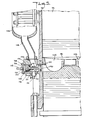
- a gas supply tank 106 is mounted on the outside of the casing 30 and is connected via a gas supply conduit 108 and a gas supply valve 110 to the interior of the casing in the region of the cavities 104 formed in the upper surface of the anvil 46.
- the gas supply tank 106 has an inlet connector 112 connected to a gas supply line 113 through which a charge of compressed gas, such as air, is supplied from an external source (not shown).
- a pilot valve 114 which is connected via pilot conduits 116 and 118, respectively, to the tank 104 and to a pilot opening 120 in the gas supply valve 110.
- the pilot valve 114 is shown to be operated manually by means of a crank arm 122 and a pull cord 124, although automatic valve operating means may also be provided.
- a spring (not shown) is arranged to bias the crank arm 122 upwardly to the position shown in Fig. 3. In this position of the crank arm, the pilot valve 114 prevents flow of pressurized air from the tank 104 via the pilot lines 116 and 118 to the pilot port 120 of the gas supply valve 110.
- the pull cord 124 is pulled to move the crank arm 122 downwardly, the pilot valve 114 is opened and compressed air flows from the tank 104 and pilot lines 116 and 118 to the pilot port 120 of the gas supply valve 110 to actuate the valve.
- actuation of the gas supply valve 110 permits a sudden burst of high pressure air from the tank 106 to enter into the region under the ram 32 to drive it upwardly in the casing 30.
- the flow of air from the tank 106 to the region under the ram 32 continues until the bottom of the ram clears the exhaust port 83, at which time the pull cord 124 is released to allow the pilot valve 114 and consequently the gas supply valve 110 to close.
- the ram 32 continues its upward movement in the casing 30 while compressing the air above it. Eventually the upward ram momentum is dissipated and converted to compression of the air in the bounce chamber 72 as well as to potential energy of the ram in the upper region of the casing. The ram then begins to fall in the casing; and after its lower portion passes by the inlet and exhaust ports 82 and 83, the air under the ram becomes trapped inside the casing 30 and becomes compressed and brought to a high temperature. When the ram nears the anvil, diesel fuel is injected into the cavities 104 in the upper portion of the anvil 46 to mix with the hot compressed air and to produce an explosion which drives the ram back up in the casing.
- the pull cord 124 may be pulled again to supply a fresh burst of compressed air into the region under the ram to drive it upwardly in the casing as described above. Once a proper explosion is achieved, the gas supply valve 110 remains closed and the hammer continues to operate in the normal manner.
- the valve 110 comprises a valve block 126 which is secured by means of bolts 128 (Fig. 7) to the hammer casing 30.
- the block 126 is formed with a large diameter central passageway 130 extending toward the casing 30.
- the casing 30 and the anvil 46 are also formed with a passageway 132 which communicate between the anvil cavities 104 and the passageway 130 formed in the valve block 126.
- the valve block 126 is also formed with a large diameter inlet passageway 134 which communicates from the upper surface of the block to the central passageway 130.
- the gas supply conduit 108 is mounted to extend from the inlet passageway 134 to the interior of the gas supply tank 106.
- a drain valve 131 is mounted in the bottom of the valve block 126 in communication with the central passageway 130 to drain any moisture which has formed in the tank 106.
- the valve block 126 has a forward portion 136 which projects into the passageway 132 in the casing 30. the forward end of the portion 136 is fitted with a valve seat 138 of hardened material and a poppet valve 140 rests on the seat 138.
- the seat 138 and valve 140 may be of the same construction as the poppet valves found in most internal combustion engines.
- the poppet valve 140 has a stem 142 which extends back through the central passageway 130 of the valve block 126.
- the stem 142 is connected at its rearward end to a piston 144 which is fitted closely inside a sleeve 146 in the rearward portion of the valve block.
- the piston 144 is provided with rings 148 to form a gas tight but sliding fit with the sleeve 146.
- the area of the forward face of the piston 144, i.e. the surface facing the valve 140 is somewhat larger than the valve so that pressure applied to the central passageway 130 produces a net force tending to pull the valve toward a closed position.
- the interior of the valve block 126 is formed with a spider-like support 150 located in the central passageway 130 just forwardly of the inlet passageway 134.
- the support 150 has a sleeve portion 152 to guide the valve stem 142 so that the valve will move axially in the passageway.
- the support is formed with large diameter openings 154 to permit gases to flow from the inlet passageway 134 forwardly to the valve 140.
- the valve 140 is further biased to a closed position seated on the valve seat 138 by means of a compression spring 156 with surrounds the valve stem 142 between the spider-like support 150 and a cushion assembly 158 which presses against the piston 144.
- the cushion assembly 158 comprises a sleeve 160 which closely fits over the valve stem 142 and which has a shoulder 162 to receive the end of the compression spring 156.
- the sleeve 160 has an enlarged rearward portion which presses against Belleville disc springs 164 resting on the piston 144.
- a cover plate 166 is bolted by means of bolts 168 to the valve block 126 to cover the rear face of the piston 144.
- the pilot line 118 is connected via the cover plate 166 to the passageway 130 behind the piston 144.
- the area of the front side of the piston 144 i.e. facing the valve 140
- the pressure applied via the passageway 108 to the region between the piston and the valve will produce a net force on the piston/valve assembly in the rearward direction, tending to hold the valve closed.
- the pilot valve 114 is opened, high pressure is applied via the pilot line 118 to the rear face of the piston 144 and the resulting net force on the piston/valve assembly is then in the forward direction, causing the valve to open.
- the gas supply valve is normally closed, with the compression spring 156 forcing the piston 144 rearwar.dly in the passageway 130; and the piston in turn pulls the valve 140 to a sealed position resting on the valve seat 138.
- the rear surface of the poppet valve 140 is directly exposed to the high pressure air from the tank 106, this pressure does not force the valve open because the same pressure acts in the opposite direction on the forward face of the piston 144, and because of the greater area of the forward face of the piston this high pressure ensures that the valve will remain closed.
- the valve 110 is opened by opening the pilot valve 114 and permitting compressed air to flow via the pilot line 118 to the rearward side of the piston 144. As explained above, this causes an unbalance of forces on the piston/valve assembly which in turn moves forwardly and opens the poppet valve 140. Compressed air then flows directly from behind the poppet valve through the passageway 132 and into the anvil cavities 102 to drive the piston 32 upwardly.
- the amount by which the poppet valve 140 can open is . limited by the permissible forward movement of the sleeve 160.
- the piston 144 moves forwardly it pushes the sleeve 160 ahead of it until, as seen in Fig. 8, the forward end of the sleeve contacts the sleeve portion 152 of the spider-like support 150.
- the opening movement is quite rapid and a sudden shock is produced when the sleeve 160 hits against the sleeve portion 152 of the support 150.
- This shock is cushioned by the Belleville disc springs 164 which permit a slight amount of continued forward movement of the valve and piston after the sleeve 160 hits against the sleeve portion 152.
- valves 110 and 114 The operation of the valves 110 and 114 can be seen from the schematic drawings of Figs. 10 and 11.
- the pilot valve 114 is biased by a spring 170 to a position preventing pressurized gas flow via the pilot lines 116 and 118 to the pilot inlet of the valve 110 and the valve 110 remains in its closed condition.
- the pull cord 124 is pulled and the crank arm 122 forces the valve 114 to its actuated condition as shown in Fig. 11, it permits pressurized gas to flow via the pilot lines 116 and 118 to the pilot port 120 of the gas supply valve 110.
- This flow of gas causes the piston 144 and the poppet valve 140 to move forwardly so that the poppet valve opens to admit compressed air directly into the hammer casing.
- the spring 170 returns it to the condition shown in Fig. 11 and the air trapped behind the piston 144 is allowed to vent to the atmosphere and the high pressure air applied via the inlet passageway 134, as well as the force of the compression spring 156, causes the valve to close.
- the invention may of course be used to provide compressed gas starting for diesel hammers of various sizes and it will be readily apparent to those skilled in the art how the various components should be sized.
- the invention is used to provide compressed air starting for an ICE No. 520 Diesel Powered hammer. These hammers have a ram which weighs about 5,000 lbs. (2,268 kilograms).
- the compressed air should provide approximately 15,000 foot pounds (20,340 joules) of energy to the ram 32, i.e. sufficient energy to raise the ram to a level of about 30 inches (76 cm.) above the anvil.
- This provides the ram with about 12,500 foot-pounds (16,950 joules) of potential energy due to ram height above the anvil plus about 2,500 foot-pounds (3,390 joules) of energy stored in the compressed air in ,the bounce chamber 72.
- the gas supply tank By providing the gas supply tank with an interior volume of about 2.67 cubic feet (0.076 cubic meters) and by charging the tank to about 250 pounds per square inch (17.2 bar) sufficient energy is available to generate a starting stroke as described above.
- a compressed gas reservoir (not shown) is provided. It has been found that if the reservoir has a total volume of fifteen cubic feet (0.425 cubic meters), then by supplying the reservoir from a thirty cubic feet (0.85 cubic meter) per minute compressor at two hundred fifty pounds per square inch (17.2 bar), the receiver can recharge the tank 106 at a rate which will permit the starting operation to be repeated four successive times at intervals of about fifteen seconds.
- the gas supply line 108, the valve passageways 130 and 134, the poppet valve 140 and the casing and anvil passageway 132 should each have a diameter of about 2 inches (5.1 cm.).
- the present invention in addition to providing pressurized gas starting for a diesel hammer as described above, may also provide the additional feature of converting a diesel hammer to bumpout operation in accordance with copending patent application Serial No. 405,615.
- the hammer For bumpout operation the hammer is provided as shown in Fig. 1, with an upper anvil 180 in the upper end of the casing 30. Also, removable plugs 182 are provided in the bounce chamber 72. In bumpout operation no diesel fuel is supplied to the hammer. Instead, pressurized gas is admitted to the underside of the ram 32 to drive it upwardly in the casing 30 until it strikes the upper anvil 180. By removing the plugs 182 the region above the ram is vented to permit the ram to move upwardly in the casing without compression of the air above it. By applying gas of sufficient pressure under the ram, it may be driven up high enough to impact against the upper anvil 180 to produce an uplift blow.
- covers are installed over the intake and exhaust ports 82 and 83 so that a continuous upward force can be applied to the ram and so that the subsequent fall of the ram will be cushioned.
- the casing 30 does not have to be provided with slots and other openings as are required for mechanical type ram lifting devices. Consequently, the hammer is better adapted to use for bumpout operation than prior hammers because no special sealing and casing reinforcement structures are needed other than the intake and exhaust closure plates described above.
- the intake or exhaust plate can be provided with a vent opening which will allow a controlled outflow of air from under the ram. It has been found that such vent opening, which has a diameter of about 1/2 inch (1.27 cm.) does not appreciably affect the ability of the applied pressurized gas to drive the ram up to the top of the casing.
Landscapes
- Engineering & Computer Science (AREA)
- General Engineering & Computer Science (AREA)
- Mining & Mineral Resources (AREA)
- Life Sciences & Earth Sciences (AREA)
- Paleontology (AREA)
- Civil Engineering (AREA)
- General Life Sciences & Earth Sciences (AREA)
- Structural Engineering (AREA)
- Chemical & Material Sciences (AREA)
- Combustion & Propulsion (AREA)
- Mechanical Engineering (AREA)
- Placing Or Removing Of Piles Or Sheet Piles, Or Accessories Thereof (AREA)
- Portable Nailing Machines And Staplers (AREA)
Applications Claiming Priority (2)
| Application Number | Priority Date | Filing Date | Title |
|---|---|---|---|
| US489572 | 1983-04-28 | ||
| US06/489,572 US4580641A (en) | 1983-04-28 | 1983-04-28 | Method and apparatus for starting diesel type hammers |
Publications (2)
| Publication Number | Publication Date |
|---|---|
| EP0123808A2 true EP0123808A2 (de) | 1984-11-07 |
| EP0123808A3 EP0123808A3 (de) | 1986-05-14 |
Family
ID=23944398
Family Applications (1)
| Application Number | Title | Priority Date | Filing Date |
|---|---|---|---|
| EP84101787A Withdrawn EP0123808A3 (de) | 1983-04-28 | 1984-02-21 | Verfahren und Vorrichtung zum Starten von Dieselrammbären |
Country Status (2)
| Country | Link |
|---|---|
| US (1) | US4580641A (de) |
| EP (1) | EP0123808A3 (de) |
Families Citing this family (10)
| Publication number | Priority date | Publication date | Assignee | Title |
|---|---|---|---|---|
| DE19529538A1 (de) * | 1995-08-11 | 1997-02-13 | Delmag Maschinenfabrik | Ramme |
| DE102004062043A1 (de) * | 2004-12-23 | 2006-07-13 | Delmag Gmbh & Co. Kg | Dieselhammer |
| NL1033528C2 (nl) * | 2007-03-09 | 2008-09-10 | Univ Eindhoven Tech | Hei-inrichting met dubbele ontbranding en werkwijze voor het werken met een dergelijke hei-inrichting. |
| KR101326161B1 (ko) * | 2012-05-16 | 2013-11-06 | 우주기계 주식회사 | 말뚝타격장치 |
| NL2011166C2 (nl) * | 2013-07-15 | 2015-01-21 | Fistuca B V | Hei-inrichting en werkwijze voor de toepassing daarvan. |
| EP2871287B1 (de) * | 2013-11-12 | 2016-06-08 | Delmag GmbH & Co. KG | Dieselramme |
| EP2871286B1 (de) | 2013-11-12 | 2016-03-23 | Delmag GmbH & Co. KG | Rammhammer |
| EP2924170A1 (de) * | 2014-03-28 | 2015-09-30 | Delmag GmbH & Co. KG | Rammhammer |
| EP2924171B1 (de) * | 2014-03-28 | 2016-07-13 | Delmag GmbH & Co. KG | Rammhammer |
| CN115030213B (zh) * | 2022-05-26 | 2023-04-11 | 上海勘测设计研究院有限公司 | 一种适用于海上风电基桩的工装以及应用方法 |
Family Cites Families (23)
| Publication number | Priority date | Publication date | Assignee | Title |
|---|---|---|---|---|
| US28151A (en) * | 1860-05-08 | Rice and clover hummer | ||
| US1102652A (en) * | 1912-08-14 | 1914-07-07 | Alexander Gibb | Driving and extracting piles, posts, and the like. |
| US1292429A (en) * | 1917-06-19 | 1919-01-28 | Richard Henry Annison | Pile-extracting, pile-driving, and like machine. |
| CH178644A (de) * | 1934-07-09 | 1935-07-31 | Knorr Bremse Ag | Verfahren zum Betrieb von Brennkraftmaschinen, die ein Werkzeug antreiben, und Einrichtung zur Durchführung des Verfahrens. |
| US2804856A (en) * | 1954-12-22 | 1957-09-03 | Syntron Co | Diesel hammer starting device |
| US2951345A (en) * | 1955-08-30 | 1960-09-06 | Delmag Maschinenfabrik | Pile and plank pulling device with diesel ram or the like |
| DE1112461B (de) * | 1958-05-12 | 1961-08-03 | Delmag Maschinenfabrik | Pfahlzieher |
| US3283832A (en) * | 1962-12-10 | 1966-11-08 | Raymond Int Inc | Hydraulic hammer |
| US3511325A (en) * | 1967-11-15 | 1970-05-12 | Tracto Technik | Device for extracting piles or the like |
| US3474870A (en) * | 1967-12-18 | 1969-10-28 | Paul M Cook | Tube driving apparatus |
| US3626918A (en) * | 1969-07-18 | 1971-12-14 | Trw Inc | Starting system for diesel engines |
| US3583499A (en) * | 1969-09-08 | 1971-06-08 | Hugo Cordes | Hydraulic pile extractor |
| US3667442A (en) * | 1970-02-16 | 1972-06-06 | White Sales Corp Graham | Pneumatic starting system for diesel engines |
| USRE28151E (en) | 1971-10-26 | 1974-09-10 | Tube driving apparatus | |
| US3815373A (en) * | 1972-06-07 | 1974-06-11 | D Giroux | Piling clamp |
| US3920083A (en) * | 1974-05-03 | 1975-11-18 | Toyoda Kikai Kogyo Kk | Pile driving and drawing apparatus |
| US4007803A (en) * | 1976-01-19 | 1977-02-15 | Atlantic Richfield Company | Expanding detonation chamber multi-shot gas exploder |
| DE2632015A1 (de) * | 1976-07-16 | 1978-01-19 | Motoren Turbinen Union | Dieselbrennkraftmaschine |
| GB1566984A (en) * | 1977-05-04 | 1980-05-08 | Nippon Kokan Kk | Method and an apparatus of driving and extracting an article by strain energy |
| US4131164A (en) * | 1977-11-23 | 1978-12-26 | Chambersburg Engineering Company | Adaptive valve control system for an impact device |
| SE421082B (sv) * | 1978-04-11 | 1981-11-23 | Nordstjernan Rederi Ab | Anordning vid pneumatiska startventiler for dieselmotorer |
| CH644935A5 (en) * | 1979-11-12 | 1984-08-31 | Nova Werke Ag | Compressed air starter for piston engines |
| NL8003510A (nl) * | 1980-03-24 | 1981-10-16 | Int Technische Handelsondernem | Dieselhamer en werkwijze voor het bedrijven ervan. |
-
1983
- 1983-04-28 US US06/489,572 patent/US4580641A/en not_active Expired - Fee Related
-
1984
- 1984-02-21 EP EP84101787A patent/EP0123808A3/de not_active Withdrawn
Also Published As
| Publication number | Publication date |
|---|---|
| EP0123808A3 (de) | 1986-05-14 |
| US4580641A (en) | 1986-04-08 |
Similar Documents
| Publication | Publication Date | Title |
|---|---|---|
| US5727639A (en) | Pile driving hammer improvement | |
| US3646598A (en) | Pile driver systems apparatus and method for driving a pile | |
| US4580641A (en) | Method and apparatus for starting diesel type hammers | |
| US4473123A (en) | Diesel hammer capable of delivering uplift blows and method of using same | |
| US8496072B2 (en) | Preloaded drop hammer for driving piles | |
| CA2338911C (en) | Underwater pile driving tool | |
| US4497376A (en) | Interchangeable ram diesel pile | |
| US3714789A (en) | Automatically self-regulating variable-stroke, variable-rate and quiet-operating pile driver method and system | |
| US4102408A (en) | Pile driving device | |
| US2948122A (en) | Combustible fuel operated pile driving hammers and the like | |
| US2093634A (en) | Diesel power hammer | |
| US3788402A (en) | Automatically self-regulating variable-stroke, variable-rate and quiet-operating pile driver apparatus | |
| CA1040103A (en) | Diesel pile hammer with vent for starting | |
| GB2067289A (en) | Seismic pulse generator | |
| CA1145961A (en) | Quiet bouncer pile driver method and apparatus with annular air storage chamber encircling & traveling with bouncing piston weight | |
| US4256187A (en) | Impact tool with hydraulic cocking mechanism | |
| US4523647A (en) | Power hammer | |
| US4770269A (en) | Closed air system seismic wave generator | |
| JPH0223687B2 (de) | ||
| CA1275320C (en) | Vent means for closed air system impact-type seismic source | |
| US4383582A (en) | Bouncer type pile driver | |
| US3356164A (en) | Pile driving mechanisms | |
| US3437157A (en) | Diesel pilehammer | |
| US4011886A (en) | Sleeve valve | |
| US4126191A (en) | Gas discharge type underwater hammer with liquid purge and reflood control |
Legal Events
| Date | Code | Title | Description |
|---|---|---|---|
| PUAI | Public reference made under article 153(3) epc to a published international application that has entered the european phase |
Free format text: ORIGINAL CODE: 0009012 |
|
| AK | Designated contracting states |
Designated state(s): DE GB NL |
|
| PUAL | Search report despatched |
Free format text: ORIGINAL CODE: 0009013 |
|
| AK | Designated contracting states |
Kind code of ref document: A3 Designated state(s): DE GB NL |
|
| STAA | Information on the status of an ep patent application or granted ep patent |
Free format text: STATUS: THE APPLICATION IS DEEMED TO BE WITHDRAWN |
|
| 18D | Application deemed to be withdrawn |
Effective date: 19870115 |
|
| RIN1 | Information on inventor provided before grant (corrected) |
Inventor name: HOLLAND, HENRY A. NELSON Inventor name: BANDURA, JAMES |