EP0124046A2 - Heizvorrichtung für das Einlasssystem einer Brennkraftmaschine, reagierend auf den Betriebszustand - Google Patents
Heizvorrichtung für das Einlasssystem einer Brennkraftmaschine, reagierend auf den Betriebszustand Download PDFInfo
- Publication number
- EP0124046A2 EP0124046A2 EP84104496A EP84104496A EP0124046A2 EP 0124046 A2 EP0124046 A2 EP 0124046A2 EP 84104496 A EP84104496 A EP 84104496A EP 84104496 A EP84104496 A EP 84104496A EP 0124046 A2 EP0124046 A2 EP 0124046A2
- Authority
- EP
- European Patent Office
- Prior art keywords
- engine
- coolant
- jacket
- internal combustion
- combustion engine
- Prior art date
- Legal status (The legal status is an assumption and is not a legal conclusion. Google has not performed a legal analysis and makes no representation as to the accuracy of the status listed.)
- Granted
Links
Images


Classifications
-
- F—MECHANICAL ENGINEERING; LIGHTING; HEATING; WEAPONS; BLASTING
- F01—MACHINES OR ENGINES IN GENERAL; ENGINE PLANTS IN GENERAL; STEAM ENGINES
- F01P—COOLING OF MACHINES OR ENGINES IN GENERAL; COOLING OF INTERNAL-COMBUSTION ENGINES
- F01P7/00—Controlling of coolant flow
- F01P7/14—Controlling of coolant flow the coolant being liquid
-
- F—MECHANICAL ENGINEERING; LIGHTING; HEATING; WEAPONS; BLASTING
- F01—MACHINES OR ENGINES IN GENERAL; ENGINE PLANTS IN GENERAL; STEAM ENGINES
- F01P—COOLING OF MACHINES OR ENGINES IN GENERAL; COOLING OF INTERNAL-COMBUSTION ENGINES
- F01P3/00—Liquid cooling
- F01P3/22—Liquid cooling characterised by evaporation and condensation of coolant in closed cycles; characterised by the coolant reaching higher temperatures than normal atmospheric boiling-point
- F01P3/2285—Closed cycles with condenser and feed pump
-
- F—MECHANICAL ENGINEERING; LIGHTING; HEATING; WEAPONS; BLASTING
- F02—COMBUSTION ENGINES; HOT-GAS OR COMBUSTION-PRODUCT ENGINE PLANTS
- F02M—SUPPLYING COMBUSTION ENGINES IN GENERAL WITH COMBUSTIBLE MIXTURES OR CONSTITUENTS THEREOF
- F02M31/00—Apparatus for thermally treating combustion-air, fuel, or fuel-air mixture
- F02M31/02—Apparatus for thermally treating combustion-air, fuel, or fuel-air mixture for heating
- F02M31/04—Apparatus for thermally treating combustion-air, fuel, or fuel-air mixture for heating combustion-air or fuel-air mixture
- F02M31/10—Apparatus for thermally treating combustion-air, fuel, or fuel-air mixture for heating combustion-air or fuel-air mixture by hot liquids, e.g. lubricants or cooling water
- F02M31/107—Controlled or manual switching
-
- F—MECHANICAL ENGINEERING; LIGHTING; HEATING; WEAPONS; BLASTING
- F01—MACHINES OR ENGINES IN GENERAL; ENGINE PLANTS IN GENERAL; STEAM ENGINES
- F01P—COOLING OF MACHINES OR ENGINES IN GENERAL; COOLING OF INTERNAL-COMBUSTION ENGINES
- F01P2060/00—Cooling circuits using auxiliaries
- F01P2060/10—Fuel manifold
-
- Y—GENERAL TAGGING OF NEW TECHNOLOGICAL DEVELOPMENTS; GENERAL TAGGING OF CROSS-SECTIONAL TECHNOLOGIES SPANNING OVER SEVERAL SECTIONS OF THE IPC; TECHNICAL SUBJECTS COVERED BY FORMER USPC CROSS-REFERENCE ART COLLECTIONS [XRACs] AND DIGESTS
- Y02—TECHNOLOGIES OR APPLICATIONS FOR MITIGATION OR ADAPTATION AGAINST CLIMATE CHANGE
- Y02T—CLIMATE CHANGE MITIGATION TECHNOLOGIES RELATED TO TRANSPORTATION
- Y02T10/00—Road transport of goods or passengers
- Y02T10/10—Internal combustion engine [ICE] based vehicles
- Y02T10/12—Improving ICE efficiencies
Definitions
- the present invention relates generally to internal combustion engine and more specifically to an induction system heating arrangement which is load responsive.
- One well known method of heating an incomming charge (air or air-fuel mixture) flowing through the induction manifold toward the combustion chamber or chambers of the engine includes directing some of the engine exhaust gases into a heating chamber formed about a suitable portion of the manifold (usually the riser bottom) and controlling the temperature to which the manifold rises using a temperture responsive bimetallic strip to operate a flap or like arrangement which throttles the amount of exhaust gas circulated through the chamber.
- this arrangement has suffered from the drawback that the temperature of the exhaust gases, due to the heating of the incomming charge, tend to be insufficient during engine warm-up and/or low temperature operations, to promote adequate oxidation of noxious components (e.g. HC and CO) in purifying devices such as catalytic converters etc.
- the above object is fullfilled via an engine system in which the engine coolant is permitted to boil and the gaseous coolant used as a vehicle for removing heat from the engine, and wherein a heating jacket associated with the induction conduit of the engine is supplied with some of the gaseous coolant via a control valve during cold engine starts and during modes of engine operation wherein it is advantageous from the view point of fuel economy and the like to raise the temperature of the incomming fuel charge.
- the supply is terminated under other modes of operation to avoid heating the incomming charge and reducing charging efficiency.
- the present invention takes the form of an internal combustion engine having (a) a coolant jacket into which coolant is introduced in a liquid state and discharged in a gaseous form and (b) an induction system including an induction conduit leading to a combustion chamber of the engine and which features a heating jacket for heating the induction conduit, the jacket having an inlet port in fluid communication with the coolant jacket and an outlet port, a valve for controlling fluid communication between the inlet port and the coolant jacket, a control device responsive to operating condition of the engine for operating the valve in a manner to open the valve and allow gaseous coolant from the coolant jacket to enter the jacket and heat the conduit by releasing the latent heat of evaporation thereof, when the engine is in a predetermined mode or modes of operation.
- FIG. 1 shows schematically an engine system incorporating an embodiment of the present invention.
- an internal combustion engine 10 includes a cylinder block 12 on which a cylinder head 14 is detachably secured.
- the cylinder head and cylinder block include suitable cavities 15 - 18 which define a coolant jacket 20.
- the coolant is introduced into the coolant jacket 20 through a port 22 formed in the cylinder block 12.
- port 22 is arranged to communicate with a lower level of the coolant jacket 20.
- a radiator 26 Fluidly communicating with a vapor discharge port 24 of the cylinder head 12 is a radiator 26 (heat exchanger). Disposed in the vapor discharge port 24 is a separator 28 which in this embodiment takes the form of a mesh screen. The separator 28 serves to separate the droplets of liquid and/or foam which tend to be produced by the boiling action, from the vapor per se and minimize unecessary liquid loss from the coolant jacket.
- a electrically driven fan 30 Disposed in a coolant return conduit 32 is a return pump 34.
- the pump is driven by an electric motor 36.
- a level sensor 40 is disposed as shown. It will be noted that this sensor is located at a level higher than that of the combustion chambers, exhaust ports and valves (viz., structure subject to high heat flux) so as to maintain same securely immersed in coolant and therefore attenuate engine knocking and the like due to the formation of localized zones of abnormally high temperature or "hot spots".
- a temperature sensor 44 Located above the level sensor 40 so as to be exposed to the gaseous coolant is a temperature sensor 44 (alternatively a pressure sensor may be used).
- the output of the level sensor 40 and the temperature sensor 44 are fed to a control circuit 46 or modulator which is suitably connected with a source of EMF upon closure of a switch 48.
- This switch of course may advantageously be arranged to be simultaneously closed with the ignition switch of the engine (not shown).
- the control circuit 46 further receives an input from the engine distributor 50 indicative of engine speed and an input from a load sensing device 52 such as a throttle position sensor. It will be noted that as an alternative to throttle position, the output of an air flow meter or an induction vacuum sensor may used to indicate load.
- An induction manifold 100 is arranged to interconnect a carburetor 102 and the induction port or ports 104 of the engine 10.
- a heating jacket 106 is formed about the branch runner or runners 108 of the manifold as shown in Figs. 1 and 3.
- a control valve 110 is arranged to control an inlet port 112 of the heating jacket 106 via which fluid communication between the coolant jacket 20 formed in the cylinder head 14 and the heating jacket 106 is established. It will be noted that the level of the inlet port 112 is above that at which the level of liquid coolant is maintained by the level sensor 40 so as to ensure that gaseous coolant will be predominately fed into the heating jacket 106.
- a vertically extending conduit 114 is formed in the manifold 100 to lead the gasesous coolant from the inlet port 112 into the lower portion of the heating jacket 106.
- a drain port 116 is formed at a location distal from the inlet port 112. The drain port 116 fluidly communicates via conduit 117 with the return conduit 32 at a location upstream of the pump 34.
- a vacuum motor 120 is operatively connected with the control valve 110.
- the vacuum chamber 122 of this motor is arranged to be selectively connectable with either a source of vacuum (in this case the induction manifold 100 at a location downstream of the throttle valve or valves 124) or the ambient atmosphere via a three-way electromagnetic valve 126.
- the solenoid coil 128 of the three-way valve 126 is connected with the control circuit 46 in a manner to be energized to establish communication between the vacuum chamber 122 and the induction manifold 100 when the engine is operating under conditions which shall be termed "urban cruising" and de-energized to establish communication between the atmosphere and the chamber -when the engine is operating under relatively high load and high engine speed conditions. This control will become clear hereinlater.
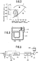
- Fig. 2 graphically shows in terms of engine torque and engine speed the various load "zones" which are encountered by an automotive vehicle engine.
- the curve F denotes full throttle tbrque characteristics
- trace L denotes the resistance encountered when a vehicle is running on a level surface
- zones I, II and III denote respectively "urban cruising", “high speed cruising” and “high load operation” (such as hillclimbing, towing etc.).
- Fig. 4 shows an example of circuitry which may be used to control the pump and the solenoid of the two-way valve.
- the distributor 48 of the engine ignition system is connected with the source of EMF (Fig. 1) via the switch 46.
- a monostable multivibrator 54 is connected in series between the distributor 48 and a smoothing circuit 56.
- a DC-DC converter 57 is arranged, as shown in broken line, to ensure a supply of constant voltage to the circuit as a whole.
- a voltage divider consisting of resistors R1 and R2 provides a comparator 58 with a reference voltage at one input thereof while the second input of said comparator receives the output of the smoothing circuit 56.
- a second voltage dividing arrangement consisting of a resistor R3 and a thermistor (viz., the temperature sensor 44) applies a reference voltage to a second comparator 60 which also receives a signal from a cam operated throttle switch 62 via a resistor arrangement including resistors R4, R5, R6 and R7 connected as shown.
- the output of the comparator 60 is applied to the fan for energizing same.
- the circuit further includes a transistor 80 which acts a switch upon receiving an output from the level sensor 40 to establish a circuit between the source of EMF and ground.
- a transistor 80 which acts a switch upon receiving an output from the level sensor 40 to establish a circuit between the source of EMF and ground.
- an inverter or the like may be interposed between the level sensor 40 and the transistor 80, and the level sensor adapted to produce an output when immersed in coolant. With this arrangement should the level sensor malfunction, the lack of output therefrom would cause the transistor 80 to be rendered conductive and the pump 36 energized to overfill the coolant jacket.
- a NAND gate 82 is arranged to receive the outputs of the comparator 58 and the throttle valve switch 62 and to, upon both of the inputs assuming a low level (indicating that the engine is operating at an engine speed and load lower than the levels whereat the comparator outputs a high level and the switch 62 is closed) to render transistor 84 conductive in a manner to energize solenoid coil 128 and open the control valve 110.
- Fig. 5 shows an alternate circuit arrangement which may be used to control the two-way valve 126.
- This alternative arrangement includes a transistor 70, a clock circuit 72, a ripple counter 74, a smoothing circuit 76, and an inverter 86, all connected as shown. Due to the fact that the frequency of injection control pulses varies with engine speed and the voltage output of the smoothing circuit varies with pulse width as well as the frequency of injection, it is possible to use this arrangement in place of both of the throttle switch 62 and distributor 50 as will be appreciated by those skilled in the art.
- the output of the smoothing circuit may be applied to the base of the transistor 84 via inverter 86 to acheive the desired control.
- the instant invention finds particular application in Diesel engines wherein, by heating the incomming flow of air during cold engine starts and/or low engine temperature operation, the characteristic noise of such engines is remarkably reduced.
- the reason for this improvement is due to the fact that the temperature of the charge at the final stage of the compression phase (prior spontaneous or self ignition) T 2 is given by the following equation: wherein:
Landscapes
- Engineering & Computer Science (AREA)
- Chemical & Material Sciences (AREA)
- Combustion & Propulsion (AREA)
- Mechanical Engineering (AREA)
- General Engineering & Computer Science (AREA)
- Output Control And Ontrol Of Special Type Engine (AREA)
- Combustion Methods Of Internal-Combustion Engines (AREA)
Applications Claiming Priority (2)
| Application Number | Priority Date | Filing Date | Title |
|---|---|---|---|
| JP73001/83 | 1983-04-27 | ||
| JP58073001A JPS59200051A (ja) | 1983-04-27 | 1983-04-27 | 自動車用エンジンの吸気加熱装置 |
Publications (3)
| Publication Number | Publication Date |
|---|---|
| EP0124046A2 true EP0124046A2 (de) | 1984-11-07 |
| EP0124046A3 EP0124046A3 (en) | 1986-01-29 |
| EP0124046B1 EP0124046B1 (de) | 1988-01-27 |
Family
ID=13505678
Family Applications (1)
| Application Number | Title | Priority Date | Filing Date |
|---|---|---|---|
| EP84104496A Expired EP0124046B1 (de) | 1983-04-27 | 1984-04-19 | Heizvorrichtung für das Einlasssystem einer Brennkraftmaschine, reagierend auf den Betriebszustand |
Country Status (4)
| Country | Link |
|---|---|
| US (1) | US4548183A (de) |
| EP (1) | EP0124046B1 (de) |
| JP (1) | JPS59200051A (de) |
| DE (1) | DE3469050D1 (de) |
Cited By (2)
| Publication number | Priority date | Publication date | Assignee | Title |
|---|---|---|---|---|
| US4616601A (en) * | 1984-07-16 | 1986-10-14 | Nissan Motor Co., Ltd. | Radiator anti-freeze arrangement for evaporative type cooling system |
| WO1990000226A1 (en) * | 1988-07-01 | 1990-01-11 | Robert Bosch Gmbh | Motor fuel supply system |
Families Citing this family (10)
| Publication number | Priority date | Publication date | Assignee | Title |
|---|---|---|---|---|
| US4768493A (en) * | 1984-04-27 | 1988-09-06 | Honda Giken Kogyo Kabushiki Kaisha | Blow-by gas heating system for internal combustion engines |
| JPS6183424A (ja) * | 1984-09-29 | 1986-04-28 | Nissan Motor Co Ltd | 内燃機関の沸騰冷却装置におけるポンプ異常対策装置 |
| JPS6183405A (ja) * | 1984-09-29 | 1986-04-28 | Nissan Motor Co Ltd | 潤滑油冷却装置 |
| EP0189881B1 (de) * | 1985-01-28 | 1991-04-03 | Nissan Motor Co., Ltd. | Kühlvorrichtung einer Kraftfahrzeugmaschine |
| US4662316A (en) * | 1986-01-29 | 1987-05-05 | Nissan Motor Co., Ltd. | Cooling system for automotive engine or the like |
| US4669426A (en) * | 1986-01-29 | 1987-06-02 | Nissan Motor Co., Ltd. | Cooling system for automotive engine or the like |
| US5680839A (en) * | 1996-07-08 | 1997-10-28 | J. C. Moore Research, Inc. | Apparatus and method of delivering a fuel and air mixture for internal combustion engines |
| US8037872B2 (en) | 2007-05-31 | 2011-10-18 | Caterpillar Inc. | Engine system having cooled and heated inlet air |
| RU2374462C1 (ru) * | 2008-05-21 | 2009-11-27 | Государственное образовательное учреждение высшего профессионального образования Саратовский государственный технический университет | Система охлаждения двигателя внутреннего сгорания |
| KR101795279B1 (ko) | 2016-06-22 | 2017-11-08 | 현대자동차주식회사 | 내연기관의 분리냉각 시스템 |
Family Cites Families (17)
| Publication number | Priority date | Publication date | Assignee | Title |
|---|---|---|---|---|
| US1339403A (en) * | 1917-09-10 | 1920-05-11 | John H Lytle | Carbureter |
| GB197827A (en) * | 1922-05-02 | 1923-05-24 | Edward Dodson | Improvements in the heating of carburettors, vaporizers, and the like, as used on internal combustion engines |
| DE450157C (de) * | 1925-10-02 | 1927-09-29 | Arthur Kuehl | Spritzvergaser |
| US1822147A (en) * | 1926-05-19 | 1931-09-08 | Waukesha Motor Co | Intake mixture heating system |
| US1736003A (en) * | 1927-01-03 | 1929-11-19 | Mccord Radiator & Mfg Co | Steam-heated fuel intake for internal-combustion engines |
| US1787562A (en) * | 1929-01-10 | 1931-01-06 | Lester P Barlow | Engine-cooling system |
| US2420436A (en) * | 1946-02-06 | 1947-05-13 | Mallory Marion | Temperature control for internalcombustion engines |
| US3385940A (en) * | 1966-10-21 | 1968-05-28 | Roper John | Thermal switch |
| US3714933A (en) * | 1970-11-16 | 1973-02-06 | Honda Motor Co Ltd | Automatic temperature control device for intake air of an internal combustion engine |
| US3832985A (en) * | 1971-06-11 | 1974-09-03 | R Edde | Non-pollution carburetion system for engines |
| JPS5218846B2 (de) * | 1973-01-29 | 1977-05-24 | ||
| BE819559A (nl) * | 1973-09-11 | 1975-03-05 | Inrichting voor het verdampen van vloeibare brandstof | |
| JPS5540367Y2 (de) * | 1975-11-19 | 1980-09-20 | ||
| JPS569636A (en) * | 1979-07-02 | 1981-01-31 | Nissan Motor Co Ltd | Temperature controller for internal combustion engine |
| JPS5632071A (en) * | 1979-08-23 | 1981-04-01 | Nissan Motor Co Ltd | Intake air heating system for internal combustion engine |
| US4452215A (en) * | 1981-11-16 | 1984-06-05 | Ennco Inc. | Fuel system for internal combustion engines |
| JPS58165560A (ja) * | 1982-03-26 | 1983-09-30 | Nissan Motor Co Ltd | デイ−ゼルエンジンの振動低減装置 |
-
1983
- 1983-04-27 JP JP58073001A patent/JPS59200051A/ja active Pending
-
1984
- 1984-04-19 DE DE8484104496T patent/DE3469050D1/de not_active Expired
- 1984-04-19 EP EP84104496A patent/EP0124046B1/de not_active Expired
- 1984-04-20 US US06/602,448 patent/US4548183A/en not_active Expired - Fee Related
Cited By (2)
| Publication number | Priority date | Publication date | Assignee | Title |
|---|---|---|---|---|
| US4616601A (en) * | 1984-07-16 | 1986-10-14 | Nissan Motor Co., Ltd. | Radiator anti-freeze arrangement for evaporative type cooling system |
| WO1990000226A1 (en) * | 1988-07-01 | 1990-01-11 | Robert Bosch Gmbh | Motor fuel supply system |
Also Published As
| Publication number | Publication date |
|---|---|
| DE3469050D1 (en) | 1988-03-03 |
| EP0124046A3 (en) | 1986-01-29 |
| JPS59200051A (ja) | 1984-11-13 |
| EP0124046B1 (de) | 1988-01-27 |
| US4548183A (en) | 1985-10-22 |
Similar Documents
| Publication | Publication Date | Title |
|---|---|---|
| US4258676A (en) | Heating system producing warm air for motor vehicles driven by an internal combustion engine | |
| US5337704A (en) | Engine cooling system with thermostat coolant flow control between head and block | |
| KR0165839B1 (ko) | 배기 가스 방출 제어 방법 및 시스템 | |
| US4548183A (en) | Operational mode responsive heating arrangement for internal combustion engine induction system | |
| US6681725B2 (en) | Internal combustion engine with regenerator | |
| US4567858A (en) | Load responsive temperature control arrangement for internal combustion engine | |
| EP0121181B1 (de) | Lastabhängige Temperaturregelvorrichtung für Brennkraftmaschine | |
| JP3379354B2 (ja) | 2系統冷却装置付き内燃機関の排気再循環制御装置 | |
| US6273033B1 (en) | Internal combustion engine installation in a motor vehicle | |
| JP4062285B2 (ja) | 蓄熱システム | |
| EP0548174B1 (de) | Kühlanlage für motoren | |
| US5435277A (en) | Hot water injection apparatus for water cooling engine | |
| US4391407A (en) | Vehicle cabin heater | |
| US5941220A (en) | Motor vehicle with an internal combustion engine with an external exhaust gas recirculation system and heater | |
| US20070170271A1 (en) | Auxiliary power unit heating system | |
| JPH0814042A (ja) | 動力車両用液冷式内燃機関の冷却装置 | |
| JPS64573B2 (de) | ||
| KR19980038640A (ko) | 강제 순환식 수냉 엔진의 냉각장치 | |
| JPS6042187Y2 (ja) | 内燃機関の冷却装置 | |
| SU853128A1 (ru) | Система охлаждени дизел | |
| JPH022896Y2 (de) | ||
| KR100244746B1 (ko) | 엔진 냉각시 웜업시간 단축을 위한 냉각수 순환제어장치 | |
| RU2049922C1 (ru) | Система жидкостного охлаждения двигателя внутреннего сгорания с наддувом | |
| JPS6344930B2 (de) | ||
| SU1444176A1 (ru) | Устройство дл обогрева кабины и двигател внутреннего сгорани транспортного средства |
Legal Events
| Date | Code | Title | Description |
|---|---|---|---|
| PUAI | Public reference made under article 153(3) epc to a published international application that has entered the european phase |
Free format text: ORIGINAL CODE: 0009012 |
|
| 17P | Request for examination filed |
Effective date: 19840419 |
|
| AK | Designated contracting states |
Designated state(s): DE FR GB |
|
| RAP1 | Party data changed (applicant data changed or rights of an application transferred) |
Owner name: NISSAN MOTOR CO., LTD. |
|
| PUAL | Search report despatched |
Free format text: ORIGINAL CODE: 0009013 |
|
| AK | Designated contracting states |
Designated state(s): DE FR GB |
|
| 17Q | First examination report despatched |
Effective date: 19860825 |
|
| GRAA | (expected) grant |
Free format text: ORIGINAL CODE: 0009210 |
|
| AK | Designated contracting states |
Kind code of ref document: B1 Designated state(s): DE FR GB |
|
| REF | Corresponds to: |
Ref document number: 3469050 Country of ref document: DE Date of ref document: 19880303 |
|
| ET | Fr: translation filed | ||
| PLBE | No opposition filed within time limit |
Free format text: ORIGINAL CODE: 0009261 |
|
| STAA | Information on the status of an ep patent application or granted ep patent |
Free format text: STATUS: NO OPPOSITION FILED WITHIN TIME LIMIT |
|
| 26N | No opposition filed | ||
| PGFP | Annual fee paid to national office [announced via postgrant information from national office to epo] |
Ref country code: GB Payment date: 19910325 Year of fee payment: 8 |
|
| PGFP | Annual fee paid to national office [announced via postgrant information from national office to epo] |
Ref country code: FR Payment date: 19910409 Year of fee payment: 8 |
|
| PGFP | Annual fee paid to national office [announced via postgrant information from national office to epo] |
Ref country code: DE Payment date: 19910531 Year of fee payment: 8 |
|
| PG25 | Lapsed in a contracting state [announced via postgrant information from national office to epo] |
Ref country code: GB Effective date: 19920419 |
|
| GBPC | Gb: european patent ceased through non-payment of renewal fee | ||
| PG25 | Lapsed in a contracting state [announced via postgrant information from national office to epo] |
Ref country code: FR Effective date: 19921230 |
|
| PG25 | Lapsed in a contracting state [announced via postgrant information from national office to epo] |
Ref country code: DE Effective date: 19930101 |
|
| REG | Reference to a national code |
Ref country code: FR Ref legal event code: ST |