EP0124391A1 - Die Fugen zwischen den Elementen eines Gitters aus Kunststoff zur Verwendung bei der Herstellung von Bodenbelägen - Google Patents
Die Fugen zwischen den Elementen eines Gitters aus Kunststoff zur Verwendung bei der Herstellung von Bodenbelägen Download PDFInfo
- Publication number
- EP0124391A1 EP0124391A1 EP84400592A EP84400592A EP0124391A1 EP 0124391 A1 EP0124391 A1 EP 0124391A1 EP 84400592 A EP84400592 A EP 84400592A EP 84400592 A EP84400592 A EP 84400592A EP 0124391 A1 EP0124391 A1 EP 0124391A1
- Authority
- EP
- European Patent Office
- Prior art keywords
- joints
- rules
- fractioning
- grating according
- grating
- Prior art date
- Legal status (The legal status is an assumption and is not a legal conclusion. Google has not performed a legal analysis and makes no representation as to the accuracy of the status listed.)
- Ceased
Links
- 239000004033 plastic Substances 0.000 title claims description 5
- 239000000463 material Substances 0.000 title claims description 3
- 238000010276 construction Methods 0.000 title abstract 2
- 239000004570 mortar (masonry) Substances 0.000 claims abstract description 13
- 239000011248 coating agent Substances 0.000 claims abstract description 11
- 238000000576 coating method Methods 0.000 claims abstract description 11
- 239000003000 extruded plastic Substances 0.000 claims abstract description 5
- 239000004576 sand Substances 0.000 claims abstract description 4
- 238000004873 anchoring Methods 0.000 claims description 6
- 229910003460 diamond Inorganic materials 0.000 claims description 3
- 239000010432 diamond Substances 0.000 claims description 3
- 238000005192 partition Methods 0.000 claims description 3
- 238000007789 sealing Methods 0.000 claims description 2
- 238000011065 in-situ storage Methods 0.000 abstract 1
- 238000000034 method Methods 0.000 description 6
- 239000011083 cement mortar Substances 0.000 description 3
- 238000005194 fractionation Methods 0.000 description 3
- 238000009415 formwork Methods 0.000 description 2
- XLYOFNOQVPJJNP-UHFFFAOYSA-N water Substances O XLYOFNOQVPJJNP-UHFFFAOYSA-N 0.000 description 2
- 238000004078 waterproofing Methods 0.000 description 2
- 230000006978 adaptation Effects 0.000 description 1
- 230000004069 differentiation Effects 0.000 description 1
- 238000001125 extrusion Methods 0.000 description 1
- 238000009434 installation Methods 0.000 description 1
- 239000011150 reinforced concrete Substances 0.000 description 1
- 238000010079 rubber tapping Methods 0.000 description 1
- 238000000926 separation method Methods 0.000 description 1
- 239000007787 solid Substances 0.000 description 1
- 238000012795 verification Methods 0.000 description 1
Images


Classifications
-
- E—FIXED CONSTRUCTIONS
- E04—BUILDING
- E04D—ROOF COVERINGS; SKY-LIGHTS; GUTTERS; ROOF-WORKING TOOLS
- E04D11/00—Roof covering, as far as not restricted to features covered by only one of groups E04D1/00 - E04D9/00; Roof covering in ways not provided for by groups E04D1/00 - E04D9/00, e.g. built-up roofs, elevated load-supporting roof coverings
-
- E—FIXED CONSTRUCTIONS
- E04—BUILDING
- E04D—ROOF COVERINGS; SKY-LIGHTS; GUTTERS; ROOF-WORKING TOOLS
- E04D7/00—Roof covering exclusively consisting of sealing masses applied in situ; Gravelling of flat roofs
Definitions
- the present invention relates to a grating forming the joints between paving elements.
- this grating is applicable to the constitution of a circulation coating on the decoupling layer in sand for example, of a waterproofing coating of a support structure such as a terrace.
- a first technique consists in pouring a screed in cement mortar on the decoupling layer, the extent of which is divided by fractioning joints.
- the disadvantage of this continuous screed is that it is not removable and that it is not possible to avoid demolition by breakage of the screed as a whole when a disaster related to a leak product and a verification of the waterproof coating is required.
- a second technique consists in placing prefabricated slabs on the decoupling layer.
- the disadvantage of these slabs is that their handling is painful because of their weight and their bulk; in addition, multiple cutouts are required to cover any surface. Consequently, this circulation coating is not very economical.
- a third technique consists of placing plastic molds forming lost formwork on the separation layer and filling these molds on site with cement mortar.
- the disadvantage of these molds is that they are expensive and weigh heavily on the cost of the circulation coating.
- this technique has the advantage over the previous ones of allowing the disassembly of the slabs thus molded individually during a leakage search; moreover, the work is much less arduous and the adaptation to the shape of the surface to be covered is very easy.
- the present invention aims to improve the third technique, by remedying its drawbacks, retaining its advantages and revealing others.
- this grating makes it possible to form the joints in all cases and it is therefore usable, with most of the above advantages, when the paving elements, instead of being mortar slabs poured in place, are prefabricated mortar slabs, briquettes, tiles, pavers or others.
- the grating comprises hollow rules of extruded plastic material having a section with two perpendicular axes of symmetry, in particular in the shape of a diamond, to avoid favoring a direction of installation, the nodes of crossing of these rules being obtained by interlocking them previously notched at mid-height.
- the rules protrude, preferably when the paving elements are in mortar poured on site, on each of their longitudinal faces, two anchoring ribs inclined towards the two edges on which the considered face ends.
- each rule is in the form of an almost flat dihedral and are connected by at least one internal stiffening partition.
- these joints are constituted by tubular plastic profiles whose height is equal to that of the rules and consequently of paving elements, the longitudinal faces of these profiles being broken in the shape of re-entrant dihedrons.
- Each longitudinal face of the profiles forming fractioning joints is connected to the edges by beaked edges allowing the anchoring in the mortar and the attachment of the lateral ribs of a possible contiguous rule.
- tubular profiles forming fractioning joints cooperate, in the corners, with studs whose sides of their square section have a width equal to the thickness (E) of these profiles and whose height is equal to that of the latter.
- Each stud is made integral, by a sole in particular, with four screeds shaped for the interlocking of the tubular profiles forming fractioning joints.
- 1 designates a reinforced concrete terrace slab, 2 a low wall surrounding this terrace and 3 a rim with a drop of water protruding inside the low wall.
- the slab 1 and the wall 2 are covered by a sealing coating 4. on which is deposited a layer of decoupling 5, made of sand for example.
- the surface to be protected is divided by fractioning joints 6 into several base surfaces 7 (square or rectangular) in each of which are arranged gratings 8. These are constituted by rules 9, 10 identical to each other and crossing at a right angle in order to delimit elementary square spaces 11 having the volume of a slab. Cement mortar is then poured into these spaces in order to form, after setting, slabs 12 perfectly attached to the rules 9, 10 and to the fractioning joints 6.
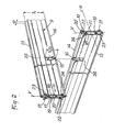
- each rule 9, 10 of a grating 8 is constituted by a hollow tubular profile in extruded plastic. Its section is symmetrical along two perpendicular axes of symmetry V and H; in the example shown, this section has the shape of a diamond; as soon as this condition is fulfilled, no precaution should be taken to machine and set a rule, because no differentiation appears between the top and the bottom, between the left side and the right side; it follows that the notching described in the following to be able to cross the rules ( Figure 2) can be performed from any edge 13, 14 of a rule and that to carry out interlocking, it suffices simply to present the rules 9 with their notches 15 open at the bottom and the rules 10, absolutely identical to the previous ones, with their notches -16 open at the top.
- each rule 9, 10 comprises two edges 13, 14 whose width "e” corresponds to that of the joint to be formed between the slabs 12, and two longitudinal walls 17, 18 shaped as relatively flat dihedrons projecting outwards, the height "h” of this rule being equal to the thickness of the slabs 12.
- the tubular profile constituting these rules being hollow, it is deformable in a relatively elastic manner, which allows it to compensate for the shrinkage of the mortar when it is taken after pouring the slabs, which also allows it to constitute an effective expansion joint intervening in a leaktight manner both during a rise and a lowering of the ambient temperature.
- the rules should not be too flexible; on the contrary, they must have a certain stiffness, a certain spring.
- the longitudinal walls 17, 18 are connected, in the example chosen, by two small internal partitions 19, 20 coming from extrusion.
- each rule must be well anchored in the mortar to perfectly follow the aforementioned dimensional variations, which are very small, moreover, of the slabs. Consequently, the longitudinal walls 17, 18 of each rule have protruding ribs 21 and 22, 23 and 24 inclined outward and the two edges 19 and 20 respectively.
- the notches 15, 16 are absolutely identical and machined at mid-height "h / 2" over a width corresponding substantially to the average thickness of the rules. Given the aforementioned symmetry that this tapping also respects, all the rules can be tapped at the same time without any respect for the direction of presentation; to make a crossing node, it suffices, as shown in Figure 2, to present the rules 10 with their notches 16 open at the top and perpendicular to the rules 9 with their notches 15 open at the bottom, putting these notches 15 and 16 facing each other, then bringing said rules together to fit into said entaitles, the solid parts 25 and 26 that these let exist.
- the aforementioned fractionation joints 6 are also constituted by tubular profiles made of extruded plastic, the height h of which is equal to that of the rules 9, 10 and therefore the thickness of the slabs 12.
- These tubular joints 6 have edges 27, 28 and longitudinal walls 29, 30 which are shaped as relatively flat dihedrons, returning inside said joints.
- the edges 27, 28 are connected to the walls 29, 30 by beaked edges 31 provided to ensure, in cooperation with the re-entrant conformation of said walls, effective anchoring in the mortar of the slabs; in addition, these edges are positioned so that the ribs 21 to 24 of the rules 9, 10 can hang there when it is necessary, due to the shape and the particular dimensions of the terrace, to place side by side a split joint and a ruler.
- Each joint crossing node 6 delimiting the base surfaces 7 makes use of a stud 32 illustrated in FIG. 4.
- This stud has a square section the sides of which have a width "1" equal to the thickness "E" of the joints so that the faces of the studs rigorously extend those of said joints further, the height h of this stud is equal to that of these joints, so that the top of the studs is flush with the visible face of the paving.
- Each stud 32 is made integral, by a sole 33 for example, of four orthogonal yokes 34 to 37 extending to limited height and intended to receive, for centering, the ends of the fractionation joints 6 which terminate there.
Landscapes
- Engineering & Computer Science (AREA)
- Architecture (AREA)
- Civil Engineering (AREA)
- Structural Engineering (AREA)
- Road Paving Structures (AREA)
- Forms Removed On Construction Sites Or Auxiliary Members Thereof (AREA)
Applications Claiming Priority (2)
| Application Number | Priority Date | Filing Date | Title |
|---|---|---|---|
| FR8304965 | 1983-03-25 | ||
| FR8304965A FR2543196A1 (de) | 1983-03-25 | 1983-03-25 |
Publications (1)
| Publication Number | Publication Date |
|---|---|
| EP0124391A1 true EP0124391A1 (de) | 1984-11-07 |
Family
ID=9287251
Family Applications (1)
| Application Number | Title | Priority Date | Filing Date |
|---|---|---|---|
| EP84400592A Ceased EP0124391A1 (de) | 1983-03-25 | 1984-03-23 | Die Fugen zwischen den Elementen eines Gitters aus Kunststoff zur Verwendung bei der Herstellung von Bodenbelägen |
Country Status (2)
| Country | Link |
|---|---|
| EP (1) | EP0124391A1 (de) |
| FR (1) | FR2543196A1 (de) |
Cited By (3)
| Publication number | Priority date | Publication date | Assignee | Title |
|---|---|---|---|---|
| DE102005007949A1 (de) * | 2004-08-03 | 2006-08-31 | Steinwerk Köstner OHG | Vorrichtung zum Verlegen von Platten |
| DE202012007429U1 (de) | 2012-08-01 | 2012-08-29 | Jan Nowak | Abstandhalter - Verbindungssystem insbesondere beim Verlegen von lose liegenden Fliesen und Platten |
| EP4707493A1 (de) * | 2024-09-10 | 2026-03-11 | Blok Design SL | Wiederverwendbares modulares system für ausstellungsstand |
Citations (8)
| Publication number | Priority date | Publication date | Assignee | Title |
|---|---|---|---|---|
| US1677760A (en) * | 1928-01-18 | 1928-07-17 | Galassi Pasquale | Dividing strip for terrazzo flooring |
| FR774338A (fr) * | 1933-07-14 | 1934-12-05 | Perfectionnements à la confection de terrasses, planchers, etc. | |
| US2025209A (en) * | 1934-02-10 | 1935-12-24 | James H Jacobson | Expansion and contraction joint |
| FR1305499A (fr) * | 1960-09-09 | 1963-01-30 | Profil pour joint de retrait, de dilatation ou de bétonnage | |
| DE6750174U (de) * | 1968-08-16 | 1969-01-02 | Gallo K G Fa | Fugenschiene |
| DE1784069A1 (de) * | 1968-07-04 | 1971-07-15 | Continental Gummi Werke Ag | Dehnfugendichtung |
| DE2541030A1 (de) * | 1975-09-15 | 1977-03-17 | Bour Max De | Lehre zur herstellung von dehnungsfugen in betonbelaegen |
| DE2609456A1 (de) * | 1976-03-08 | 1977-09-22 | Wagner Hans Juergen | Lehre zur herstellung von dehnungsfugen in betonbelaegen |
-
1983
- 1983-03-25 FR FR8304965A patent/FR2543196A1/fr active Pending
-
1984
- 1984-03-23 EP EP84400592A patent/EP0124391A1/de not_active Ceased
Patent Citations (8)
| Publication number | Priority date | Publication date | Assignee | Title |
|---|---|---|---|---|
| US1677760A (en) * | 1928-01-18 | 1928-07-17 | Galassi Pasquale | Dividing strip for terrazzo flooring |
| FR774338A (fr) * | 1933-07-14 | 1934-12-05 | Perfectionnements à la confection de terrasses, planchers, etc. | |
| US2025209A (en) * | 1934-02-10 | 1935-12-24 | James H Jacobson | Expansion and contraction joint |
| FR1305499A (fr) * | 1960-09-09 | 1963-01-30 | Profil pour joint de retrait, de dilatation ou de bétonnage | |
| DE1784069A1 (de) * | 1968-07-04 | 1971-07-15 | Continental Gummi Werke Ag | Dehnfugendichtung |
| DE6750174U (de) * | 1968-08-16 | 1969-01-02 | Gallo K G Fa | Fugenschiene |
| DE2541030A1 (de) * | 1975-09-15 | 1977-03-17 | Bour Max De | Lehre zur herstellung von dehnungsfugen in betonbelaegen |
| DE2609456A1 (de) * | 1976-03-08 | 1977-09-22 | Wagner Hans Juergen | Lehre zur herstellung von dehnungsfugen in betonbelaegen |
Cited By (4)
| Publication number | Priority date | Publication date | Assignee | Title |
|---|---|---|---|---|
| DE102005007949A1 (de) * | 2004-08-03 | 2006-08-31 | Steinwerk Köstner OHG | Vorrichtung zum Verlegen von Platten |
| DE102005007949B4 (de) * | 2004-08-03 | 2010-06-10 | Steinwerk Köstner GmbH | Vorrichtung zum Verlegen von Platten |
| DE202012007429U1 (de) | 2012-08-01 | 2012-08-29 | Jan Nowak | Abstandhalter - Verbindungssystem insbesondere beim Verlegen von lose liegenden Fliesen und Platten |
| EP4707493A1 (de) * | 2024-09-10 | 2026-03-11 | Blok Design SL | Wiederverwendbares modulares system für ausstellungsstand |
Also Published As
| Publication number | Publication date |
|---|---|
| FR2543196A1 (de) | 1984-09-28 |
Similar Documents
| Publication | Publication Date | Title |
|---|---|---|
| CA1232466A (fr) | Element de verre en particulier brique ou pave de verre | |
| EP1434920B1 (de) | Wärmesperrvorrichtung für betonboden und damit ausgestatteter boden | |
| FR2540538A1 (fr) | Procede de construction d'une structure de maconnerie isotherme, brique, hourdis et poutrelle profilee pour la mise en oeuvre de ce procede | |
| EP0174882B1 (de) | Wärmedämmender Schalungsstein | |
| EP0356297B1 (de) | Vorgefertigtes Dachgesims für Gebäude | |
| EP2096221B1 (de) | Blockbaustein mit integrierter Dämmung | |
| FR2608496A1 (fr) | Procede de realisation d'un mur ou portion d'un mur en pierres apparentes ou materiaux analogues, et mur ainsi realise | |
| FR2476719A1 (fr) | Construction formee d'elements prefabriques disposes en rangees superposees dans lesquelles les elements sont disposes tete-beche | |
| BE1014618A3 (fr) | Dispositif de fabrication de grands parpaings en beton a dimensions exactes. | |
| EP3070220B1 (de) | Verfahren zur behandlung von wärmebrücken | |
| FR2558868A1 (fr) | Procede de construction de parois de batiments ou autres murs, et element de coffrage pour sa mise en oeuvre | |
| FR2505906A1 (fr) | Plancher isolant thermoporteur, comportant une dalle de beton sur terre-plein | |
| EP0084276B1 (de) | Vorgefertigte Platte zur Herstellung von Gebäudewänden, insbesondere für Häuser und mit diesen Platten hergestellte Wände | |
| EP2767646A1 (de) | Isolieraufbau für eine Trägerdecke über einem Kriechraum | |
| FR2488303A1 (fr) | Procede de construction de planchers isolants a base d'elements autoportants et elements ainsi que planchers y relatifs | |
| EP0224012A2 (de) | Verfahren zum Herstellen von Wänden für Bauelemente und Gebäude und Baublöcke für dieses Verfahren | |
| FR1450096A (fr) | élément préfabriqué pour la confection de planchers | |
| FR2634238A1 (fr) | Elements de construction prefabriques et procede pour la realisation economique de mur isotherme | |
| FR2570410A1 (fr) | Element de construction convenant notamment pour la realisation de pignons | |
| FR2732714A1 (fr) | Panneau en beton arme destine a la fabrication d'un reservoir, notamment d'une fosse a lisier | |
| CH289601A (fr) | Mur en éléments moulés. | |
| FR2472641A1 (fr) | Procede d'erection pour l'edification d'ouvrages architecturaux | |
| BE742955A (de) | ||
| FR3151342A1 (fr) | Bloc de construction et procédé d’obtention d’un tel bloc | |
| CA1222641A (fr) | Bloc a bancher pour isolation par l'exterieur |
Legal Events
| Date | Code | Title | Description |
|---|---|---|---|
| PUAI | Public reference made under article 153(3) epc to a published international application that has entered the european phase |
Free format text: ORIGINAL CODE: 0009012 |
|
| AK | Designated contracting states |
Designated state(s): BE CH DE FR LI |
|
| 17P | Request for examination filed |
Effective date: 19850110 |
|
| STAA | Information on the status of an ep patent application or granted ep patent |
Free format text: STATUS: THE APPLICATION HAS BEEN REFUSED |
|
| 18R | Application refused |
Effective date: 19870126 |
|
| RIN1 | Information on inventor provided before grant (corrected) |
Inventor name: MOIOLI, DARIO Inventor name: ROSSI EPOUSE ZEMMOUR, MARIE DOMINIQUE |