EP0124449B1 - Zerkleinerungsmaschine für Müll - Google Patents
Zerkleinerungsmaschine für Müll Download PDFInfo
- Publication number
- EP0124449B1 EP0124449B1 EP84420050A EP84420050A EP0124449B1 EP 0124449 B1 EP0124449 B1 EP 0124449B1 EP 84420050 A EP84420050 A EP 84420050A EP 84420050 A EP84420050 A EP 84420050A EP 0124449 B1 EP0124449 B1 EP 0124449B1
- Authority
- EP
- European Patent Office
- Prior art keywords
- shafts
- shaft
- rotation
- edges
- tools
- Prior art date
- Legal status (The legal status is an assumption and is not a legal conclusion. Google has not performed a legal analysis and makes no representation as to the accuracy of the status listed.)
- Expired
Links
- 239000002699 waste material Substances 0.000 title claims abstract description 10
- 230000002687 intercalation Effects 0.000 claims 1
- 238000009830 intercalation Methods 0.000 claims 1
- 230000000284 resting effect Effects 0.000 claims 1
- 125000006850 spacer group Chemical group 0.000 description 12
- 239000002245 particle Substances 0.000 description 4
- 239000011521 glass Substances 0.000 description 3
- 230000001788 irregular Effects 0.000 description 3
- 238000009825 accumulation Methods 0.000 description 2
- 230000000903 blocking effect Effects 0.000 description 2
- 239000011111 cardboard Substances 0.000 description 2
- 239000000463 material Substances 0.000 description 2
- 239000000123 paper Substances 0.000 description 2
- 239000004033 plastic Substances 0.000 description 2
- 229920003023 plastic Polymers 0.000 description 2
- 239000002023 wood Substances 0.000 description 2
- 230000015572 biosynthetic process Effects 0.000 description 1
- 230000000295 complement effect Effects 0.000 description 1
- 230000001627 detrimental effect Effects 0.000 description 1
- 239000000446 fuel Substances 0.000 description 1
- 238000000034 method Methods 0.000 description 1
- 238000004806 packaging method and process Methods 0.000 description 1
- 238000009527 percussion Methods 0.000 description 1
- 230000002093 peripheral effect Effects 0.000 description 1
- 230000002787 reinforcement Effects 0.000 description 1
- 239000007787 solid Substances 0.000 description 1
Images

Classifications
-
- B—PERFORMING OPERATIONS; TRANSPORTING
- B02—CRUSHING, PULVERISING, OR DISINTEGRATING; PREPARATORY TREATMENT OF GRAIN FOR MILLING
- B02C—CRUSHING, PULVERISING, OR DISINTEGRATING IN GENERAL; MILLING GRAIN
- B02C18/00—Disintegrating by knives or other cutting or tearing members which chop material into fragments
- B02C18/06—Disintegrating by knives or other cutting or tearing members which chop material into fragments with rotating knives
- B02C18/16—Details
- B02C18/18—Knives; Mountings thereof
- B02C18/182—Disc-shaped knives
-
- B—PERFORMING OPERATIONS; TRANSPORTING
- B02—CRUSHING, PULVERISING, OR DISINTEGRATING; PREPARATORY TREATMENT OF GRAIN FOR MILLING
- B02C—CRUSHING, PULVERISING, OR DISINTEGRATING IN GENERAL; MILLING GRAIN
- B02C18/00—Disintegrating by knives or other cutting or tearing members which chop material into fragments
- B02C18/06—Disintegrating by knives or other cutting or tearing members which chop material into fragments with rotating knives
- B02C18/14—Disintegrating by knives or other cutting or tearing members which chop material into fragments with rotating knives within horizontal containers
- B02C18/142—Disintegrating by knives or other cutting or tearing members which chop material into fragments with rotating knives within horizontal containers with two or more inter-engaging rotatable cutter assemblies
-
- B—PERFORMING OPERATIONS; TRANSPORTING
- B02—CRUSHING, PULVERISING, OR DISINTEGRATING; PREPARATORY TREATMENT OF GRAIN FOR MILLING
- B02C—CRUSHING, PULVERISING, OR DISINTEGRATING IN GENERAL; MILLING GRAIN
- B02C18/00—Disintegrating by knives or other cutting or tearing members which chop material into fragments
- B02C18/06—Disintegrating by knives or other cutting or tearing members which chop material into fragments with rotating knives
- B02C18/14—Disintegrating by knives or other cutting or tearing members which chop material into fragments with rotating knives within horizontal containers
- B02C18/145—Disintegrating by knives or other cutting or tearing members which chop material into fragments with rotating knives within horizontal containers with knives spaced axially and circumferentially on the periphery of a cylindrical rotor unit
-
- B—PERFORMING OPERATIONS; TRANSPORTING
- B02—CRUSHING, PULVERISING, OR DISINTEGRATING; PREPARATORY TREATMENT OF GRAIN FOR MILLING
- B02C—CRUSHING, PULVERISING, OR DISINTEGRATING IN GENERAL; MILLING GRAIN
- B02C18/00—Disintegrating by knives or other cutting or tearing members which chop material into fragments
- B02C18/06—Disintegrating by knives or other cutting or tearing members which chop material into fragments with rotating knives
- B02C18/16—Details
- B02C18/18—Knives; Mountings thereof
- B02C18/182—Disc-shaped knives
- B02C18/184—Disc-shaped knives with peripherally arranged demountable cutting tips or elements
-
- B—PERFORMING OPERATIONS; TRANSPORTING
- B02—CRUSHING, PULVERISING, OR DISINTEGRATING; PREPARATORY TREATMENT OF GRAIN FOR MILLING
- B02C—CRUSHING, PULVERISING, OR DISINTEGRATING IN GENERAL; MILLING GRAIN
- B02C18/00—Disintegrating by knives or other cutting or tearing members which chop material into fragments
- B02C18/06—Disintegrating by knives or other cutting or tearing members which chop material into fragments with rotating knives
- B02C18/14—Disintegrating by knives or other cutting or tearing members which chop material into fragments with rotating knives within horizontal containers
- B02C2018/147—Disintegrating by knives or other cutting or tearing members which chop material into fragments with rotating knives within horizontal containers of the plural stage type
Definitions
- the present invention relates to a waste shredder, and in particular for reject products from the wood, paper, cardboard, glass and plastics industries. These wastes or lost products are currently not used but simply dumped in landfills where they have the disadvantage of occupying a large volume. However, this waste could, after grinding, be usefully reused, for example when it comes to glass parts, or be used for the supply of poly-fuel boilers, when it is wooden waste. This waste is currently not processed due to the complexity and the high cost of grinding and crushing equipment on the market, which is only suitable for very precise operations.
- a first known device is of the planetary grinder type, consisting of two discs arranged at the same height, the shafts of which are inclined so as to form a V open upwards, the two discs carrying cutting tools on their facing faces l 'from each other and being driven at different rotational speeds.
- the products to be ground are brought into the upper part of the discs and are ground in contact with the tools of the latter before being evacuated to their lower part.
- Another type of device consists of a grinder comprising a vertical shaft on which knives are fixed, the assembly being mounted in a cylindrical grid, open upwards, the diameter of the mesh of which calibrates the ground products.
- Document GB-A-1 206 313 describes a grinding apparatus comprising two drums with parallel axes on which are fixed tools arranged in circular helices, these drums being driven manually in opposite directions to each other, movement during which the products are crushed by passing between the two drums.
- this device has the drawback of being complex in its implementation because the tools are fixed directly to the drums and of being very inefficient due to the manual drive of the drums.
- Document FR-A-871 657 also describes a waste shredder, of the type comprising two parallel shafts driven in rotation in opposite directions from top to bottom and from outside to inside, each shaft having a plurality of edges regularly distributed over its periphery, the spacing between the two shafts being such that their respective edges are not in contact during the rotational movement, said grinder being equipped with a third shaft which, with an axis parallel to those of the first two and disposed below these, comprises tools projecting from its periphery and is driven in rotation, and the rotational drive speeds of the first two shafts being substantially identical.
- Such a device does not allow the introduction into the crusher of long and solid parts, such as tree branches for example.
- the present invention aims to remedy these drawbacks by providing an apparatus for grinding products of different shapes and sizes, or irregular in order to bring them in the form of particles as regular as possible, with an output flow. which is more or less constant, without risk of blocking of the products, even if the feeding is irregular.
- a waste crusher of the type comprising two parallel shafts driven in rotation in opposite directions from top to bottom and from outside to inside, each shaft having a plurality of edges regularly distributed over its periphery, the spacing between the two shafts being such that their respective edges are not in contact during the rotational movement, said crusher being equipped with a third shaft which, with an axis parallel to those of the first two and arranged below those -ci, comprises tools projecting from its periphery and is rotated, and the rotational drive speeds of the first two shafts being substantially identical.
- edges according to circular helices ensures the formation of zones for taking care of the products to be ground, of variable width, making it possible to take care of and to pass between the two trees products of different sizes and shapes.
- edges which are cutting and whose profile is adapted to the nature of the products to be ground ensure the grinding or defibering of the products admitted to their upper part.
- the third tree arranged below the first two perfects the processing of the products by ensuring the cutting and grinding of elongated products such as wooden branches, which could have simply been defibrated by passing between the first two trees, without having been cut into small pieces.
- the rotational speeds of the first two shafts are slightly different from each other, these speeds varying from 25 to 50%.
- This differential product drive promotes product crushing.
- This crusher accepts the passage of products of different natures, wood, paper, cardboard, glass, plastic, and for example wooden crates or pallets, without requiring prior disassembly thereof.
- Adjusting the center distance of the shafts makes it possible to increase the grinding capacity of products of different sizes.
- edges do not come into contact allows the passage without blocking of hard elements, which may contain the parts to be ground, such as nails, bolts, screws, reinforcement brackets etc ..., when it comes packaging elements.
- the speed of rotation of the third shaft is significantly higher than that of the first two shafts, the speeds of the first two shafts and of the third one varying in a ratio of the order of 1 to 10.
- the size of the particles is a function of the number of tools arranged at the periphery of the third shaft, and of the speed of rotation thereof. It should be noted that the arrangement of the tools on the third shaft is arbitrary, two tools offset axially which may or may not be contiguous and offset angularly or not.
- the third shaft is offset laterally with respect to the longitudinal median plane of the first two shafts, on the side of the shaft in the direction of which it rotates.
- the tools are part of circular crowns engaged on each shaft and locked in rotation thereon, with an angular offset of two neighboring crowns in the case of the first two shafts, so that the corresponding tools, different crowns , are arranged in circular propellers.
- the crowns carrying the tools can be mounted contiguous or with the interposition of spacers. If the spacers are circular, and set back from the tools, there may be provided a scraper secured to the frame, bearing on each spacer below the plane containing the axes of the first two shafts, and on the outside of each of these two trees.
- the tools of the first two shafts can either occupy opposing positions, or be offset axially, so that the crowns carrying the tools mounted on a shaft are next to the spacers of the other tree.
- the latter may have cutting edges, in order to favor the cutting of the crushed materials, which limits the torque necessary for the operation.
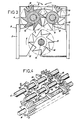
- the apparatus shown in Figures 1 to 4 comprises a frame (2) mounted on feet (3) supporting a housing (4) open both upwards and downwards.
- This frame serves as a support, with the interposition of bearings (5), to two parallel shafts (6), driven in rotation in opposite directions by means of a gear train (7) from a motor ( 8).
- a stack of crowns (9) each of which carries tools (10) at its periphery, and circular spacers (12).
- each crown (9) of a shaft is located opposite a spacer (12) of the other shaft.
- the crowns (9) are mounted on each shaft (6), so that the edges of the corresponding tools of the same stack of crowns are arranged in a circular helix, the circular helices corresponding to the two shafts being to not reverse.
- a scraper (13) integral with the frame (2) is in contact with each spacer (12) in the lower part thereof.
- this crusher is also equipped with a shaft (14), with an axis parallel to those of the shafts (6), arranged below these, and driven in rotation by a motor, not shown in the drawing, in the same direction as the shaft (6) located above .lui and to the left in Figure 3. It appears from this same figure that the shaft (14) is offset laterally by relative to the longitudinal median plane of the two shafts (6) on the side of the shaft (6) driven in the same direction as it.
- the frame (2) includes lights (15) for adjusting both the vertical and lateral positions of the shaft (14).
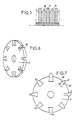
- FIG. 5 represents a variant of the assembly of FIGS. 1 to 4, in which the spacers (18), arranged between two rings (9) carrying the tools (10), have sharp ends (19), favoring the cutting of the products to be grind, which limits the torque required for grinding.
- each ring (9) has peripheral notches (20) of dovetail or other section, as shown in dotted lines, in which are intended to be fixed tools (10 ) comprising a heel (22) of shape complementary to that of a notch (20).
- This arrangement is very interesting because it allows, from standard crowns, to mount on them the tools best suited to the grinding to be carried out. In addition, if a tool is damaged, it can be replaced quickly and easily.
- the products to be ground are brought above the trees (6), where they are supported by the tools (10) that comprise the crowns (9). Due to the variable width opening formed by two corresponding series of teeth corresponding to the two shafts, products of different sizes and / or shapes can be taken care of by said tools, and driven between the two shafts where it is produced, always using tools, grinding the products which come out in the form of small particles at the bottom of the housing (4).
- the scraper (13), located in the lower part of each spacer (12) prevents an accumulation of crushed products against the spacers, which would be detrimental to the quality of the grinding.
- the products After passing between the shafts (6), the products come into contact with the shaft (14) rotating at a substantially higher speed; of the order of 50 revolutions per minute if the speed of the shafts (6) is of the order of 5 revolutions per minute.
- the shaft (14) perfects the grinding of the products and performs the cutting into small pieces of long elements which would not have been ground by passing between the two shafts (6).
- the invention brings a great improvement to the existing technique by providing a mill of simple design, the size of which can be adapted to the grinding to be carried out, requiring low power, and allowing starting under load.
- shafts could be of adjustable spacing, could each have a specific drive, or that this mill could have several stages, without departing from the scope of the invention.
Landscapes
- Engineering & Computer Science (AREA)
- Food Science & Technology (AREA)
- Crushing And Pulverization Processes (AREA)
- Processing Of Solid Wastes (AREA)
- Paper (AREA)
Claims (6)
Priority Applications (1)
| Application Number | Priority Date | Filing Date | Title |
|---|---|---|---|
| AT84420050T ATE28133T1 (de) | 1983-03-18 | 1984-03-19 | Zerkleinerungsmaschine fuer muell. |
Applications Claiming Priority (2)
| Application Number | Priority Date | Filing Date | Title |
|---|---|---|---|
| FR8304793A FR2542632B1 (fr) | 1983-03-18 | 1983-03-18 | Broyeur pour dechets |
| FR8304793 | 1983-03-18 |
Publications (2)
| Publication Number | Publication Date |
|---|---|
| EP0124449A1 EP0124449A1 (de) | 1984-11-07 |
| EP0124449B1 true EP0124449B1 (de) | 1987-07-08 |
Family
ID=9287155
Family Applications (1)
| Application Number | Title | Priority Date | Filing Date |
|---|---|---|---|
| EP84420050A Expired EP0124449B1 (de) | 1983-03-18 | 1984-03-19 | Zerkleinerungsmaschine für Müll |
Country Status (4)
| Country | Link |
|---|---|
| EP (1) | EP0124449B1 (de) |
| AT (1) | ATE28133T1 (de) |
| DE (1) | DE3464540D1 (de) |
| FR (1) | FR2542632B1 (de) |
Cited By (2)
| Publication number | Priority date | Publication date | Assignee | Title |
|---|---|---|---|---|
| DE102005061232A1 (de) * | 2005-12-20 | 2007-06-21 | Sbm Maschinen Gmbh | Vorrichtung zum Zerkleinern von Biomasse |
| CN106622550A (zh) * | 2017-03-08 | 2017-05-10 | 张春平 | 条状药材切粒机 |
Families Citing this family (22)
| Publication number | Priority date | Publication date | Assignee | Title |
|---|---|---|---|---|
| GB8432545D0 (en) * | 1984-12-21 | 1985-02-06 | Ofrex Group Plc | Shredding machines |
| GB8612202D0 (en) * | 1986-03-20 | 1986-06-25 | Mmd Design & Consult | Mineral breaker |
| DE3706855C3 (de) * | 1987-03-04 | 1993-12-02 | Schleicher Co Feinwerktech | Schneideinrichtung für Vorrichtungen zum Zerkleinern von Dokumenten etc. |
| US5025994A (en) * | 1989-11-15 | 1991-06-25 | Pelibe, An Ok Partnership | Medical waste grinder |
| GB2238965A (en) * | 1989-12-16 | 1991-06-19 | Lee King Lung | Chipper for scrap plastic |
| DE4023710A1 (de) * | 1990-07-26 | 1992-01-30 | Werner Buerklin | Vorrichtung zum zerkleinern von faserigem oder granulatartigem haufwerk wie muell |
| IT1269814B (it) * | 1994-05-20 | 1997-04-15 | Service Point Srl | Apparecchiatura per triturare oggetti di piccola taglia,in particolare mozziconi di sigarette |
| DE4423424C2 (de) * | 1994-07-06 | 2002-03-14 | Svedala Lindemann Gmbh | Rotorschere zum Zerkleinern von insbesondere sperrigen Abfällen |
| DE4444977C2 (de) * | 1994-12-16 | 1999-04-01 | Scheppach Maschf J | Zerkleinerungswerk |
| RU2135288C1 (ru) * | 1997-11-20 | 1999-08-27 | Открытое акционерное общество по буровому и транспортному оборудованию ОАО "Рудгормаш" | Дробилка для измельчения малопрочных материалов |
| DE19925729C1 (de) * | 1999-06-07 | 2000-12-28 | Henschel Recycling Technik Gmb | Vorrichtung zum Zerreißen von metallischem Schrott |
| RU2207908C1 (ru) * | 2001-11-12 | 2003-07-10 | Шардаков Антон Александрович | Устройство для измельчения бытовых и промышленных пластмассовых отходов |
| RU2324540C1 (ru) * | 2006-09-27 | 2008-05-20 | Антон Александрович Шардаков | Измельчитель пластмассовых отходов |
| ITCH20110003A1 (it) * | 2011-02-15 | 2012-08-16 | Luca Michele Tiberio | Alimentatore per generatore di calore a biomssa "3t" |
| CN102350392B (zh) * | 2011-10-26 | 2014-03-19 | 邢征 | 一种用于粉碎厨余垃圾的粉碎装置、粉碎机及粉碎压榨机 |
| DE102012216914B4 (de) * | 2012-09-20 | 2017-01-05 | Hammel GmbH & Co.KG | Zerkleinerungsvorrichtung |
| CN104069913B (zh) * | 2014-07-10 | 2016-01-13 | 太原重工股份有限公司 | 双齿辊破碎机 |
| CN104437734A (zh) * | 2014-12-04 | 2015-03-25 | 滁州市洪武报废汽车回收拆解利用有限公司 | 一种整车车架破碎系统 |
| GR1009916B (el) * | 2017-07-24 | 2021-01-28 | Σταυρος Μιχαλη Καριωτακης | Καταστροφεας κλαδιων με συστημα προωθησης των κλαδιων και συστημα επεξεργασιας των κλαδιων για παραγωγη βιομαζας |
| CN110385182A (zh) * | 2019-07-31 | 2019-10-29 | 枣庄鑫金山智能机械股份有限公司 | 一种带有废砂收集罩的制砂机 |
| CN112642529A (zh) * | 2020-12-21 | 2021-04-13 | 李书军 | 一种饲料处理装置 |
| CN118328401B (zh) * | 2024-05-13 | 2025-05-09 | 三荻建设工程技术(上海)股份有限公司 | 一种研磨输送机构及垃圾焚烧发电装置 |
Family Cites Families (11)
| Publication number | Priority date | Publication date | Assignee | Title |
|---|---|---|---|---|
| BE486486A (de) * | ||||
| FR394008A (fr) * | 1908-09-07 | 1909-01-12 | Rene Frugier | Appareil diviseur de mottes ou broyeur de matières argileuses ou autres |
| FR871657A (fr) * | 1941-04-21 | 1942-05-05 | Paget & Cie Ets | Concasseur perfectionné |
| FR984844A (fr) * | 1949-04-20 | 1951-07-11 | Appareil utilisable, notamment, comme broyeur et déchiqueteur | |
| FR1147882A (fr) * | 1955-09-26 | 1957-12-02 | Dispositif pour triturer des matières organiques, inorganiques et synthétiques | |
| FR1231719A (fr) * | 1958-04-11 | 1960-10-03 | Metallgesellschaft Ag | Procédé et installation pour homogénéiser le calibre de corps humides en grains de calibre hétérogène |
| US3502276A (en) * | 1967-06-01 | 1970-03-24 | Martin H Panning | Shredding machine |
| GB1206313A (en) * | 1968-02-09 | 1970-09-23 | Coal Industry Patents Ltd | Crushing apparatus |
| DE2702177A1 (de) * | 1977-01-20 | 1978-07-27 | Kloeckner Gmbh & Co Geb | Walzenzerkleinerungsmaschine |
| DE2943570A1 (de) * | 1979-10-29 | 1981-04-30 | Peter 5439 Bretthausen Voelskow | Zerkleinerungsmaschine fuer sperrige abfaelle |
| FR2508344A1 (fr) * | 1981-06-24 | 1982-12-31 | Dufourny Sprl Entr Edmond | Broyeur de dechets a taille helicoidale |
-
1983
- 1983-03-18 FR FR8304793A patent/FR2542632B1/fr not_active Expired
-
1984
- 1984-03-19 EP EP84420050A patent/EP0124449B1/de not_active Expired
- 1984-03-19 AT AT84420050T patent/ATE28133T1/de not_active IP Right Cessation
- 1984-03-19 DE DE8484420050T patent/DE3464540D1/de not_active Expired
Cited By (2)
| Publication number | Priority date | Publication date | Assignee | Title |
|---|---|---|---|---|
| DE102005061232A1 (de) * | 2005-12-20 | 2007-06-21 | Sbm Maschinen Gmbh | Vorrichtung zum Zerkleinern von Biomasse |
| CN106622550A (zh) * | 2017-03-08 | 2017-05-10 | 张春平 | 条状药材切粒机 |
Also Published As
| Publication number | Publication date |
|---|---|
| EP0124449A1 (de) | 1984-11-07 |
| ATE28133T1 (de) | 1987-07-15 |
| FR2542632A1 (fr) | 1984-09-21 |
| DE3464540D1 (en) | 1987-08-13 |
| FR2542632B1 (fr) | 1986-03-28 |
Similar Documents
| Publication | Publication Date | Title |
|---|---|---|
| EP0124449A1 (de) | Zerkleinerungsmaschine für Müll | |
| FR2834436A3 (fr) | Extracteur de jus de fruits et de legumes | |
| FR2508345A1 (de) | ||
| FR2616057A1 (fr) | Appareil d'epluchage de fruits et legumes | |
| FR2726966A1 (fr) | Dispositif de coupe et de transport pour des produits agricoles a tiges | |
| FR2533144A1 (fr) | Broyeur de dechets d'origine vegetale, minerale, synthetique, metallique ou analogues | |
| FR2651694A1 (fr) | Dispositif pour trier des produits juteux et collants. | |
| EP0420731A1 (de) | Messerbrecher-Zerkleinerer für Abfälle | |
| WO2001064018A1 (fr) | Appareil a dechiqueter les produits vegetaux | |
| EP1776856A1 (de) | Vegetations-Mähvorrichtung | |
| FR2520189A1 (fr) | Procede et appareil de reduction en fragments de souches | |
| FR2471811A1 (fr) | Broyeurs-dilacerateurs a fleaux, notamment a chaines | |
| EP0264330B1 (de) | Maschine zum Schneiden von Lebensmitteln, insbesondere Gemüse | |
| EP2949438B1 (de) | Pflanzenhäcksler zur erzeugung von kalibrierten partikeln | |
| FR2691079A1 (fr) | Broyeur compact notamment pour déchets. | |
| FR2681807A1 (fr) | Dispositif d'emincage de champignons. | |
| BE1001430A6 (fr) | Hache-betteraves. | |
| FR2552978A1 (fr) | Egrappoir pour vendange et analogues | |
| FR2542155A1 (fr) | Tete de coupe et machine de debroussaillage comportant une telle tete de coupe | |
| CA1118395A (fr) | Pulpeurs pour la desintegration des matieres de recuperation sales et tres dure, notamment des matieres resistantes a l'etat humide | |
| FR2507952A1 (fr) | Machine electrique a couper les ardoises naturelles | |
| FR2655569A1 (fr) | Broyeur de petite dimension pour vegetaux a entrainement a vitesse differentielle. | |
| FR2692500A1 (fr) | Broyeur pour déchets végétaux. | |
| FR2692871A1 (fr) | Appareil de reprise du talus résiduel de matériaux pulvérulents, pour silo à fond plat à vidange gravitaire. | |
| FR3142324A1 (fr) | Dispositif de lamier pour l’élagage et le broyage de végétaux |
Legal Events
| Date | Code | Title | Description |
|---|---|---|---|
| PUAI | Public reference made under article 153(3) epc to a published international application that has entered the european phase |
Free format text: ORIGINAL CODE: 0009012 |
|
| AK | Designated contracting states |
Designated state(s): AT BE CH DE FR GB IT LI LU NL SE |
|
| 17P | Request for examination filed |
Effective date: 19850502 |
|
| GRAA | (expected) grant |
Free format text: ORIGINAL CODE: 0009210 |
|
| AK | Designated contracting states |
Kind code of ref document: B1 Designated state(s): AT BE CH DE FR GB IT LI LU NL SE |
|
| PG25 | Lapsed in a contracting state [announced via postgrant information from national office to epo] |
Ref country code: NL Effective date: 19870708 Ref country code: IT Free format text: LAPSE BECAUSE OF FAILURE TO SUBMIT A TRANSLATION OF THE DESCRIPTION OR TO PAY THE FEE WITHIN THE PRESCRIBED TIME-LIMIT;WARNING: LAPSES OF ITALIAN PATENTS WITH EFFECTIVE DATE BEFORE 2007 MAY HAVE OCCURRED AT ANY TIME BEFORE 2007. THE CORRECT EFFECTIVE DATE MAY BE DIFFERENT FROM THE ONE RECORDED. Effective date: 19870708 Ref country code: AT Effective date: 19870708 |
|
| REF | Corresponds to: |
Ref document number: 28133 Country of ref document: AT Date of ref document: 19870715 Kind code of ref document: T |
|
| PG25 | Lapsed in a contracting state [announced via postgrant information from national office to epo] |
Ref country code: SE Effective date: 19870731 |
|
| REF | Corresponds to: |
Ref document number: 3464540 Country of ref document: DE Date of ref document: 19870813 |
|
| NLV1 | Nl: lapsed or annulled due to failure to fulfill the requirements of art. 29p and 29m of the patents act | ||
| PG25 | Lapsed in a contracting state [announced via postgrant information from national office to epo] |
Ref country code: LU Free format text: LAPSE BECAUSE OF NON-PAYMENT OF DUE FEES Effective date: 19880331 |
|
| PLBE | No opposition filed within time limit |
Free format text: ORIGINAL CODE: 0009261 |
|
| STAA | Information on the status of an ep patent application or granted ep patent |
Free format text: STATUS: NO OPPOSITION FILED WITHIN TIME LIMIT |
|
| 26N | No opposition filed | ||
| PG25 | Lapsed in a contracting state [announced via postgrant information from national office to epo] |
Ref country code: GB Effective date: 19890319 |
|
| PG25 | Lapsed in a contracting state [announced via postgrant information from national office to epo] |
Ref country code: LI Effective date: 19890331 Ref country code: CH Effective date: 19890331 Ref country code: BE Effective date: 19890331 |
|
| BERE | Be: lapsed |
Owner name: SOC. D'ETUDES ET DE REALISATION THERMIQUES S E R Effective date: 19890331 |
|
| GBPC | Gb: european patent ceased through non-payment of renewal fee | ||
| PG25 | Lapsed in a contracting state [announced via postgrant information from national office to epo] |
Ref country code: FR Free format text: LAPSE BECAUSE OF NON-PAYMENT OF DUE FEES Effective date: 19891130 |
|
| REG | Reference to a national code |
Ref country code: CH Ref legal event code: PL |
|
| PG25 | Lapsed in a contracting state [announced via postgrant information from national office to epo] |
Ref country code: DE Effective date: 19891201 |
|
| REG | Reference to a national code |
Ref country code: FR Ref legal event code: ST |