EP0124826A2 - Grille sous forme de rouleau pour usines d'incinération - Google Patents
Grille sous forme de rouleau pour usines d'incinération Download PDFInfo
- Publication number
- EP0124826A2 EP0124826A2 EP84104631A EP84104631A EP0124826A2 EP 0124826 A2 EP0124826 A2 EP 0124826A2 EP 84104631 A EP84104631 A EP 84104631A EP 84104631 A EP84104631 A EP 84104631A EP 0124826 A2 EP0124826 A2 EP 0124826A2
- Authority
- EP
- European Patent Office
- Prior art keywords
- grate
- central
- bars
- roller
- fixed point
- Prior art date
- Legal status (The legal status is an assumption and is not a legal conclusion. Google has not performed a legal analysis and makes no representation as to the accuracy of the status listed.)
- Granted
Links
Images

Classifications
-
- F—MECHANICAL ENGINEERING; LIGHTING; HEATING; WEAPONS; BLASTING
- F23—COMBUSTION APPARATUS; COMBUSTION PROCESSES
- F23H—GRATES; CLEANING OR RAKING GRATES
- F23H9/00—Revolving-grates; Rocking or shaking grates
- F23H9/02—Revolving cylindrical grates
-
- F—MECHANICAL ENGINEERING; LIGHTING; HEATING; WEAPONS; BLASTING
- F23—COMBUSTION APPARATUS; COMBUSTION PROCESSES
- F23H—GRATES; CLEANING OR RAKING GRATES
- F23H17/00—Details of grates
-
- F—MECHANICAL ENGINEERING; LIGHTING; HEATING; WEAPONS; BLASTING
- F23—COMBUSTION APPARATUS; COMBUSTION PROCESSES
- F23H—GRATES; CLEANING OR RAKING GRATES
- F23H3/00—Grates with hollow bars
- F23H3/02—Grates with hollow bars internally cooled
Definitions
- the invention relates to a roller grate according to the preamble of claim 1.
- Roller grates are used in waste incineration plants, in particular for the combustion of solid waste, e.g. Household waste, used.
- a roller grate consists of several grate rollers that are arranged in steps one behind the other and rotate slowly and in the same direction. The garbage is placed on the top grate roller, the rotation of the grate rollers means that it is transported and circulated during combustion.
- the grate rollers are covered on their circumference with grate bars, between which there are air slots for the combustion air. This is usually introduced axially into the grate rollers and then emerges radially through the air slots on the combustion chamber side. It also serves as cooling air for the grate bars.
- grate bars are used for covering: The majority of the grate surface is formed by middle grate bars suspended between grate bar supports, which are locked in segments with fixed point bars that are screwed onto the grate bar supports from the inside of the roller.
- the grate bars are exposed to heavy loads during operation, which is why they are subject to high wear, the height of which increases disproportionately with the temperature of the grate bars.
- occasional mechanical damage to the grate bars from components of the waste cannot be avoided. Wear and damage force the grate bars to be replaced regularly (possibly also irregularly).
- a generic roller grate is described in DE-PS 11 64 014.
- the roller grate consists of grate rollers with internals, through which the dripping metals are caught inside the grate roller.
- the aim is to prevent the air slots on the side facing away from the combustion chamber from becoming blocked. No information is given on how to prevent the clogging of the air slots on the combustion chamber side.
- a grate roller is known from US Pat. No. 3,469,544, which is covered with different central grate bars.
- central grate bars the heads of which are laterally toothed or wave-shaped, those with straight sides are also used on the axial edges of the grate rollers. It is not shown how the central grate bars are attached to the roller.
- the example of a central grate bar has serrated grate bars and no spacers.
- the invention has for its object to shorten the downtime of the roller grate forced by repair work on the grate roller coverings.
- the central grate bars execute relative movements in the longitudinal direction against one another during operation. This prevents clogging of the air slots between the grate bars due to caking.
- the feature of claim 2 leads to better cooling of the central grate bars with favorable effects on wear.
- the combustion air can be supplied with the combustion air in a targeted and uniform manner.
- the feature of claim 4 enables quick and easy replacement of the grate bars from the combustion chamber side.
- the feature of claim 6 prevents liquid metals from flowing into the interior of the grate roller.
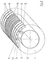
- the roller grate according to the invention is made up of a plurality of grate rollers 1 arranged one behind the other in steps.
- Each grate roller 1 consists of a drivable hollow shaft 2 in the form of a horizontal cylinder, on the circumferential surface of which holders 3 for grate bar supports 4 are fastened.
- Central grate bars 5 are suspended transversely between the grate bar supports 4, which run in a straight line and at the same distance from one another parallel to the hollow shaft axis.
- the central grate bars 5 thus form the casing of the grate roller 1.
- the outer surfaces 9.1 of the central grate bars 5 run on parallel, circumferential circular paths (grate burn paths), between which there are air slots 6. ( Figure 1).
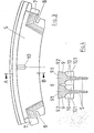
- the central grate bars 5 have a substantially T-shaped cross section, their longitudinal section essentially represents a circular section, the outer boundary line of which follows the circumference of the grate roller 1. ( Figure 3 and Figure 4).
- the outer surface 9.1 of a grate rod head 9 is smooth and flat, it forms part of the grate fire surface, and its side surfaces 9.2 are smooth and run in a straight line.
- the abutting side surfaces 9.2 two axially adjacent central grate bars 5 are kept at a distance by spacers 10, which are located on both sides on the long sides of the central grate bars 5; this creates the air slot 6 between them.
- the abutting surfaces 10.1 of the spacers 10 are smooth and flat.
- the circumferential grate combustion tracks are formed by fixed-point rods 11 (FIG. 1), which are screwed onto the grate rod support 4 instead of the suspended central grate rods 5. You lock the central grate bars 5, and since the grate bar supports 4 are interrupted in the area of the fixed point bars 11, the grate roller 1 is divided into segments.
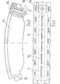
- the fixed point rods 11 are also curved in the longitudinal direction according to the circumference of the grate roller 1 (FIG. 5). On the front side they have a projection 12 which, after assembly, fits into a corresponding recess 13 at the foot end of the radially adjacent fixed point rod 11. The fit extends over the entire width of the fixed point rod 11, so there are no continuous vertical gaps at the transition point between two fixed point rods 11. In this way, the fit is secured against the passage of liquid metals.
- the focal surface 15 of the fixed point rods 11 additionally has openings 16 for the combustion air.
- grate bars 5 of different widths when building up a grate roller, e.g. narrower central grate bars in the central area of the grate roller than in their edge areas (FIG. 2), the supply of the combustion air into the fuel bed can be specifically controlled transversely to the transport direction. It is also possible to provide the individual grate rollers 1 of a roller grate with differently structured grate coverings in order to additionally optimize the combustion air supply in the direction of transport of the waste.
- the individual grate rollers 1 rotate in the direction of descent.
- the waste is added to the top grate roller 1, it is transported and circulated during the combustion.
- the combustion air flows axially into the grate rollers 1 and exits radially through the air slots 6 and the openings 16 in the fixed-point rods 11 on the upper side (combustion chamber side).
- a good heat transfer is guaranteed by the large surface area of the cooling fins, so that the central grate bars 5 are adequately cooled even with a high proportion of bulky waste. Due to the lower temperature of the grate during combustion, the wear is significantly reduced and the service life of the grate bars is extended considerably.
- the grate rollers 1 are loaded differently over their axial length. This leads to relative movements of the central grate bars 5 against one another along the grate combustion tracks. Clogging of the air slots 6 by baking metals is prevented.
- the fixed point rods 11 can be loosened from the combustion chamber side.
- the suspended central grate bars 5 can then simply be pulled out and replaced. This leads to a significant reduction in the downtime of the roller grate caused by repairs to the grate covering.
Landscapes
- Engineering & Computer Science (AREA)
- Chemical & Material Sciences (AREA)
- Combustion & Propulsion (AREA)
- Mechanical Engineering (AREA)
- General Engineering & Computer Science (AREA)
- Incineration Of Waste (AREA)
Priority Applications (1)
| Application Number | Priority Date | Filing Date | Title |
|---|---|---|---|
| AT84104631T ATE28504T1 (de) | 1983-05-05 | 1984-04-25 | Walzenrost fuer muellverbrennungsanlagen. |
Applications Claiming Priority (2)
| Application Number | Priority Date | Filing Date | Title |
|---|---|---|---|
| DE3316363 | 1983-05-05 | ||
| DE3316363A DE3316363A1 (de) | 1983-05-05 | 1983-05-05 | Walzenrost fuer muellverbrennungsanlagen |
Publications (3)
| Publication Number | Publication Date |
|---|---|
| EP0124826A2 true EP0124826A2 (fr) | 1984-11-14 |
| EP0124826A3 EP0124826A3 (en) | 1985-05-29 |
| EP0124826B1 EP0124826B1 (fr) | 1987-07-22 |
Family
ID=6198185
Family Applications (1)
| Application Number | Title | Priority Date | Filing Date |
|---|---|---|---|
| EP84104631A Expired EP0124826B1 (fr) | 1983-05-05 | 1984-04-25 | Grille sous forme de rouleau pour usines d'incinération |
Country Status (4)
| Country | Link |
|---|---|
| US (1) | US4537139A (fr) |
| EP (1) | EP0124826B1 (fr) |
| AT (1) | ATE28504T1 (fr) |
| DE (2) | DE3316363A1 (fr) |
Cited By (13)
| Publication number | Priority date | Publication date | Assignee | Title |
|---|---|---|---|---|
| EP0399898A1 (fr) * | 1989-05-25 | 1990-11-28 | Tunzini Picard Thermique Environnement | Rouleau de grille de foyer, notamment pour incinération de déchets, avec un garnissage tubulaire formé d'anneaux de barreaux séparés par des intervalles de soufflage de largeur maintenue |
| DE4300636C1 (de) * | 1993-01-13 | 1994-07-14 | Rbu Rolf Becker Gmbh Ingieneur | Walzenrost zum Betrieb eines Verbrennungskessels |
| EP2113718A2 (fr) | 2008-04-28 | 2009-11-04 | Vinci Environnement | Rouleau pour grille de four equipé d'un circuit de refroidissement |
| WO2011003823A1 (fr) | 2009-07-06 | 2011-01-13 | Sanofi-Aventis Deutschland Gmbh | Préparations d'insuline à effet retard |
| WO2011003822A2 (fr) | 2009-07-06 | 2011-01-13 | Sanofi-Aventis Deutschland Gmbh | Préparations d'insuline contenant de la méthionine |
| WO2011003820A1 (fr) | 2009-07-06 | 2011-01-13 | Sanofi-Aventis Deutschland Gmbh | Préparations d'insuline stables à la chaleur et aux agitations |
| EP2289539A1 (fr) | 2001-03-23 | 2011-03-02 | Sanofi-Aventis Deutschland GmbH | Préparations d'insuline sans zinc ou pauvre en zinc dotées d'une stabilité améliorée |
| EP2305288A2 (fr) | 2002-06-18 | 2011-04-06 | Sanofi-Aventis Deutschland GmbH | Préparations d'insuline amères dotées d'une stabilité améliorée |
| WO2014096985A2 (fr) | 2012-12-19 | 2014-06-26 | Wockhardt Limited | Composition aqueuse stable comprenant de l'insuline humaine ou un analogue ou un dérivé de celle-ci |
| WO2014102623A1 (fr) | 2012-12-26 | 2014-07-03 | Wockhardt Limited | Composition pharmaceutique |
| WO2015044922A1 (fr) | 2013-09-30 | 2015-04-02 | Wockhardt Limited | Composition pharmaceutique |
| WO2016001862A1 (fr) | 2014-07-04 | 2016-01-07 | Wockhardt Limited | Formulations à libération prolongée d'insulines |
| US9707176B2 (en) | 2009-11-13 | 2017-07-18 | Sanofi-Aventis Deutschland Gmbh | Pharmaceutical composition comprising a GLP-1 agonist and methionine |
Families Citing this family (10)
| Publication number | Priority date | Publication date | Assignee | Title |
|---|---|---|---|---|
| DE3341835A1 (de) * | 1983-11-19 | 1985-05-30 | Deutsche Babcock Anlagen Ag, 4200 Oberhausen | Rostbelag fuer feuerungsroste mit umlaufend bewegten rostbrennbahnen |
| DK0396908T3 (da) * | 1989-05-10 | 1994-09-19 | Babcock Anlagen Gmbh | Riststav og ristvalse |
| EP0981021A1 (fr) * | 1998-08-19 | 2000-02-23 | Asea Brown Boveri AG | Grille pour incinérateurs |
| AT410128B (de) * | 2000-11-08 | 2003-02-25 | Ferdinand Dipl Ing Tischler | Rost für feste brennstoffe |
| DE102004011834A1 (de) * | 2004-03-09 | 2005-10-06 | Fisia Babcock Environment Gmbh | Walzenrost |
| CH697973B1 (de) * | 2005-06-10 | 2009-04-15 | Alstom Technology Ltd | Rostwalze. |
| DE102007033825B4 (de) * | 2007-07-18 | 2021-05-20 | Nippon Steel & Sumikin Engineering Co., Ltd. | Walzenrost mit Hydraulikantrieb und ein Verfahren zum Betreiben des Walzenrostes |
| RU2371636C1 (ru) * | 2008-06-20 | 2009-10-27 | Государственное научное учреждение Всероссийский научно-исследовательский институт ветеринарной санитарии, гигиены и экологии Российской академии сельскохозяйственных наук (ГНУ ВНИИВСГЭ РОССЕЛЬХОЗАКАДЕМИИ) | Устройство для сжигания инфицированных и токсичных отходов |
| PL232801B1 (pl) * | 2017-03-14 | 2019-07-31 | Pellasx Spolka Z Ograniczona Odpowiedzialnoscia Spolka Komandytowa | Ruszt komory paleniskowej palnika do spalania pelletów, agropelletów i innych podobnego typu paliw stałych |
| KR102898639B1 (ko) * | 2025-08-12 | 2025-12-12 | 한종산업개발 주식회사 | 원통형 회전 화격자를 갖는 소각로 |
Family Cites Families (9)
| Publication number | Priority date | Publication date | Assignee | Title |
|---|---|---|---|---|
| DE206353C (fr) * | ||||
| GB191209555A (en) * | 1912-04-23 | 1913-03-27 | Joseph Ernst Fletcher | Improvements in Furnace Grates. |
| US1831816A (en) * | 1929-10-26 | 1931-11-17 | Charles B Magrath | Heating device |
| US2501763A (en) * | 1945-03-26 | 1950-03-28 | Charles T Denker | Solid fuel furnace of the rotary grate progressive feed type |
| FR1214713A (fr) * | 1958-02-01 | 1960-04-11 | Metallgesellschaft Ag | Construction de barreaux de grille |
| DE1164014B (de) * | 1962-05-25 | 1964-02-27 | Ver Kesselwerke Ag | Rostwalze fuer Walzenrost zur Muellverbrennung |
| DE1260665B (de) * | 1967-05-23 | 1968-02-08 | Ver Kesselwerke Ag | Rostbelag fuer die Rostwalzen eines Walzenrostes in Muellverbrennungsanlagen |
| DE2839536C3 (de) * | 1978-09-11 | 1981-10-15 | Rheinische Eisengießerei Wilhelm Pulch KG, 4030 Ratingen | Roststab für Walzenroste einer Verbrennungsanlage |
| CH637198A5 (de) * | 1979-03-14 | 1983-07-15 | Widmer & Ernst Ag | Feuerungsrost fuer verbrennungsoefen. |
-
1983
- 1983-05-05 DE DE3316363A patent/DE3316363A1/de active Granted
-
1984
- 1984-04-25 EP EP84104631A patent/EP0124826B1/fr not_active Expired
- 1984-04-25 AT AT84104631T patent/ATE28504T1/de not_active IP Right Cessation
- 1984-04-25 DE DE8484104631T patent/DE3464956D1/de not_active Expired
- 1984-05-03 US US06/608,022 patent/US4537139A/en not_active Expired - Lifetime
Cited By (17)
| Publication number | Priority date | Publication date | Assignee | Title |
|---|---|---|---|---|
| FR2647532A1 (fr) * | 1989-05-25 | 1990-11-30 | Picard Fours | Rouleau de grille de foyer, notamment pour incineration de dechets, avec un garnissage tubulaire forme d'anneaux de barreaux separes par des intervalles de soufflage de largeur maintenue |
| US5057011A (en) * | 1989-05-25 | 1991-10-15 | Fours Picard | Furnace grate roller namely for incinerating refuse with a tubular casing formed by rings of bars separated by blow gaps of set width |
| EP0399898A1 (fr) * | 1989-05-25 | 1990-11-28 | Tunzini Picard Thermique Environnement | Rouleau de grille de foyer, notamment pour incinération de déchets, avec un garnissage tubulaire formé d'anneaux de barreaux séparés par des intervalles de soufflage de largeur maintenue |
| DE4300636C1 (de) * | 1993-01-13 | 1994-07-14 | Rbu Rolf Becker Gmbh Ingieneur | Walzenrost zum Betrieb eines Verbrennungskessels |
| EP2289539A1 (fr) | 2001-03-23 | 2011-03-02 | Sanofi-Aventis Deutschland GmbH | Préparations d'insuline sans zinc ou pauvre en zinc dotées d'une stabilité améliorée |
| EP2305288A2 (fr) | 2002-06-18 | 2011-04-06 | Sanofi-Aventis Deutschland GmbH | Préparations d'insuline amères dotées d'une stabilité améliorée |
| EP2113718A2 (fr) | 2008-04-28 | 2009-11-04 | Vinci Environnement | Rouleau pour grille de four equipé d'un circuit de refroidissement |
| WO2011003820A1 (fr) | 2009-07-06 | 2011-01-13 | Sanofi-Aventis Deutschland Gmbh | Préparations d'insuline stables à la chaleur et aux agitations |
| WO2011003822A2 (fr) | 2009-07-06 | 2011-01-13 | Sanofi-Aventis Deutschland Gmbh | Préparations d'insuline contenant de la méthionine |
| WO2011003823A1 (fr) | 2009-07-06 | 2011-01-13 | Sanofi-Aventis Deutschland Gmbh | Préparations d'insuline à effet retard |
| EP3202394A1 (fr) | 2009-07-06 | 2017-08-09 | Sanofi-Aventis Deutschland GmbH | Préparations aqueuses de l´insuline contenant de la méthionine |
| US12558307B2 (en) | 2009-07-06 | 2026-02-24 | Sanofi-Aventis | Insulin preparations containing methionine |
| US9707176B2 (en) | 2009-11-13 | 2017-07-18 | Sanofi-Aventis Deutschland Gmbh | Pharmaceutical composition comprising a GLP-1 agonist and methionine |
| WO2014096985A2 (fr) | 2012-12-19 | 2014-06-26 | Wockhardt Limited | Composition aqueuse stable comprenant de l'insuline humaine ou un analogue ou un dérivé de celle-ci |
| WO2014102623A1 (fr) | 2012-12-26 | 2014-07-03 | Wockhardt Limited | Composition pharmaceutique |
| WO2015044922A1 (fr) | 2013-09-30 | 2015-04-02 | Wockhardt Limited | Composition pharmaceutique |
| WO2016001862A1 (fr) | 2014-07-04 | 2016-01-07 | Wockhardt Limited | Formulations à libération prolongée d'insulines |
Also Published As
| Publication number | Publication date |
|---|---|
| DE3316363C2 (fr) | 1991-10-17 |
| ATE28504T1 (de) | 1987-08-15 |
| DE3316363A1 (de) | 1984-11-08 |
| DE3464956D1 (en) | 1987-08-27 |
| EP0124826B1 (fr) | 1987-07-22 |
| EP0124826A3 (en) | 1985-05-29 |
| US4537139A (en) | 1985-08-27 |
Similar Documents
| Publication | Publication Date | Title |
|---|---|---|
| EP0124826B1 (fr) | Grille sous forme de rouleau pour usines d'incinération | |
| EP0811818B2 (fr) | Plaque de grille et procédé pour sa fabrication | |
| EP1992897B1 (fr) | Procédé et dispositif destinés à refroidir une couche de produits en vrac se trouvant sur une grille de transport | |
| EP0499912B1 (fr) | Barreau de grille et grille pour installations de combustion | |
| EP0157920B1 (fr) | Rouleau de grille pour grille à rouleaux par exemple d'une installation d'incinération des ordures ou similaire | |
| EP0165432B1 (fr) | Four, notamment pour la combustion des ordures, du charbon, du bois et des déchets industriels | |
| EP0216346B1 (fr) | Machine pour le traitement thermique | |
| DE3421365C1 (de) | Tunnelofen | |
| DE2522070A1 (de) | Walzgutfuehrung fuer ein walzgeruest | |
| WO1999032830A1 (fr) | Barreau de grille pour grille de combustion et procede pour son refroidissement | |
| DE3813441C2 (fr) | ||
| CH636178A5 (de) | Rostbelag, insbesondere fuer grossfeuerungen. | |
| DE19851471A1 (de) | Durchfallarmer Vorschubrostbelag | |
| DE3322139A1 (de) | Rostkuehler | |
| DE1164014B (de) | Rostwalze fuer Walzenrost zur Muellverbrennung | |
| DE2000631B2 (de) | Wärmetauscher mit kontinuierlicher Schüttgutförderung | |
| DE942202C (de) | Sieb, insbesondere fuer Setz- und Siebanlagen | |
| DE19907944A1 (de) | Rostplatte für einen Vorschubrost | |
| DE3341835C2 (fr) | ||
| DE19952198A1 (de) | Rostwalze für einen Walzenrost | |
| DE2359635C3 (de) | Treppenrost für einen Verbrennungsofen | |
| DE1526051C2 (de) | Fluessigkeitsgekuehlter Vorschubrost fuer das Verbrennen von Schlaemmen | |
| EP0606551B2 (fr) | Grille à rouleaux pour une chaudière à combustion | |
| EP1178277A1 (fr) | Procédé et installation pour uniformiser le flux de matières traitées expulsées d'un four rotatif vers le refroidisseur | |
| DE69400303T2 (de) | Halterungsanordnung für Widerstandsbänder für Leistungswiderstände |
Legal Events
| Date | Code | Title | Description |
|---|---|---|---|
| PUAI | Public reference made under article 153(3) epc to a published international application that has entered the european phase |
Free format text: ORIGINAL CODE: 0009012 |
|
| AK | Designated contracting states |
Designated state(s): AT BE CH DE FR GB IT LI LU NL SE |
|
| PUAL | Search report despatched |
Free format text: ORIGINAL CODE: 0009013 |
|
| AK | Designated contracting states |
Designated state(s): AT BE CH DE FR GB IT LI LU NL SE |
|
| 17P | Request for examination filed |
Effective date: 19850625 |
|
| 17Q | First examination report despatched |
Effective date: 19860206 |
|
| ITF | It: translation for a ep patent filed | ||
| GRAA | (expected) grant |
Free format text: ORIGINAL CODE: 0009210 |
|
| AK | Designated contracting states |
Kind code of ref document: B1 Designated state(s): AT BE CH DE FR GB IT LI LU NL SE |
|
| REF | Corresponds to: |
Ref document number: 28504 Country of ref document: AT Date of ref document: 19870815 Kind code of ref document: T |
|
| REF | Corresponds to: |
Ref document number: 3464956 Country of ref document: DE Date of ref document: 19870827 |
|
| ET | Fr: translation filed | ||
| PG25 | Lapsed in a contracting state [announced via postgrant information from national office to epo] |
Ref country code: LU Free format text: LAPSE BECAUSE OF NON-PAYMENT OF DUE FEES Effective date: 19880430 |
|
| PLBI | Opposition filed |
Free format text: ORIGINAL CODE: 0009260 |
|
| 26 | Opposition filed |
Opponent name: MUELLVERBRENNUNGSANLAGE WUPPERTAL GMBH Effective date: 19880121 |
|
| NLR1 | Nl: opposition has been filed with the epo |
Opponent name: MUELLVERBRENNUNGSANLAGE WUPPERTAL GMBH |
|
| PGFP | Annual fee paid to national office [announced via postgrant information from national office to epo] |
Ref country code: BE Payment date: 19900109 Year of fee payment: 7 |
|
| PGFP | Annual fee paid to national office [announced via postgrant information from national office to epo] |
Ref country code: LU Payment date: 19900216 Year of fee payment: 7 |
|
| PGFP | Annual fee paid to national office [announced via postgrant information from national office to epo] |
Ref country code: AT Payment date: 19900219 Year of fee payment: 7 |
|
| PGFP | Annual fee paid to national office [announced via postgrant information from national office to epo] |
Ref country code: CH Payment date: 19900220 Year of fee payment: 7 |
|
| PGFP | Annual fee paid to national office [announced via postgrant information from national office to epo] |
Ref country code: FR Payment date: 19900302 Year of fee payment: 7 |
|
| PGFP | Annual fee paid to national office [announced via postgrant information from national office to epo] |
Ref country code: DE Payment date: 19900410 Year of fee payment: 7 |
|
| PGFP | Annual fee paid to national office [announced via postgrant information from national office to epo] |
Ref country code: SE Payment date: 19900412 Year of fee payment: 7 |
|
| PGFP | Annual fee paid to national office [announced via postgrant information from national office to epo] |
Ref country code: GB Payment date: 19900417 Year of fee payment: 7 |
|
| ITTA | It: last paid annual fee | ||
| PGFP | Annual fee paid to national office [announced via postgrant information from national office to epo] |
Ref country code: NL Payment date: 19900430 Year of fee payment: 7 |
|
| RDAG | Patent revoked |
Free format text: ORIGINAL CODE: 0009271 |
|
| STAA | Information on the status of an ep patent application or granted ep patent |
Free format text: STATUS: PATENT REVOKED |
|
| GBPR | Gb: patent revoked under art. 102 of the ep convention designating the uk as contracting state | ||
| REG | Reference to a national code |
Ref country code: CH Ref legal event code: PL |
|
| 27W | Patent revoked |
Effective date: 19900329 |
|
| NLR2 | Nl: decision of opposition | ||
| BERE | Be: lapsed |
Owner name: DEUTSCHE BABCOCK ANLAGEN A.G. Effective date: 19910430 |
|
| EUG | Se: european patent has lapsed |
Ref document number: 84104631.1 Effective date: 19900816 |