EP0125164A1 - Verfahren zur Ermittlung der Eigenschaften einer flüssigkeitsführenden, unterirdischen Formation - Google Patents
Verfahren zur Ermittlung der Eigenschaften einer flüssigkeitsführenden, unterirdischen Formation Download PDFInfo
- Publication number
- EP0125164A1 EP0125164A1 EP84400781A EP84400781A EP0125164A1 EP 0125164 A1 EP0125164 A1 EP 0125164A1 EP 84400781 A EP84400781 A EP 84400781A EP 84400781 A EP84400781 A EP 84400781A EP 0125164 A1 EP0125164 A1 EP 0125164A1
- Authority
- EP
- European Patent Office
- Prior art keywords
- theoretical
- experimental
- well
- graph
- fluid
- Prior art date
- Legal status (The legal status is an assumption and is not a legal conclusion. Google has not performed a legal analysis and makes no representation as to the accuracy of the status listed.)
- Granted
Links
Images

Classifications
-
- E—FIXED CONSTRUCTIONS
- E21—EARTH OR ROCK DRILLING; MINING
- E21B—EARTH OR ROCK DRILLING; OBTAINING OIL, GAS, WATER, SOLUBLE OR MELTABLE MATERIALS OR A SLURRY OF MINERALS FROM WELLS
- E21B49/00—Testing the nature of borehole walls; Formation testing; Methods or apparatus for obtaining samples of soil or well fluids, specially adapted to earth drilling or wells
- E21B49/008—Testing the nature of borehole walls; Formation testing; Methods or apparatus for obtaining samples of soil or well fluids, specially adapted to earth drilling or wells by injection test; by analysing pressure variations in an injection or production test, e.g. for estimating the skin factor
Definitions
- the present invention relates to hydrocarbon well tests, making it possible to determine the physical characteristics of the system formed by a well and an underground formation (also called “reservoir") producing hydrocarbons through the well. More specifically, the invention relates to a method according to which the flow of fluid produced by the well is modified by closing or opening a valve which is located on the surface or in the well. The resulting pressure variations are measured and recorded at the bottom of the well as a function of the time elapsed since the start of the tests, that is to say since the modification of the flow rate. The characteristics of the underground well-formation system can be deduced from these experimental data.
- the experimental data from the well tests are analyzed by comparing the response of the underground formation to a change in the flow rate of the fluid produced, with the behavior of theoretical models having well-defined characteristics and subjected to the same change in flow rate as the formation studied.
- the variations of pressure as a function of time characterize the behavior of the well-formation system and the removal at constant flow rate of fluids, by the opening of a valve in the initially closed well, is the test condition which is applied to training and theoretical model.
- the system studied and the theoretical model are identical both quantitatively and qualitatively. In other words, these tanks are assumed to have the same physical characteristics.
- the characteristics obtained from this comparison depend on the theoretical model: the more complicated the model, the more numerous the characteristics that can be determined.
- the basic model is represented by a homogeneous formation with upper and lower limits impermeable and with infinite radial extension. The flow in the formation is then radial, directed towards the well.
- the wall effect is defined by a coefficient S which characterizes the damage or stimulation of the part of the formation adjacent to the well.
- the compression or decompression effect of the fluid in the well is characterized by a coefficient C which results from the difference in fluid flow produced by the well, between the underground formation and the wellhead, when a valve located at the head well is either closed or open.
- the coefficient C is usually expressed in barrels per psi, one barrel being equal to 0.16m 3 and one psi equal to 0.069 bar.
- each curve is characterized by one or more dimensionless numbers which each represent a characteristic (or a combination of characteristics) of the theoretical system formed by a well and a reservoir.
- a dimensionless parameter is defined by the actual parameter (pressure for example) multiplied by an expression that includes certain characteristics of the well-reservoir system so as to make the dimensionless parameter independent of these characteristics.
- the coefficient S characterizes only the wall effect but is independent of the other characteristics of the reservoir and experimental conditions such as the flow rate, the viscosity of the fluid, the permeability of the formation, etc.
- the experimental curve and one of the standard curves represented with the same coordinate scales have an identical shape but are offset with respect to each other.
- the offsets along the two axes, on the ordinate for pressure and on the abscissa for time, are proportional to the characteristic values of the well-reservoir system which can thus be determined.
- Qualitative information on the underground formation is obtained by the identification of the different regimes on the graph in logarithmic scale representing the experimental data. Knowing that a particular characteristic of the well-reservoir system, such as for example a vertical fracture, is characterized by a particular regime, all the different regimes appearing on the graph of the experimental data are identified in order to select the appropriate model of well-reservoir system. . Specialized graphs taking into account only part of the experimental data allow the more precise determination of the characteristics of the system. We then return to the graph on a logarithmic scale taking into account all the data to confirm the choice of the system and the quantitative determination of the characteristics of the training. The latter are obtained by selecting a standard curve having the same shape as the experimental curve and by determining the offset of the coordinate axes of the experimental curve with respect to the theoretical curve.
- the patent of the United States of America 4,328,705 also describes a method according to which the standard curves are represented using the dimensionless pressure P for the ordinate axis and the ratio t D / C D for the abscissa axis, t D being dimensionless time and C D dimensionless coefficient characterizing the effect of compression or decompression of the fluid in the well.
- the disadvantage of the method described in this patent is that the standard curves have shapes varying relatively slowly with respect to each other. This results in a certain uncertainty in the choice of the standard curve corresponding to the experimental curve.
- the present invention relates to a method for determining the characteristics of a well-reservoir system allowing better identification between the experimental behavior of the analyzed system formed by the well and the underground formation and the behavior of a theoretical model.
- This model is general, namely that the formation can be homogeneous or heterogeneous and that it takes into account the wall effect and the effect of compression or decompression of the fluid and possibly the double porosity of the reservoir and fractures of the well.
- the method according to the present invention allows a global and unique analysis of the behavior of the well-reservoir system, without resorting to specialized analyzes.
- the invention also allows the analysis of experimental data when the condition imposed on the system is the closing of the well, thanks to a judicious choice of parameters.
- the method according to the present invention can also be advantageously combined with a method of the prior art.
- Said theoretical evolution can advantageously be that of the logarithm of the product P ' D ⁇ t D / C D as a function of the logarithm of t D / C D and said experimental evolution is that of the logarithm of the product ⁇ P'. ⁇ t as a function of the logarithm of ⁇ t.
- Said theoretical evolution can also be a function of an index representing a quantity characteristic of the product C D e 2S .
- said theoretical evolution can also be a function of an index representing a quantity characteristic of the product C D e 2S .
- the experimental curve correspond with one of the standard curves of the theoretical graph and we can determine certain physical characteristics of the underground well-formation system.
- the subject of the invention is also the theoretical graphs obtained as indicated above.
- Pressure variations as a function of time can be monitored using a probe lowered into the well at the end of a cable.
- the cable can be electric and in this case transmit the pressure information directly to a recorder located on the surface.
- the pressure variations are recorded in memories located in the probe. These memories are then read on the surface.
- You can also install a pressure gauge in a side pocket of the production column of the well, near the producing formation.
- a conductive cable located in the annular space between the production column and the casing connects the pressure gauge to a recorder located on the surface.
- the values measured by the pressure probes generally do not correspond to the pressure itself, but to a quantity characteristic of the pressure such as, for example, a difference of two frequencies. Thereafter, the expression "pressure value" will be used for convenience and clarity, while bearing in mind that the experimental data may correspond to a quantity characteristic of the pressure.
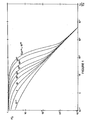
- the graph in Figure 1 characterizes the behavior of a homogeneous reservoir model and a well exhibiting the wall effect and the effect of compression or decompression of the fluid in the well.
- the curves of FIG. 1 are characterized by three distinct parts: the left part of the graph corresponding to short times and being characteristic of the effect of decompression of the fluid from the well (this effect is most important at the opening of the valve) ; the right part of the graph corresponding to a pure radial flow from the reservoir and an intermediate part between the left and right parts corresponding to a transient flow regime between the two preceding limit flows.
- This intermediate flow is a function of the decompression effect of the fluid and of the wall effect.
- the curves tend towards an asymptote corresponding to a derivative equal to 1. Indeed, at the very beginning of the tests, the predominant phenomenon is the decompression effect of the well which is characterized by the equation:
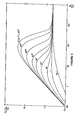
- the ordinate axis corresponds to P ' D ⁇ t D / C D and the abscissa axis corresponds to t D / C D' P ' D being the derivative of P with respect to t D / C D.
- Equation (7) can be written: It follows that for long times, the value of the product P ' D ⁇ t D / C D is equal to 0.5 and that the standard curves tend towards an asymptote of zero slope.
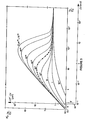
- FIG. 3 illustrates the use of the graph of the standard curves of FIG. 2. This graph has been reproduced in FIG.
- the value of the coefficient S of the wall effect is determined by the correspondence of the experimental curve with one of the standard curves, the correspondence of the two curves leading to the value of C D e 2S .
- the value of C D is determined by the value of C by the following equation: in which ⁇ c t h represents the porosity-compressibility-thickness product, known from geological studies (such as for example, analysis of samples or electrical logs) and r is the radius of the well.
- the value of the coefficient S can therefore be calculated from the value of C D e 2S .
- the standard curves represented in FIGS. 1 and 2 correspond to the behavior of a theoretical model of homogeneous formation when suddenly an increase in the flow rate of the fluid produced by the formation is imposed, and more especially when a valve is opened on the surface of the well to make it produce at constant flow while it was closed before ("drawdown" curve).
- the experimental curve is plotted on a logarithmic scale by plotting the time intervals A t on the abscissa and on the ordinate: tp representing the duration during which the training was put into production.
- the analysis of well tests can then be done by comparing this experimental curve with the standard curves of the graph in Figure 2.
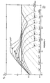
- FIG. 4 shows an example of application to a formation with double porosity.
- the fluid produced by the formation is contained in the matrix, that is to say in the rock composing the formation, and in the interstices or cracks contained in the matrix. There is therefore a system in which the fluid contained in the matrix first flows through the cracks before passing into the well.
- the coefficient w characterizes the ratio of the volume of fluid produced by the cracks to the volume of fluid produced by the total system (matrix + crack).
- the coefficient A characterizes the delay of the matrix to produce the fluid in the cracks compared to the production of the cracks themselves.
- the graph in Figure 4 corresponds to a theoretical training model with double porosity. On this graph, we have represented, in solid lines, the standard curves corresponding to the homogeneous model, identical to those of FIG. 2, in dotted lines of the standard curves by choosing as index and semi-dotted standard curves by choosing as index The dotted curves represent the equation: The semi-dotted curves represent the equation:
- a typical experimental curve characterizing a double porosity formation has also been represented by points.
- the use of the graph in FIG. 4 makes it possible to determine the values of the coefficients w and ⁇ , in addition to the values of kh, C and S. Note that the curves characterizing the behavior of a heterogeneous model have a very marked shape by applying the method according to the present invention.
- the present invention also makes it possible to plot on the same theoretical graph the standard curves of FIG. 2, P ' D ⁇ t D / C D as a function of t D / C D but also the standard curves P as a function of t D / C D described in United States Patent No. 4,328,705.
- the juxtaposition of these two series of standard curves on the same graph is shown in Figure 5.
- the method for determining the characteristics of an underground formation which has just been described has many advantages.
- the analysis of well tests can be carried out using a single graph, while the methods of the prior art call on a general graph on a logarithmic scale using all the experimental data and on a graph. specialized in semi-logarithmic scale and taking into account only part of the experimental data.
- the combination of the standard curves of the prior art with the standard curves of the present invention on the same graph has a certain advantage.
Landscapes
- Engineering & Computer Science (AREA)
- Mining & Mineral Resources (AREA)
- Geology (AREA)
- Life Sciences & Earth Sciences (AREA)
- Fluid Mechanics (AREA)
- Environmental & Geological Engineering (AREA)
- Chemical & Material Sciences (AREA)
- Physics & Mathematics (AREA)
- Analytical Chemistry (AREA)
- General Life Sciences & Earth Sciences (AREA)
- Geochemistry & Mineralogy (AREA)
- Geophysics And Detection Of Objects (AREA)
- Testing Or Calibration Of Command Recording Devices (AREA)
- Investigating Or Analysing Biological Materials (AREA)
- Sampling And Sample Adjustment (AREA)
Applications Claiming Priority (2)
| Application Number | Priority Date | Filing Date | Title |
|---|---|---|---|
| FR8307075A FR2544790B1 (fr) | 1983-04-22 | 1983-04-22 | Methode de determination des caracteristiques d'une formation souterraine produisant un fluide |
| FR8307075 | 1983-04-22 |
Publications (2)
| Publication Number | Publication Date |
|---|---|
| EP0125164A1 true EP0125164A1 (de) | 1984-11-14 |
| EP0125164B1 EP0125164B1 (de) | 1986-12-30 |
Family
ID=9288354
Family Applications (1)
| Application Number | Title | Priority Date | Filing Date |
|---|---|---|---|
| EP84400781A Expired EP0125164B1 (de) | 1983-04-22 | 1984-04-19 | Verfahren zur Ermittlung der Eigenschaften einer flüssigkeitsführenden, unterirdischen Formation |
Country Status (6)
| Country | Link |
|---|---|
| US (1) | US4597290A (de) |
| EP (1) | EP0125164B1 (de) |
| CA (1) | CA1209699A (de) |
| DE (1) | DE3461844D1 (de) |
| FR (1) | FR2544790B1 (de) |
| NO (1) | NO841473L (de) |
Cited By (4)
| Publication number | Priority date | Publication date | Assignee | Title |
|---|---|---|---|---|
| GB2161943A (en) * | 1984-07-19 | 1986-01-22 | Prad Res & Dev Nv | Method for estimating porosity and/or permeability |
| FR2573473A1 (fr) * | 1984-11-20 | 1986-05-23 | Reijonen Veli Oy | Procede de determination de la capacite de puits d'eaux souterraines |
| US6832515B2 (en) | 2002-09-09 | 2004-12-21 | Schlumberger Technology Corporation | Method for measuring formation properties with a time-limited formation test |
| US7178392B2 (en) | 2003-08-20 | 2007-02-20 | Schlumberger Technology Corporation | Determining the pressure of formation fluid in earth formations surrounding a borehole |
Families Citing this family (37)
| Publication number | Priority date | Publication date | Assignee | Title |
|---|---|---|---|---|
| FR2569762B1 (fr) * | 1984-08-29 | 1986-09-19 | Flopetrol Sa Etu Fabrications | Procede d'essai de puits d'hydrocarbures |
| FR2585404B1 (fr) * | 1985-07-23 | 1988-03-18 | Flopetrol | Procede de determination des parametres de formations a plusieurs couches productrices d'hydrocarbures |
| NO170037C (no) * | 1985-07-23 | 1992-09-02 | Flopetrol Services Inc | Fremgangsmaate for maaling av stroemningshastigheter i en borebroenn. |
| EP0429078A1 (de) * | 1986-05-15 | 1991-05-29 | Soletanche | Verfahren und Vorrichtung zum Messen der Grunddurchlässigkeit |
| FR2613418B1 (fr) * | 1987-04-02 | 1995-05-19 | Schlumberger Cie Dowell | Procede de traitement matriciel dans le domaine petrolier |
| US4797821A (en) * | 1987-04-02 | 1989-01-10 | Halliburton Company | Method of analyzing naturally fractured reservoirs |
| US4843878A (en) * | 1988-09-22 | 1989-07-04 | Halliburton Logging Services, Inc. | Method and apparatus for instantaneously indicating permeability and horner plot slope relating to formation testing |
| US5050674A (en) * | 1990-05-07 | 1991-09-24 | Halliburton Company | Method for determining fracture closure pressure and fracture volume of a subsurface formation |
| US5005643A (en) * | 1990-05-11 | 1991-04-09 | Halliburton Company | Method of determining fracture parameters for heterogenous formations |
| US5517593A (en) * | 1990-10-01 | 1996-05-14 | John Nenniger | Control system for well stimulation apparatus with response time temperature rise used in determining heater control temperature setpoint |
| US5247829A (en) * | 1990-10-19 | 1993-09-28 | Schlumberger Technology Corporation | Method for individually characterizing the layers of a hydrocarbon subsurface reservoir |
| FR2710687B1 (fr) * | 1993-09-30 | 1995-11-10 | Elf Aquitaine | Procédé d'évaluation de l'endommagement de la structure d'une roche entourant un puits. |
| US5501273A (en) * | 1994-10-04 | 1996-03-26 | Amoco Corporation | Method for determining the reservoir properties of a solid carbonaceous subterranean formation |
| FR2747729B1 (fr) * | 1996-04-23 | 1998-07-03 | Elf Aquitaine | Methode d'identification automatique de la nature d'un puits de production d'hydrocarbures |
| US7031841B2 (en) * | 2004-01-30 | 2006-04-18 | Schlumberger Technology Corporation | Method for determining pressure of earth formations |
| DE602005013483D1 (de) * | 2005-02-28 | 2009-05-07 | Schlumberger Technology Bv | Verfahren zur Messung von Formationseigenschaften mit einem Formationstester |
| US7712524B2 (en) * | 2006-03-30 | 2010-05-11 | Schlumberger Technology Corporation | Measuring a characteristic of a well proximate a region to be gravel packed |
| US7793718B2 (en) * | 2006-03-30 | 2010-09-14 | Schlumberger Technology Corporation | Communicating electrical energy with an electrical device in a well |
| US7735555B2 (en) * | 2006-03-30 | 2010-06-15 | Schlumberger Technology Corporation | Completion system having a sand control assembly, an inductive coupler, and a sensor proximate to the sand control assembly |
| US8056619B2 (en) | 2006-03-30 | 2011-11-15 | Schlumberger Technology Corporation | Aligning inductive couplers in a well |
| US20080230221A1 (en) * | 2007-03-21 | 2008-09-25 | Schlumberger Technology Corporation | Methods and systems for monitoring near-wellbore and far-field reservoir properties using formation-embedded pressure sensors |
| US7580797B2 (en) * | 2007-07-31 | 2009-08-25 | Schlumberger Technology Corporation | Subsurface layer and reservoir parameter measurements |
| US8121790B2 (en) * | 2007-11-27 | 2012-02-21 | Schlumberger Technology Corporation | Combining reservoir modeling with downhole sensors and inductive coupling |
| US8136395B2 (en) | 2007-12-31 | 2012-03-20 | Schlumberger Technology Corporation | Systems and methods for well data analysis |
| US8078402B2 (en) * | 2008-07-16 | 2011-12-13 | Schlumberger Technology Corporation | Method of ranking geomarkers and compositional allocation of wellbore effluents |
| US20100147066A1 (en) * | 2008-12-16 | 2010-06-17 | Schlumberger Technology Coporation | Method of determining end member concentrations |
| US8839850B2 (en) * | 2009-10-07 | 2014-09-23 | Schlumberger Technology Corporation | Active integrated completion installation system and method |
| US20110192596A1 (en) * | 2010-02-07 | 2011-08-11 | Schlumberger Technology Corporation | Through tubing intelligent completion system and method with connection |
| US9249559B2 (en) | 2011-10-04 | 2016-02-02 | Schlumberger Technology Corporation | Providing equipment in lateral branches of a well |
| US9644476B2 (en) | 2012-01-23 | 2017-05-09 | Schlumberger Technology Corporation | Structures having cavities containing coupler portions |
| US9175560B2 (en) | 2012-01-26 | 2015-11-03 | Schlumberger Technology Corporation | Providing coupler portions along a structure |
| US9938823B2 (en) | 2012-02-15 | 2018-04-10 | Schlumberger Technology Corporation | Communicating power and data to a component in a well |
| US20130282286A1 (en) * | 2012-04-20 | 2013-10-24 | Chevron U.S.A. Inc. | System and method for calibrating permeability for use in reservoir modeling |
| US10036234B2 (en) | 2012-06-08 | 2018-07-31 | Schlumberger Technology Corporation | Lateral wellbore completion apparatus and method |
| GB2499523B (en) * | 2013-02-15 | 2014-04-09 | Petroleum Experts Ltd | Modelling of transient hydrocarbon reservoirs |
| US12234717B2 (en) | 2018-11-08 | 2025-02-25 | Halliburton Energy Services, Inc. | Effective wellbore compressibility determination apparatus, methods, and systems |
| CN114060018B (zh) * | 2020-08-04 | 2024-05-28 | 中国石油天然气股份有限公司 | 一种储层动态储量确定方法、系统、设备及可读存储介质 |
Citations (4)
| Publication number | Priority date | Publication date | Assignee | Title |
|---|---|---|---|---|
| US3550445A (en) * | 1968-01-19 | 1970-12-29 | Exxon Production Research Co | Method for testing wells for the existence of permeability damage |
| US3604256A (en) * | 1969-01-31 | 1971-09-14 | Shell Oil Co | Method for measuring the average vertical permeability of a subterranean earth formation |
| US3636762A (en) * | 1970-05-21 | 1972-01-25 | Shell Oil Co | Reservoir test |
| US4328705A (en) * | 1980-08-11 | 1982-05-11 | Schlumberger Technology Corporation | Method of determining characteristics of a fluid producing underground formation |
-
1983
- 1983-04-22 FR FR8307075A patent/FR2544790B1/fr not_active Expired
-
1984
- 1984-04-04 CA CA000451272A patent/CA1209699A/en not_active Expired
- 1984-04-12 NO NO841473A patent/NO841473L/no unknown
- 1984-04-19 EP EP84400781A patent/EP0125164B1/de not_active Expired
- 1984-04-19 US US06/601,838 patent/US4597290A/en not_active Expired - Fee Related
- 1984-04-19 DE DE8484400781T patent/DE3461844D1/de not_active Expired
Patent Citations (4)
| Publication number | Priority date | Publication date | Assignee | Title |
|---|---|---|---|---|
| US3550445A (en) * | 1968-01-19 | 1970-12-29 | Exxon Production Research Co | Method for testing wells for the existence of permeability damage |
| US3604256A (en) * | 1969-01-31 | 1971-09-14 | Shell Oil Co | Method for measuring the average vertical permeability of a subterranean earth formation |
| US3636762A (en) * | 1970-05-21 | 1972-01-25 | Shell Oil Co | Reservoir test |
| US4328705A (en) * | 1980-08-11 | 1982-05-11 | Schlumberger Technology Corporation | Method of determining characteristics of a fluid producing underground formation |
Non-Patent Citations (1)
| Title |
|---|
| WORLD OIL, vol. 196, no. 6, mai 1983, pages 95-106, Houston, Texas, US; D. BOURDET et al.: "A new set of type curves simplifies well test analysis" * |
Cited By (10)
| Publication number | Priority date | Publication date | Assignee | Title |
|---|---|---|---|---|
| GB2161943A (en) * | 1984-07-19 | 1986-01-22 | Prad Res & Dev Nv | Method for estimating porosity and/or permeability |
| FR2573473A1 (fr) * | 1984-11-20 | 1986-05-23 | Reijonen Veli Oy | Procede de determination de la capacite de puits d'eaux souterraines |
| GB2167471A (en) * | 1984-11-20 | 1986-05-29 | Veli E Reijonen | Ground water wells |
| US6832515B2 (en) | 2002-09-09 | 2004-12-21 | Schlumberger Technology Corporation | Method for measuring formation properties with a time-limited formation test |
| US7024930B2 (en) | 2002-09-09 | 2006-04-11 | Schlumberger Technology Corporation | Method for measuring formation properties with a time-limited formation test |
| US7036579B2 (en) | 2002-09-09 | 2006-05-02 | Schlumberger Technology Corporation | Method for measuring formation properties with a time-limited formation test |
| US7117734B2 (en) | 2002-09-09 | 2006-10-10 | Schlumberger Technology Corporation | Method for measuring formation properties with a time-limited formation test |
| US7210344B2 (en) | 2002-09-09 | 2007-05-01 | Schlumberger Technology Corporation | Method for measuring formation properties with a time-limited formation test |
| US7263880B2 (en) | 2002-09-09 | 2007-09-04 | Schlumberger Technology Corporation | Method for measuring formation properties with a time-limited formation test |
| US7178392B2 (en) | 2003-08-20 | 2007-02-20 | Schlumberger Technology Corporation | Determining the pressure of formation fluid in earth formations surrounding a borehole |
Also Published As
| Publication number | Publication date |
|---|---|
| FR2544790A1 (fr) | 1984-10-26 |
| EP0125164B1 (de) | 1986-12-30 |
| NO841473L (no) | 1984-10-23 |
| DE3461844D1 (en) | 1987-02-05 |
| CA1209699A (en) | 1986-08-12 |
| FR2544790B1 (fr) | 1985-08-23 |
| US4597290A (en) | 1986-07-01 |
Similar Documents
| Publication | Publication Date | Title |
|---|---|---|
| EP0125164B1 (de) | Verfahren zur Ermittlung der Eigenschaften einer flüssigkeitsführenden, unterirdischen Formation | |
| EP0113285B1 (de) | Verfahren und Vorrichtung zum Bestimmen der Eigenschaften einer Flüssigkeitsströmung in einem Bohrloch mittels Temperaturmessungen | |
| EP0698722B1 (de) | Verfahren zum Prüfem von Formationen niedriger Durchlässigkeit | |
| CN107701180B (zh) | 一种基于密闭取心的原始油藏含水饱和度计算方法 | |
| CN100432372C (zh) | 确定地层压力的方法 | |
| US5247830A (en) | Method for determining hydraulic properties of formations surrounding a borehole | |
| CA2624305A1 (en) | Methods and systems for determining reservoir properties of subterranean formations | |
| Novakowski | Analysis of pulse interference tests | |
| FR2810736A1 (fr) | Methode pour evaluer des parametres physiques d'un gisement souterrain a partir de debris de roche qui y sont preleves | |
| EP2526400A1 (de) | Messung von mit dem fluss von fluiden in einem porösen material verknüpften parametern | |
| CA2517244A1 (fr) | Methode de determination de parametres d'ecoulement multiphasique d'un milieu poreux avec prise en compte de l'heterogeneite locale | |
| EP1506388A1 (de) | Verfahren zur bestimmung der kapillardruckkurve von gesteinen einer unterirdischen ablagerung auf grundlage von gesteinstrümmermessungen | |
| EP1963886B1 (de) | Quantitative evaluierungsmethode von flüssigkeitsdrücken und zur entdeckung von überdrücken im untergrund | |
| FR3067750A1 (fr) | Quantification de la contamination d'echantillon de fond de trou | |
| EP0174890B1 (de) | Verfahren zur Untersuchung von Kohlenwasserstoffbohrlöchern | |
| FR3002270A1 (fr) | Procede d'exploitation d'un reservoir geologique au moyen d'un modele de reservoir cale et coherent vis a vis des proprietes d'ecoulement | |
| WO2006120366A1 (en) | Methods for analysis of pressure response in underground formations | |
| FR3034191A1 (fr) | Determination de pression de formation | |
| EP3626929A1 (de) | Verfahren zum abbau eines kohlenwasserstofflagers durch einspritzung eines polymers | |
| EP2315055B1 (de) | Interpretationsmethode für wiederholt gemessene seismische Daten | |
| WO2009153443A1 (fr) | Methode pour evaluer des pressions de fluides et detecter des surpressions dans un milieu souterrain | |
| EP2128653A2 (de) | Verfahren zur Lokalisierung des räumlichen Ursprungs eines seismischen Ereignisses, das in einer unterirdischen Formation erzeugt wird | |
| FR2926379A1 (fr) | Procede, programme et systeme informatique de construction d'un modele geologique 3d | |
| WO2023078522A2 (fr) | Procédé d'estimation du gradient de la pression des pores à partir d'une inversion stratigraphique | |
| CA3066970A1 (en) | Improvements in or relating to injection wells |
Legal Events
| Date | Code | Title | Description |
|---|---|---|---|
| PUAI | Public reference made under article 153(3) epc to a published international application that has entered the european phase |
Free format text: ORIGINAL CODE: 0009012 |
|
| AK | Designated contracting states |
Designated state(s): DE GB IT NL |
|
| 17P | Request for examination filed |
Effective date: 19850214 |
|
| 17Q | First examination report despatched |
Effective date: 19860220 |
|
| GRAA | (expected) grant |
Free format text: ORIGINAL CODE: 0009210 |
|
| AK | Designated contracting states |
Kind code of ref document: B1 Designated state(s): DE GB IT NL |
|
| REF | Corresponds to: |
Ref document number: 3461844 Country of ref document: DE Date of ref document: 19870205 |
|
| ITF | It: translation for a ep patent filed | ||
| PLBE | No opposition filed within time limit |
Free format text: ORIGINAL CODE: 0009261 |
|
| STAA | Information on the status of an ep patent application or granted ep patent |
Free format text: STATUS: NO OPPOSITION FILED WITHIN TIME LIMIT |
|
| 26N | No opposition filed | ||
| ITTA | It: last paid annual fee | ||
| PGFP | Annual fee paid to national office [announced via postgrant information from national office to epo] |
Ref country code: NL Payment date: 19910430 Year of fee payment: 8 |
|
| PGFP | Annual fee paid to national office [announced via postgrant information from national office to epo] |
Ref country code: DE Payment date: 19910529 Year of fee payment: 8 |
|
| PG25 | Lapsed in a contracting state [announced via postgrant information from national office to epo] |
Ref country code: NL Effective date: 19921101 |
|
| NLV4 | Nl: lapsed or anulled due to non-payment of the annual fee | ||
| PG25 | Lapsed in a contracting state [announced via postgrant information from national office to epo] |
Ref country code: DE Effective date: 19930101 |
|
| REG | Reference to a national code |
Ref country code: GB Ref legal event code: IF02 |
|
| PGFP | Annual fee paid to national office [announced via postgrant information from national office to epo] |
Ref country code: GB Payment date: 20020417 Year of fee payment: 19 |
|
| PG25 | Lapsed in a contracting state [announced via postgrant information from national office to epo] |
Ref country code: GB Free format text: LAPSE BECAUSE OF NON-PAYMENT OF DUE FEES Effective date: 20030419 |
|
| GBPC | Gb: european patent ceased through non-payment of renewal fee |
Effective date: 20030419 |