EP0125220B1 - Dispositif de serrage - Google Patents
Dispositif de serrage Download PDFInfo
- Publication number
- EP0125220B1 EP0125220B1 EP84850118A EP84850118A EP0125220B1 EP 0125220 B1 EP0125220 B1 EP 0125220B1 EP 84850118 A EP84850118 A EP 84850118A EP 84850118 A EP84850118 A EP 84850118A EP 0125220 B1 EP0125220 B1 EP 0125220B1
- Authority
- EP
- European Patent Office
- Prior art keywords
- clamping
- housing
- holding means
- hooks
- clamping device
- Prior art date
- Legal status (The legal status is an assumption and is not a legal conclusion. Google has not performed a legal analysis and makes no representation as to the accuracy of the status listed.)
- Expired
Links
- 230000007246 mechanism Effects 0.000 claims abstract description 16
- 230000009471 action Effects 0.000 claims description 8
- 230000000295 complement effect Effects 0.000 claims 1
- 238000005520 cutting process Methods 0.000 description 8
- 239000010720 hydraulic oil Substances 0.000 description 8
- 238000004140 cleaning Methods 0.000 description 6
- 239000012530 fluid Substances 0.000 description 6
- 238000003754 machining Methods 0.000 description 6
- 238000004519 manufacturing process Methods 0.000 description 2
- 230000004048 modification Effects 0.000 description 2
- 238000012986 modification Methods 0.000 description 2
- 238000007789 sealing Methods 0.000 description 2
- 239000000243 solution Substances 0.000 description 2
- RYGMFSIKBFXOCR-UHFFFAOYSA-N Copper Chemical compound [Cu] RYGMFSIKBFXOCR-UHFFFAOYSA-N 0.000 description 1
- 230000035508 accumulation Effects 0.000 description 1
- 238000009825 accumulation Methods 0.000 description 1
- 230000000903 blocking effect Effects 0.000 description 1
- 229910052802 copper Inorganic materials 0.000 description 1
- 239000010949 copper Substances 0.000 description 1
- 230000003247 decreasing effect Effects 0.000 description 1
- 238000006073 displacement reaction Methods 0.000 description 1
- 230000000694 effects Effects 0.000 description 1
- 238000002347 injection Methods 0.000 description 1
- 239000007924 injection Substances 0.000 description 1
- 238000009434 installation Methods 0.000 description 1
- 238000005461 lubrication Methods 0.000 description 1
- 239000003595 mist Substances 0.000 description 1
- 239000003921 oil Substances 0.000 description 1
Images

Classifications
-
- B—PERFORMING OPERATIONS; TRANSPORTING
- B25—HAND TOOLS; PORTABLE POWER-DRIVEN TOOLS; MANIPULATORS
- B25B—TOOLS OR BENCH DEVICES NOT OTHERWISE PROVIDED FOR, FOR FASTENING, CONNECTING, DISENGAGING OR HOLDING
- B25B5/00—Clamps
- B25B5/06—Arrangements for positively actuating jaws
- B25B5/08—Arrangements for positively actuating jaws using cams
- B25B5/087—Arrangements for positively actuating jaws using cams actuated by a hydraulic or pneumatic piston
-
- B—PERFORMING OPERATIONS; TRANSPORTING
- B23—MACHINE TOOLS; METAL-WORKING NOT OTHERWISE PROVIDED FOR
- B23Q—DETAILS, COMPONENTS, OR ACCESSORIES FOR MACHINE TOOLS, e.g. ARRANGEMENTS FOR COPYING OR CONTROLLING; MACHINE TOOLS IN GENERAL CHARACTERISED BY THE CONSTRUCTION OF PARTICULAR DETAILS OR COMPONENTS; COMBINATIONS OR ASSOCIATIONS OF METAL-WORKING MACHINES, NOT DIRECTED TO A PARTICULAR RESULT
- B23Q1/00—Members which are comprised in the general build-up of a form of machine, particularly relatively large fixed members
- B23Q1/0063—Connecting non-slidable parts of machine tools to each other
- B23Q1/0081—Connecting non-slidable parts of machine tools to each other using an expanding clamping member insertable in a receiving hole
-
- B—PERFORMING OPERATIONS; TRANSPORTING
- B23—MACHINE TOOLS; METAL-WORKING NOT OTHERWISE PROVIDED FOR
- B23Q—DETAILS, COMPONENTS, OR ACCESSORIES FOR MACHINE TOOLS, e.g. ARRANGEMENTS FOR COPYING OR CONTROLLING; MACHINE TOOLS IN GENERAL CHARACTERISED BY THE CONSTRUCTION OF PARTICULAR DETAILS OR COMPONENTS; COMBINATIONS OR ASSOCIATIONS OF METAL-WORKING MACHINES, NOT DIRECTED TO A PARTICULAR RESULT
- B23Q11/00—Accessories fitted to machine tools for keeping tools or parts of the machine in good working condition or for cooling work; Safety devices specially combined with or arranged in, or specially adapted for use in connection with, machine tools
- B23Q11/0042—Devices for removing chips
- B23Q11/005—Devices for removing chips by blowing
-
- B—PERFORMING OPERATIONS; TRANSPORTING
- B25—HAND TOOLS; PORTABLE POWER-DRIVEN TOOLS; MANIPULATORS
- B25B—TOOLS OR BENCH DEVICES NOT OTHERWISE PROVIDED FOR, FOR FASTENING, CONNECTING, DISENGAGING OR HOLDING
- B25B5/00—Clamps
- B25B5/06—Arrangements for positively actuating jaws
- B25B5/061—Arrangements for positively actuating jaws with fluid drive
Definitions
- This invention relates to a clamping device, especially, but not exclusively, for clamping work tables, fixtures or the like on a base, such as on the machine table of a machine tool, comprising a holding means fixed to the work table, fixture etc and having an enlarged head and a clamping mechanism connectable to the base and carrying clamping means movable between a clamping position engaging the head of the holding means and a disengagement position, releasing the holding means, said clamping mechanism in its clamping condition acting with its full clamping force against the clamping means for moving the same to the clamping position, but unloading the clamping means and moving the same to the disengagement position when a disengagement action is applied thereto.
- the clamping devices presently available on the market suffer from at least some of the following disadvantages:
- the devices comprise a great number of parts having such exposed positions that they become sensitive to fouling and wear, in connection with machining by detachment of cuttings there is also a great danger that cuttings may assemble on the different parts and prevent a correct clamping;
- the devices require much space and this means that the work part (e.g. a fixture) that is to be clamped must be oversized in order to accommodate the clamping devices, and moreover it is difficult to install these clamping devices in e.g. an existing machine tool; they comprise at least some projecting part which makes it impossible to transport the work piece to be clamped on e.g.
- clamping devices are in themselves, i.e. irrespective of the modifications that must be carried out on the work part to be clamped or on the existing machine tool, very expensive to manufacture.
- clamping devices often require the use of a separate hydraulic unit for applying the necessary clamping force.
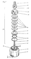
- FIG. 1 An example of such a known clamping device is that commonly used for clamping pallets or fixtures by machining centres.
- This known device comprises a clamping plate intended to be inserted into a substantially T-shaped recess at the bottom of the pallet.
- the clamping plate is firmly connected to a cylinder housing in which a piston is provided which seals against the inner wall of the cylinder housing and which is stationary in relation to the machine table of the machining centre, but which is slidable in relation to the cylinder housing, whereby the cylinder housing and the clamping plate connected thereto are movable up and down in the clamping direction when pressurized fluid is introduced at the upper side and lower side respectively of the piston.
- clamping device of the kind mentioned initially, which eliminates one or some of the above discussed disadvantages.
- This last mentioned, known clamping device is however, designated for a very specific and narrowly delimited range of application since it is adapted for clamping a two-part tool in a press or injection machine or the like. More specifically this means that the clamping device consists of an upper and a lower clamping unit, i.e. one unit for the upper tool and one unit for the lower tool arranged at a distance from the upper tool. It is however possible to use these upper and lower clamping units one by one for other clamping purposes, but even in such a case these suffer from very serious shortcomings and limitations regarding the use thereof.
- said lower clamping unit comprises a holding means consisting of two elongate guide bars, while the clamping means consists of a pin having a head and being connected to the clamping mechanism so that it, when it has been inserted sideways into the groove formed by the guide bars, engages the guide bars with its head when the clamping mechanism is manecuted.
- this lower clamping unit suffers from the disadvantage that the guide bars (which to a great extent correspond to the T-shaped groove in the pallet) render a transportation of the tool on a roll conveyor impossible. Dirt and cuttings may also very easily get stuck in the guide bars so that they prevent clamping. As mentioned above it is also very difficult to perform an effective cleaning of such an elongate guide groove.
- the complete clamping unit, in the clamping position also the guide bars is provided in or below the machine table and this means that it would be very complicated and unacceptably expensive to modify an existing machine tool so that this clamping unit could be employed.
- the upper clamping unit likewise comprises a holding means consisting of two elongate guide bars attached to the rear side of the tool and involving the above discussed disadvantages.
- the clamping means consists of a pin having two opposite projections at its outer end. After the tool has been brought down against the work table, but prior to the application of the clamping force, the clamping means is rotated so that its projections engage the recess or groove of the guide bars, and this is a long known principle for the clamping of work pieces on a work table by means of T-shaped grooves.
- the disadvantage of this solution is that very bulky operation devices are required for rotation of the clamping means.
- US-A-3 461 794 discloses another clamping device of the general type indicated above, for clamping a bolster in position in a press bed.
- This prior art clamping device comprises a clamping mechanism located in and below the press bed and comprising a cylinder housing and a piston slidable in the cylinder housing, said piston carrying a pair of clamping arms and reciprocated by a hydraulic cylinder connected to the piston by a piston rod.
- the bolster intended to be clamped on the press bed is supported on wheels cooperating with guide tracks on the press bed and having annular grooves formed on opposite sides thereof.
- the clamping arms of the clamping mechanism are provided with nose portions adapted to be received in the annular grooves of the wheels for clamping the wheels and thus the bolster on the press bed.
- the nose portions of the clamping arms and the annular grooves on the wheels are also designed so as to provide a centering action during clamping in the event that the bolster is not precisely located on the press bed prior to clamping.
- this known clamping device is designed for performing a certain centering action this centering is far from sufficient for clamping for instance pallets or fixtures in machining centers where clamping often must be performed with an accuracy of a few hundreds of millimeters or less. This is partly due to the fact that the wheels must be journalled with a certain degree of play in order to be rotatable. Moreover the centering is achieved through a certain camming action between the clamping arms and the annular grooves and it is obvious that such a camming action will produce wear on both the clamping arms and the grooves when employing clamping forces of up to 50 tons, thereby excluding the possibility of performing a precise clamping with high repetition accuracy.
- clamping device disclosed in US-A-3 461 794 is of such a structure that it must be provided in and below the press bed, machine table etc. This means that it could not be installed in for instance machine tools where there is no or only limited free space below the machine table, and that, where sufficient space is at hand, extensive modification of the existing machine tool would be required to install the clamping device.
- the object of the present invention is to provide a clamping device of the kind indicated in the introduction, which as far as possible eliminates the above discussed shortcomings of previously known clamping devices, and which also makes it possible to perform a very efficient and precise clamping with high repetition accuracy.
- the clamping device basically consists of a holding means 2 secured in a recess 3 in the figure 1 and shaped as a cylindrical pin having an enlarged head 4 at its end protruding into the recess 3.
- the holding means 2 is in its end facing the fixture provided with an external thread and is screwed into a hole in the fixture which is provided with a corresponding thread.
- the last mentioned end of the holding means 2 is accessible from the upper side of the fixture 1 and is provided with a socket for e.g. an Allen wrench.
- the holding means may easily be adjusted so that a firm locking or clamping may be achieved, and the holding means 2 is preferably fixed in the adjusted position by means of a nut 5.
- the recess 3 in the fixture 1 is preferably circular in cross-section and in the illustrated embodiment it is provided with a tapered shoulder 6 for accurate guiding of the fixture down over the clamping device, and the importance of this guide shoulder 6 will be discussed more closely below.
- the clamping device furthermore consists of the actual clamping mechanism 7 and the clamping means 8 connected thereto.
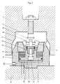
- the clamping means 8 are mounted in a housing 9 which in turn is screwed onto the machine table 10 by means of a number of, preferably four, bolts 11.
- a housing 9 which in turn is screwed onto the machine table 10 by means of a number of, preferably four, bolts 11.
- a preferably circular projection 12 which is fitted into a corresponding recess in the work table 10.
- the outer wall of the housing 9 has such a shape and size that it may be inserted with a slight clearance into the recess 3 of the fixture 1, and it is also provided with a tapered shoulder 13 corresponding to the tapered shoulder 6 of the recess, whereby the shoulders will be sealingly contacting each other in the clamping position.
- the cone angle (angle C) of the shoulders must be smaller than 30° (if the angle is greater there will be no correct centering between the recess and the housing) but not so small that a locking occurs like that achieved by means of a tool cone (this locking effect occurs when the angle is about 10°). It has been found that a preferable cone angle is about 25°.
- the actual clamping mechanism 7 consists of a piston 15 which is slidably provided in a central opening 14 in the housing and which at its circumference is provided with a sealing ring 16 for efficiently sealing against the inner wall of the opening 14.
- the piston 15 is also provided with a piston rod 17 which is formed integral with the piston and around which a number of cup springs 18 are positioned.
- the cup springs 19 are biased against the upper side of the piston 15 by means of a nut 19 screwed into the opening and forming a collar therein.
- a support plate 20 is secured to the upper end of the piston rod 17 by means of a central bolt 21.
- clamping hooks 8 On the upper side of the support plate 20 a number of clamping means in the shape of clamping hooks 8 are pivotally mounted on pins 22. In the illustrated embodiment four clamping hooks 8 are provided which taken in pairs are diametrically opposed to each other so that a self- centering locking is achieved against the head 4 of the cylindrical holding means 2. However, the number of clamping hooks may vary for different applications.
- the clamping hooks are biased outwardly towards their disengaging position by means of springs 23, but their pivotal movement outwards is restricted by a guide surface 24.
- a relatively thin (about 1 mm) washer 23a is interposed between the springs and the lowermost portion of the hooks.
- the rear surface 25 of the clamping hooks which surface cooperates with the guide surface 24, is straight while the guide surface 24 of the nut 19 is provided with a lower vertical portion and an upper portion which is inclined outwardly from the clamping hooks.
- the surfaces 26 and 27 on the clamping hook and on the head 4 of the holding means respectively are shaped with negative angles for obtaining a secure clamping. Moreover these surfaces are preferably shaped in such a way that they form a part of a circle having its centre in the centre of the swinging movement of the clamping hooks. Hereby the clamping hooks may be swung free from the head of the holding means after a very short disengagement distance.
- Preferably hydraulic oil is used for maneuvering the clamping device.
- this hydraulic fluid is conducted to a chamber below the piston 15 from a pressurized fluid source P.
- a booster advantageously may be used in the situations where hydraulic oil cannot be taken directly from the existing hydraulic system in the machine tool.
- 0-rings 29 are preferably arranged around each mounting bolt 11 at the bottom of the housing 9.
- a copper washer 33 is in the illustrated embodiment provided between the central bolt 21 and the piston.
- O-rings or other seals it is also possible to provide O-rings or other seals between the piston rod 17 and the support 20.
- the clamping device In the normal position, i.e. when the chamber below the piston 15 is not pressurized by means of hydraulic oil, the clamping device is in the condition illustrated in Fig. 2 where the clamping hooks 8 are swung into their clamping position.
- a valve (not shown) is switched over and pressurized hydraulic fluid is supplied below the piston 15, whereby the piston 15 is pushed upwardly counteracting the force from the cup springs 18.
- the clamping hooks 8 slide with their rear surfaces 25 continuously engaging the guide surface 24 due to the bias from the springs 23.
- the clamping hooks are consequently swung outwardly to their disengagement position illustrated in Fig.
- the clamping hooks will clamp the fixture against the housing 9 of the clamping device with the full force of the cup springs 18 due to the engagement between their surfaces 26 and the surface 27 of the holding means.
- the mutual positioning of the tapered shoulders 6 and 13 respectively is selected in such a way that the fixture, when clamped is positioned at a distance from the machine table. Hereby. cuttings which may remain on the work table cannot have any negative influence on the clamping.
- clamping force may also be adjusted by using a greater or smaller number of cup springs.
- clamping forces e.g. 100 kilos and up to 50 tons.
- pressurized air is conducted from the spring space and in between the clamping hooks 8.
- pressurized air is conducted from a pressurized air source Q and into the channel 30 simultaneously with the introduction of hydraulic oil below the piston 15 for the disengagement of the clamping device.
- the pressurized air is supplied during the entire clamping operation and initially cleans the space around the clamping hooks 8 in an efficient manner. Due to the fact that the cleaning air is supplied from within the actual clamping mechanism much more effective cleaning of the space is achieved than that achieved if pressurized air from the outside is directed down towards said space.
- a fine oil mist may be supplied together with the pressurized air for simultaneous lubrication of the cup springs and to a certain extent also of the surfaces 24 and 25 of the nut and hooks 8 respectively (hereby friction therebetween is further reduced).
- the valve 32 may be switched over so that pressurized air is trapped in the space between the fixture and the housing of the clamping device. Since the cooperating shoulder surfaces 6, 13 must have a very fine or smooth surface in orderto guarantee the above mentioned great accuracy of the clamping, they will also seal off the space between the fixture and the housing so completely that a certain pressure is maintained therein. This also makes it possible to efficiently control that the clamping has been performed with desired accuracy.
- This control is accomplished by connecting a pressure governor to said space; in the illustrated embodiment this is indicated by means of a pressure gauge 34 connected to the pressure conduit 30.
- a control unit which forms no part of the invention and is therefore not illustrated or described in any detail
Landscapes
- Engineering & Computer Science (AREA)
- Mechanical Engineering (AREA)
- Jigs For Machine Tools (AREA)
- Electrical Discharge Machining, Electrochemical Machining, And Combined Machining (AREA)
Claims (6)
Priority Applications (1)
| Application Number | Priority Date | Filing Date | Title |
|---|---|---|---|
| AT84850118T ATE39075T1 (de) | 1983-04-12 | 1984-04-11 | Spannvorrichtung. |
Applications Claiming Priority (2)
| Application Number | Priority Date | Filing Date | Title |
|---|---|---|---|
| SE8302028A SE440618B (sv) | 1983-04-12 | 1983-04-12 | Fastspenningsanordning, i synnerhet for fastspenning av arbetsbord, fixturer eller liknande pa ett underlag, sasom maskinbordet i en bearbetningsmaskin |
| SE8302028 | 1983-04-12 |
Publications (3)
| Publication Number | Publication Date |
|---|---|
| EP0125220A2 EP0125220A2 (fr) | 1984-11-14 |
| EP0125220A3 EP0125220A3 (en) | 1985-08-28 |
| EP0125220B1 true EP0125220B1 (fr) | 1988-12-07 |
Family
ID=20350767
Family Applications (1)
| Application Number | Title | Priority Date | Filing Date |
|---|---|---|---|
| EP84850118A Expired EP0125220B1 (fr) | 1983-04-12 | 1984-04-11 | Dispositif de serrage |
Country Status (6)
| Country | Link |
|---|---|
| US (1) | US4577847A (fr) |
| EP (1) | EP0125220B1 (fr) |
| JP (1) | JPH0622774B2 (fr) |
| AT (1) | ATE39075T1 (fr) |
| DE (1) | DE3475495D1 (fr) |
| SE (1) | SE440618B (fr) |
Families Citing this family (45)
| Publication number | Priority date | Publication date | Assignee | Title |
|---|---|---|---|---|
| JPS61178648U (fr) * | 1985-04-26 | 1986-11-07 | ||
| EP0212047A3 (fr) * | 1985-07-25 | 1989-04-26 | Fried. Krupp Gesellschaft mit beschränkter Haftung | Vérin de serrage à ressort |
| US4790739A (en) * | 1985-10-08 | 1988-12-13 | Lema S.R.L. | Die and backing block assembly with quick release fastening means |
| US4688974A (en) * | 1985-12-20 | 1987-08-25 | Deere & Company | Cooperating bolster and fixture construction for quick-change fixturing |
| JPS62157754A (ja) * | 1985-12-27 | 1987-07-13 | Tsudakoma Ind Co Ltd | パレツトクランプ装置 |
| US4664366A (en) * | 1986-04-16 | 1987-05-12 | University Of Kansas Center For Research | Fixture arrangement for machine tool work tables |
| US4695047A (en) * | 1986-10-14 | 1987-09-22 | Carr Lane Roemheld Manufacturing Co., Inc. | T-slot hydraulic clamp system |
| DE8704411U1 (de) * | 1987-03-25 | 1987-05-07 | Maschinenfabrik Heid AG, Stockerau | Spannkopf für das lösbare Befestigen eines Werkstückträgers, wie etwa einer Palette eines Futters od.dgl., auf einer Spindel einer Werkzeugmaschine |
| SE466090B (sv) * | 1987-05-07 | 1991-12-16 | 3R Syst Int Ab | Anordning foer loesbar och repeterbar fastspaenning av tvaa foeremaal vid varandra |
| US4948105A (en) * | 1987-11-09 | 1990-08-14 | Kabushiki Kaisha Kosmek | Hydraulic clamp |
| DE3887113T2 (de) * | 1987-11-09 | 1994-04-28 | Kosmek Amagasaki Kk | Hydraulische Spannvorrichtung. |
| JPH01170532A (ja) * | 1987-12-25 | 1989-07-05 | Kosumetsuku:Kk | シリンダ形油圧クランプ |
| US4932642A (en) * | 1988-04-12 | 1990-06-12 | Hines Industries, Inc. | Workpiece support tooling |
| JP2906058B2 (ja) * | 1988-08-23 | 1999-06-14 | 株式会社森精機製作所 | 工作機械のテーブル装置 |
| DE58907292D1 (de) * | 1988-12-12 | 1994-04-28 | Mathys Ag Dipl Ingenieure Eth | Klemmvorrichtung zum temporären Halten eines Gegenstandes auf einer Unterlage. |
| DE4010653A1 (de) * | 1990-04-03 | 1991-10-10 | Lebrecht Horst Dipl Ing Fh | Zentrierende spannvorrichtung |
| JP2929029B2 (ja) * | 1990-06-08 | 1999-08-03 | 株式会社新川 | ボンダ用クランパ装置 |
| DE4135418A1 (de) * | 1991-10-26 | 1993-05-27 | Emil Stark Gmbh | Spannvorrichtung zum spannen einer aufspannplatte auf einer traegerplatte fuer bearbeitungsmaschinen |
| DE4327861A1 (de) * | 1993-08-19 | 1995-02-23 | Bessey & Sohn | Spanneinrichtung |
| DE19636375A1 (de) * | 1996-09-09 | 1998-03-12 | Emil Stark | Schnellverschluß für eine Palette unter Späneflug |
| DE29615613U1 (de) * | 1996-09-09 | 1997-08-28 | Stark, Emil, Götzis | Spannvorrichtung zum Spannen eines Schnellspannzylinders auf einer Trägerplatte für Bearbeitungsmaschinen |
| DE19806961A1 (de) * | 1998-02-19 | 1999-08-26 | Emil Stark | Schnellspannzylinder zum Einziehen und Zentrieren eines Einzugsnippels |
| DE19829955A1 (de) * | 1998-07-04 | 2000-01-05 | System 3R International Ab Vae | Verbinder zur Verwendung in einer Kupplungsvorrichtung |
| US6413113B2 (en) * | 1999-07-14 | 2002-07-02 | Aehr Test Systems | Kinematic coupling |
| US6580283B1 (en) | 1999-07-14 | 2003-06-17 | Aehr Test Systems | Wafer level burn-in and test methods |
| US6340895B1 (en) * | 1999-07-14 | 2002-01-22 | Aehr Test Systems, Inc. | Wafer-level burn-in and test cartridge |
| US6562636B1 (en) | 1999-07-14 | 2003-05-13 | Aehr Test Systems | Wafer level burn-in and electrical test system and method |
| DE10006847C2 (de) * | 2000-02-16 | 2003-09-18 | Vischer & Bolli Ag Duebendorf | Spanneinrichtung |
| JP2002361533A (ja) * | 2001-06-07 | 2002-12-18 | Kosmek Ltd | データム機能付きクランプ装置 |
| US20040018048A1 (en) * | 2002-07-26 | 2004-01-29 | Sausen Earl W. | Pneumatic docking system |
| DE10317337B4 (de) * | 2003-04-15 | 2020-06-10 | Andreas Maier Gmbh & Co. Kg | Schnellspannzylinder in Modulbauweise |
| DE10317349B4 (de) * | 2003-04-15 | 2018-01-25 | Andreas Maier Gmbh & Co. Kg | Kombination aus einemSchnellspannzylinder und einer lagerichtig auf dem selben aufliegenden Werkstückpalette |
| DE10317341B4 (de) * | 2003-04-15 | 2014-03-20 | Andreas Maier Gmbh & Co. Kg | Schnellspannzylinder mit Führungseinrichtung |
| DE10358943A1 (de) * | 2003-12-15 | 2005-07-14 | Fertigungstechnik Weissenfels Gmbh | Werkstücktisch |
| JP4220955B2 (ja) * | 2004-10-29 | 2009-02-04 | ファナック株式会社 | パレットチェンジャのクランプ機構 |
| US20150082584A1 (en) * | 2013-09-25 | 2015-03-26 | Siemens Industry, Inc. | Clamp for rolling mill roll stand |
| CN103551890B (zh) * | 2013-10-16 | 2015-11-25 | 博深工具股份有限公司 | 铰孔定位夹紧装置 |
| US10357859B1 (en) | 2014-03-06 | 2019-07-23 | Daniel J Reed | Clamping system for securing a work piece to a fixture |
| CN105215730B (zh) * | 2015-09-25 | 2017-06-16 | 桐乡市恒泰精密机械有限公司 | 用于偏心轴套打孔和倒角的装置 |
| CN106312341B (zh) * | 2016-11-11 | 2017-12-08 | 北京工业大学 | 用于刀具刃口加工的工装夹具、装置及方法 |
| EP3856452A4 (fr) * | 2018-09-24 | 2022-06-01 | PHD, Inc. | Socle dynamique destiné à la localisation et au maintien d'éléments |
| US10871507B2 (en) * | 2018-12-20 | 2020-12-22 | Texas Instruments Incorporated | Semiconductor device handler with chuck clamp interlock |
| CN113752058A (zh) * | 2021-08-29 | 2021-12-07 | 北京工业大学 | 一种推进器导边随边加工专用柔性夹持工装 |
| CN113843580B (zh) * | 2021-10-21 | 2023-06-30 | 沪东重机有限公司 | 一种阀座加工装夹工装及高精度阀座的加工方法 |
| CN115157152A (zh) * | 2022-08-16 | 2022-10-11 | 深圳安洁电子有限公司 | 一种用于pet材料精雕加工的辅助治具 |
Family Cites Families (14)
| Publication number | Priority date | Publication date | Assignee | Title |
|---|---|---|---|---|
| DE148319C (fr) * | 1902-05-11 | 1904-02-16 | ||
| NL124252C (fr) * | 1963-09-27 | |||
| US3461794A (en) * | 1967-10-13 | 1969-08-19 | Bliss Co | Bolster lift clamp |
| GB1470593A (en) * | 1974-08-09 | 1977-04-14 | Glentore Eng Prod Ltd | Nail extractor |
| SU639681A1 (ru) * | 1977-08-08 | 1978-12-30 | Ордена Трудового Красного Знамени Экспериментальный Научно-Исследовательский Институт Металлорежущих Станков | Устройство дл креплени деталей |
| GB1543119A (en) * | 1977-09-01 | 1979-03-28 | Glentore Eng Prod Ltd | Extractor for nails etc |
| SE423604B (sv) * | 1978-04-18 | 1982-05-17 | Hakan Sallander | Anordning for fastspenning av ett tvadelat verktyg i en maskin sasom en press eller liknande |
| US4275983A (en) * | 1978-07-17 | 1981-06-30 | Bergman Raymond A | Air float fixture clamping system |
| DE3025156C2 (de) * | 1980-07-03 | 1985-04-25 | A. Römheld GmbH & Co KG, 6312 Laubach | Presse mit einem Stanz- und/oder Preßwerkzeug |
| DE3025157A1 (de) * | 1980-07-03 | 1982-01-28 | A. Römheld GmbH & Co KG, 6312 Laubach | Spannelemente, insbesondere zum festspannen von werkstuecken oder werkzeugen auf werkzeugmaschinen |
| JPS5730617A (en) * | 1980-07-31 | 1982-02-18 | Toyota Motor Corp | Automobile power transmission device |
| JPS6031896Y2 (ja) * | 1981-01-20 | 1985-09-24 | 東洋精器株式会社 | ツ−ルプリセツタにおけるツ−ルシヤンクの支持装置 |
| US4496139A (en) * | 1981-04-09 | 1985-01-29 | Kurt Manufacturing Company, Inc. | Vise clamp and swivel base vise using such clamp |
| JPS5822232U (ja) * | 1981-08-04 | 1983-02-10 | 相生精機株式会社 | 工作機械へのクランプパレツト交換装置 |
-
1983
- 1983-04-12 SE SE8302028A patent/SE440618B/sv not_active IP Right Cessation
-
1984
- 1984-04-11 US US06/599,183 patent/US4577847A/en not_active Expired - Lifetime
- 1984-04-11 AT AT84850118T patent/ATE39075T1/de active
- 1984-04-11 DE DE8484850118T patent/DE3475495D1/de not_active Expired
- 1984-04-11 EP EP84850118A patent/EP0125220B1/fr not_active Expired
- 1984-04-12 JP JP59073846A patent/JPH0622774B2/ja not_active Expired - Fee Related
Also Published As
| Publication number | Publication date |
|---|---|
| ATE39075T1 (de) | 1988-12-15 |
| SE8302028L (sv) | 1984-10-13 |
| US4577847A (en) | 1986-03-25 |
| SE8302028D0 (sv) | 1983-04-12 |
| JPH0622774B2 (ja) | 1994-03-30 |
| EP0125220A3 (en) | 1985-08-28 |
| DE3475495D1 (en) | 1989-01-12 |
| EP0125220A2 (fr) | 1984-11-14 |
| JPS6048232A (ja) | 1985-03-15 |
| SE440618B (sv) | 1985-08-12 |
Similar Documents
| Publication | Publication Date | Title |
|---|---|---|
| EP0125220B1 (fr) | Dispositif de serrage | |
| US7303186B2 (en) | Aligning drive mechanism and positioning apparatus having this mechanism | |
| US6527266B1 (en) | Clamping apparatus with datum function | |
| EP0291482B1 (fr) | Dispositif pour fixer un élément à un ancre d'une manière démontable et répétitive | |
| US4380939A (en) | Rotary indexing table | |
| US6170814B1 (en) | Method for attaching a jaw to a vise-like workholding apparatus | |
| CN114131377B (zh) | 一种自动化型零点定位系统以及工件母板 | |
| US10711821B2 (en) | Modular locking pin | |
| US8061717B2 (en) | Positioning and clamping device for tools and/or workpieces | |
| KR100714062B1 (ko) | 로봇용 그립 교환장치 | |
| US4298307A (en) | Air float power rotation system | |
| WO2024070394A1 (fr) | Dispositif de serrage | |
| CN221020714U (zh) | 一种直角定位工装 | |
| US4575062A (en) | Coupling construction and clamp therefor | |
| US5362108A (en) | Automatic pallet fluid coupler | |
| US6478135B1 (en) | Modular palletized work station for asynchronous conveyor systems | |
| CN111451533A (zh) | 锁止设备以及适配器 | |
| CN113620042B (zh) | 一种轴向微调机构及具有微调功能的转盘输送装置 | |
| US5711198A (en) | Vertical lathe workpiece support structure | |
| EP1222046B1 (fr) | Dispositif a commande pneumatique permettant de centrer une piece a usiner dans une machine | |
| CN223588810U (zh) | 一种刀具便于调节的车床 | |
| CN221415773U (zh) | 工件固定装置 | |
| CN115816188A (zh) | 一种共基准偏心孔快速定位系统及其控制方法 | |
| KR200419970Y1 (ko) | 로봇용 그립 교환장치 | |
| JPH07241740A (ja) | パレットのクランプ装置 |
Legal Events
| Date | Code | Title | Description |
|---|---|---|---|
| PUAI | Public reference made under article 153(3) epc to a published international application that has entered the european phase |
Free format text: ORIGINAL CODE: 0009012 |
|
| AK | Designated contracting states |
Designated state(s): AT BE CH DE FR GB IT LI NL SE |
|
| PUAL | Search report despatched |
Free format text: ORIGINAL CODE: 0009013 |
|
| AK | Designated contracting states |
Designated state(s): AT BE CH DE FR GB IT LI NL SE |
|
| 17P | Request for examination filed |
Effective date: 19860204 |
|
| 17Q | First examination report despatched |
Effective date: 19870611 |
|
| GRAA | (expected) grant |
Free format text: ORIGINAL CODE: 0009210 |
|
| AK | Designated contracting states |
Kind code of ref document: B1 Designated state(s): AT BE CH DE FR GB IT LI NL SE |
|
| REF | Corresponds to: |
Ref document number: 39075 Country of ref document: AT Date of ref document: 19881215 Kind code of ref document: T |
|
| REF | Corresponds to: |
Ref document number: 3475495 Country of ref document: DE Date of ref document: 19890112 |
|
| ET | Fr: translation filed | ||
| ITF | It: translation for a ep patent filed | ||
| PLBE | No opposition filed within time limit |
Free format text: ORIGINAL CODE: 0009261 |
|
| STAA | Information on the status of an ep patent application or granted ep patent |
Free format text: STATUS: NO OPPOSITION FILED WITHIN TIME LIMIT |
|
| 26N | No opposition filed | ||
| PG25 | Lapsed in a contracting state [announced via postgrant information from national office to epo] |
Ref country code: FR Free format text: LAPSE BECAUSE OF NON-PAYMENT OF DUE FEES Effective date: 19891228 |
|
| REG | Reference to a national code |
Ref country code: FR Ref legal event code: ST |
|
| REG | Reference to a national code |
Ref country code: FR Ref legal event code: AR |
|
| PGFP | Annual fee paid to national office [announced via postgrant information from national office to epo] |
Ref country code: FR Payment date: 19910424 Year of fee payment: 8 |
|
| ITTA | It: last paid annual fee | ||
| REG | Reference to a national code |
Ref country code: FR Ref legal event code: DI |
|
| EAL | Se: european patent in force in sweden |
Ref document number: 84850118.5 |
|
| PGFP | Annual fee paid to national office [announced via postgrant information from national office to epo] |
Ref country code: NL Payment date: 19990429 Year of fee payment: 16 |
|
| PGFP | Annual fee paid to national office [announced via postgrant information from national office to epo] |
Ref country code: AT Payment date: 19990430 Year of fee payment: 16 |
|
| PGFP | Annual fee paid to national office [announced via postgrant information from national office to epo] |
Ref country code: BE Payment date: 19990517 Year of fee payment: 16 |
|
| PG25 | Lapsed in a contracting state [announced via postgrant information from national office to epo] |
Ref country code: AT Free format text: LAPSE BECAUSE OF NON-PAYMENT OF DUE FEES Effective date: 20000411 |
|
| PG25 | Lapsed in a contracting state [announced via postgrant information from national office to epo] |
Ref country code: BE Free format text: LAPSE BECAUSE OF NON-PAYMENT OF DUE FEES Effective date: 20000430 |
|
| BERE | Be: lapsed |
Owner name: SCHEDWIN SVEN-ERIK Effective date: 20000430 |
|
| PG25 | Lapsed in a contracting state [announced via postgrant information from national office to epo] |
Ref country code: NL Free format text: LAPSE BECAUSE OF NON-PAYMENT OF DUE FEES Effective date: 20001101 |
|
| NLV4 | Nl: lapsed or anulled due to non-payment of the annual fee |
Effective date: 20001101 |
|
| REG | Reference to a national code |
Ref country code: GB Ref legal event code: IF02 |
|
| PGFP | Annual fee paid to national office [announced via postgrant information from national office to epo] |
Ref country code: GB Payment date: 20030409 Year of fee payment: 20 |
|
| PGFP | Annual fee paid to national office [announced via postgrant information from national office to epo] |
Ref country code: SE Payment date: 20030424 Year of fee payment: 20 Ref country code: CH Payment date: 20030424 Year of fee payment: 20 |
|
| PGFP | Annual fee paid to national office [announced via postgrant information from national office to epo] |
Ref country code: DE Payment date: 20030425 Year of fee payment: 20 |
|
| PG25 | Lapsed in a contracting state [announced via postgrant information from national office to epo] |
Ref country code: SE Free format text: LAPSE BECAUSE OF NON-PAYMENT OF DUE FEES Effective date: 20031206 |
|
| PG25 | Lapsed in a contracting state [announced via postgrant information from national office to epo] |
Ref country code: LI Free format text: LAPSE BECAUSE OF EXPIRATION OF PROTECTION Effective date: 20040410 Ref country code: GB Free format text: LAPSE BECAUSE OF EXPIRATION OF PROTECTION Effective date: 20040410 Ref country code: CH Free format text: LAPSE BECAUSE OF EXPIRATION OF PROTECTION Effective date: 20040410 |
|
| REG | Reference to a national code |
Ref country code: CH Ref legal event code: PL |
|
| REG | Reference to a national code |
Ref country code: GB Ref legal event code: PE20 |
|
| EUG | Se: european patent has lapsed |