EP0125328A1 - Pompe à palettes, en particulier pour servo-assistance - Google Patents
Pompe à palettes, en particulier pour servo-assistance Download PDFInfo
- Publication number
- EP0125328A1 EP0125328A1 EP83104769A EP83104769A EP0125328A1 EP 0125328 A1 EP0125328 A1 EP 0125328A1 EP 83104769 A EP83104769 A EP 83104769A EP 83104769 A EP83104769 A EP 83104769A EP 0125328 A1 EP0125328 A1 EP 0125328A1
- Authority
- EP
- European Patent Office
- Prior art keywords
- channel
- valve
- insert
- side end
- vane pump
- Prior art date
- Legal status (The legal status is an assumption and is not a legal conclusion. Google has not performed a legal analysis and makes no representation as to the accuracy of the status listed.)
- Granted
Links
- 230000003628 erosive effect Effects 0.000 claims abstract description 9
- 239000000463 material Substances 0.000 claims abstract description 8
- 239000012530 fluid Substances 0.000 claims description 14
- 230000000694 effects Effects 0.000 claims description 2
- XAGFODPZIPBFFR-UHFFFAOYSA-N aluminium Chemical compound [Al] XAGFODPZIPBFFR-UHFFFAOYSA-N 0.000 description 6
- 229910052782 aluminium Inorganic materials 0.000 description 6
- 238000004512 die casting Methods 0.000 description 3
- 230000007704 transition Effects 0.000 description 3
- 229910001369 Brass Inorganic materials 0.000 description 2
- 239000010951 brass Substances 0.000 description 2
- 238000009826 distribution Methods 0.000 description 2
- 238000000034 method Methods 0.000 description 2
- 229910000906 Bronze Inorganic materials 0.000 description 1
- 229910000831 Steel Inorganic materials 0.000 description 1
- 230000015572 biosynthetic process Effects 0.000 description 1
- 239000010974 bronze Substances 0.000 description 1
- 238000005266 casting Methods 0.000 description 1
- KUNSUQLRTQLHQQ-UHFFFAOYSA-N copper tin Chemical compound [Cu].[Sn] KUNSUQLRTQLHQQ-UHFFFAOYSA-N 0.000 description 1
- 230000003247 decreasing effect Effects 0.000 description 1
- 238000001125 extrusion Methods 0.000 description 1
- 238000004519 manufacturing process Methods 0.000 description 1
- 238000009991 scouring Methods 0.000 description 1
- 238000007789 sealing Methods 0.000 description 1
- 239000010959 steel Substances 0.000 description 1
- 238000003860 storage Methods 0.000 description 1
Images

Classifications
-
- F—MECHANICAL ENGINEERING; LIGHTING; HEATING; WEAPONS; BLASTING
- F04—POSITIVE - DISPLACEMENT MACHINES FOR LIQUIDS; PUMPS FOR LIQUIDS OR ELASTIC FLUIDS
- F04C—ROTARY-PISTON, OR OSCILLATING-PISTON, POSITIVE-DISPLACEMENT MACHINES FOR LIQUIDS; ROTARY-PISTON, OR OSCILLATING-PISTON, POSITIVE-DISPLACEMENT PUMPS
- F04C15/00—Component parts, details or accessories of machines, pumps or pumping installations, not provided for in groups F04C2/00 - F04C14/00
- F04C15/06—Arrangements for admission or discharge of the working fluid, e.g. constructional features of the inlet or outlet
- F04C15/062—Arrangements for supercharging the working space
-
- F—MECHANICAL ENGINEERING; LIGHTING; HEATING; WEAPONS; BLASTING
- F04—POSITIVE - DISPLACEMENT MACHINES FOR LIQUIDS; PUMPS FOR LIQUIDS OR ELASTIC FLUIDS
- F04C—ROTARY-PISTON, OR OSCILLATING-PISTON, POSITIVE-DISPLACEMENT MACHINES FOR LIQUIDS; ROTARY-PISTON, OR OSCILLATING-PISTON, POSITIVE-DISPLACEMENT PUMPS
- F04C15/00—Component parts, details or accessories of machines, pumps or pumping installations, not provided for in groups F04C2/00 - F04C14/00
Definitions
- the invention relates to a vane pump with the features of the preamble of claim 1.
- supply channels are provided which extend from an oil storage space to the work spaces and each have a normally vertical section and a normally horizontal, knee-shaped section, which are located in the axial plane of the rotor extend and open with their axial legs in current distribution spaces to the work spaces and with their radial legs in a valve chamber from which - when a valve responds - the hydraulic fluid flows out.
- the feed channels are essentially symmetrical and arranged. In the exemplary embodiment shown, the knee-shaped sections of the feed channels have been produced using the casting process.
- the invention is therefore based on the object of designing a vane pump of the type specified at the outset in such a way that there is a good deflection of the hydraulic fluid in the region of the knee-shaped section, the risk of erosion being avoided.
- the erosion is avoided in that the stopper-shaped insert is thicker than the feed channel in the region of the knee-shaped section and to a certain extent lines the feed channel.
- the housing is made of die-cast aluminum, brass or some other less eroding material is used for the plug-shaped use. The transition between the supply channel section formed by the wall of the die-cast aluminum and the knee-shaped section formed by the plug-shaped insert has been moved to a position which is not hit by the jet of hydraulic fluid flowing out of the valve.
- the plug-shaped insert expediently extends up to the inflow channel coming from the tank, in which suction prevails when the valve responds.
- the first or front step of the stepped bore intersects the suction inflow channel.
- the front end of the plug-shaped insert is accessible for a special adapted processing so that the flow conditions at the transition of the discharge channel of the valve to the suction-inflow channel and further into the curved feed channel can be adapted to a wide range of operating conditions.
- the vane pump has a main housing part 1 and a housing cover 2, which are made of die-cast aluminum and enclose an interior 1a in a pressure-tight manner.
- a rotor 7 is arranged within the cam ring 5 and between the housing cover 2 and the pressure plate 4 and has a series of radial guide slots. Wings 8 are radially displaceably mounted within these guide slots.
- the rotor 7 can be driven via a shaft / which is mounted in a bearing bore in the housing cover 2.
- the rotor 7 is cylindrical in shape, while the cam ring 5 has an approximately oval inner contour, the small axis of which corresponds approximately to the diameter of the rotor 7, while the large axis determines the extension length of the vanes 8.
- the cam ring 5 and the rotor 7 there are two crescent-shaped working areas which are divided by the vanes 8 into a number of cell spaces.
- On the suction side of the Sy The cell spaces are constantly increasing and the pressure side is decreasing.
- the supply of hydraulic fluid takes place from a tank (not shown) into a distribution space 16, from which two approximately vertical bores emanate as feed channels 17a, 17b and tangentially meet knee-shaped feed channel sections 18a, 18b, the feed channel sections 18a, 18b in the normally horizontal axis plane of the pump and are arranged symmetrically to each other.
- the knee-shaped feed channel sections 18a, 18b each have a radial leg which opens into an unloading channel 19a or 19b, while the axial legs meet through openings 20 of the pressure plate 4.
- the through openings 20 serve to supply the hydraulic fluid into the respective working spaces of the pump.
- the hydraulic fluid is discharged via channels 33 through the pressure plate 4 on its rear side into a pressure chamber 35 and from there via a delivery channel 36 to an outer pump outlet 37.
- a throttle body 38 with a measuring orifice 38a and an auxiliary throttle 38b.
- the auxiliary throttle 38b is connected to the spring chamber 47 of a flow control valve 40 via a channel 39.
- This has a slide piston 41, which is pushed by the force of a spring 42 in the direction of the back of the pressure plate 4.
- the slide piston 41 has two collar-shaped sealing areas 43 and 44, between which an annular groove 45 extends.
- a channel 46 which extends partially radially and partially axially, leads through the slide piston 41 into the valve chamber 47, and the channel 46 is controlled by a cone valve, which when a certain permissible pressure in the valve space 47 is exceeded responds and vented this space so that the spool 41 acts as a controlled pressure relief valve, as is known.
- the valve 40 assumes the position shown in FIG. 2.
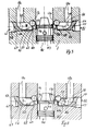
- a gap is released between the piston collar 43 and the edge of the channel 19a or 19b, through which a powerful hydraulic jet 50 (FIGS. 3 to 5) shoots, depending on the pressure of the hydraulic fluid in the pressure chamber 35.
- the jet 50 normally passes obliquely at the mouth of the inflow channel 17a or 17b, so that a suction is created at this junction, through which hydraulic fluid is drawn in from the tank.
- the jet 50 also has the unpleasant property of scouring out the wall material at the point of impact.
- the usual aluminum die-cast material for bearing housings is particularly sensitive to cavitation erosion. In the invention, therefore, the impact point is lined with erosion-resistant material, for example made of brass (in particular material no. 20550), bronze or steel.
- a plug-shaped insert 51 (FIG. 3), 52 (FIG. 4) or 53 (FIG. 5) is provided, which is to be fastened in an associated stepped bore 61 or 62 or 63.
- Each step bore 61, 62, 63 has a front step 64, a middle step 65 or 66 and a rear step 67, from which an outer bore section 68 extends, which, as seen from the valve 40, radially outside the knee-shaped feed channels 18a and 18b is arranged.
- the inserts 51, 52, 53 each have a press collar 54 with a conical taper 55 in order to insert the bore section 68 and to hold it by a press fit.
- In each middle part of the insert there is a toroidal deflection section 56 along a quarter circle provided on which the flow deflection between the radial and axial leg of the knee-shaped feed channel 18a or 18b takes place.
- the front steps 64, 65 are arranged near the center of the inflow channel 17a or 17b, i.e. the plug-shaped insert 51 has a front end 57 which is drawn very far inward and which is cut out in the region of the inflow channel 17a, 17b in order not to hinder the inflow of hydraulic fluid.
- the deflection channel is designed as a laterally open groove which extends at the valve-side end 57 in the axial direction of the insert 51 and is designed as a torus at the pump-side end 58. Such a groove can easily be made with a ball mill.
- the diameter of the unloading channel 19a, 19b is smaller than the groove depth of the insert 51, i.e.
- FIG. 4 also shows an insert 52 which extends far inwards, the front end 57 of which is designed similarly to that in FIG . This is possible because the pump-side end 58 of the deflection channel is quite easily accessible and a ball mill can be guided along a curve when immersed in the insert 52 to be produced.
- the ridge 57g can be be rounded off to reduce the risk of eddy formation.
- the rounded degree 57g lies approximately in the radial central plane of the inflow channel 17a or 17b.
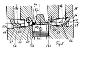
- the insert 53 according to FIG. 5 is somewhat shorter and has a drilled deflection channel, which is produced similarly to the case in FIG. 4.
- the transition point between insert 53 and the die-cast material of the pump housing at stage 66 is particularly at risk of erosion; for this reason it is ensured that the hydraulic jet 50 does not occasionally hit this point.
- the collar 43 has an undercut 43a which is designed in the shape of a flute in order to effect beam guidance in cooperation with the edge 61k.
- the beam 50 is oriented much more parallel to the local axial direction of the channel 19a or 19b than is the case in the embodiment according to FIG. 3 or 4. Therefore, the beam 50 hits the wall of the insert 53 much later, practically in the region of curvature of the deflection channel.
- the insert 51 is preferably produced by extrusion, while the inserts 52 and 53 are preferably drilled and milled in combination, insofar as the deflection channel is produced.
- the housing 1, which is preferably made of aluminum, can also be produced by die casting in addition to die casting.
Landscapes
- Engineering & Computer Science (AREA)
- Mechanical Engineering (AREA)
- General Engineering & Computer Science (AREA)
- Chemical & Material Sciences (AREA)
- Combustion & Propulsion (AREA)
- Rotary Pumps (AREA)
- Details And Applications Of Rotary Liquid Pumps (AREA)
Priority Applications (6)
| Application Number | Priority Date | Filing Date | Title |
|---|---|---|---|
| EP83104769A EP0125328B1 (fr) | 1983-05-14 | 1983-05-14 | Pompe à palettes, en particulier pour servo-assistance |
| DE8383104769T DE3370058D1 (en) | 1983-05-14 | 1983-05-14 | Vane pump, especially for power steering |
| US06/609,290 US4575314A (en) | 1983-05-14 | 1984-05-11 | Deflecting insert for a rotary vane pump |
| CA000454154A CA1217387A (fr) | 1983-05-14 | 1984-05-11 | Pompe centrifuge |
| JP59096296A JPH0689748B2 (ja) | 1983-05-14 | 1984-05-14 | 回転羽根ポンプ |
| JP5086627A JPH0658267A (ja) | 1983-05-14 | 1993-04-14 | 回転羽根ポンプ |
Applications Claiming Priority (1)
| Application Number | Priority Date | Filing Date | Title |
|---|---|---|---|
| EP83104769A EP0125328B1 (fr) | 1983-05-14 | 1983-05-14 | Pompe à palettes, en particulier pour servo-assistance |
Publications (2)
| Publication Number | Publication Date |
|---|---|
| EP0125328A1 true EP0125328A1 (fr) | 1984-11-21 |
| EP0125328B1 EP0125328B1 (fr) | 1987-03-04 |
Family
ID=8190465
Family Applications (1)
| Application Number | Title | Priority Date | Filing Date |
|---|---|---|---|
| EP83104769A Expired EP0125328B1 (fr) | 1983-05-14 | 1983-05-14 | Pompe à palettes, en particulier pour servo-assistance |
Country Status (5)
| Country | Link |
|---|---|
| US (1) | US4575314A (fr) |
| EP (1) | EP0125328B1 (fr) |
| JP (2) | JPH0689748B2 (fr) |
| CA (1) | CA1217387A (fr) |
| DE (1) | DE3370058D1 (fr) |
Cited By (4)
| Publication number | Priority date | Publication date | Assignee | Title |
|---|---|---|---|---|
| DE3506458A1 (de) * | 1984-04-06 | 1985-10-17 | Zahnradfabrik Friedrichshafen | Hochdruckpumpe mit stromregelventil |
| WO1993010354A1 (fr) * | 1991-11-23 | 1993-05-27 | Luk Fahrzeug-Hydraulik Gmbh & Co. Kg | Pompe |
| WO1998059172A1 (fr) * | 1997-06-24 | 1998-12-30 | Luk Fahrzeug-Hydraulik Gmbh & Co. Kg | Pompe pour refouler une substance |
| DE19513079C2 (de) * | 1995-04-07 | 2003-03-27 | Zahnradfabrik Friedrichshafen | Flügelzellenpumpe mit Stromregelventil |
Families Citing this family (7)
| Publication number | Priority date | Publication date | Assignee | Title |
|---|---|---|---|---|
| JPH0634634Y2 (ja) * | 1987-11-09 | 1994-09-07 | カヤバ工業株式会社 | ベーンポンプ |
| JPH02139386U (fr) * | 1989-04-24 | 1990-11-21 | ||
| DE4237483C2 (de) * | 1992-11-06 | 2000-12-07 | Zahnradfabrik Friedrichshafen | Hochdruckpumpe, insbesondere für Hilfskraftlenkungen |
| US5567125A (en) * | 1995-01-06 | 1996-10-22 | Trw Inc. | Pump assembly with tubular bypass liner with at least one projection |
| DE19810318B4 (de) * | 1997-03-12 | 2014-01-16 | Ixetic Bad Homburg Gmbh | Hydraulikmaschine |
| WO2004007966A1 (fr) * | 2002-06-13 | 2004-01-22 | Toyoda Koki Kabushiki Kaisha | Pompe a huile |
| JP4932670B2 (ja) * | 2007-10-25 | 2012-05-16 | カヤバ工業株式会社 | 可変減衰弁 |
Citations (4)
| Publication number | Priority date | Publication date | Assignee | Title |
|---|---|---|---|---|
| US2724335A (en) * | 1951-12-14 | 1955-11-22 | Eaton Mfg Co | Pumping unit with flow director |
| US3366065A (en) * | 1967-01-03 | 1968-01-30 | Chrysler Corp | Supercharging of balanced hydraulic pump |
| FR2075779A5 (fr) * | 1970-01-24 | 1971-10-08 | Zahnradfabrik Friedrichshafen | |
| DE2219588A1 (de) * | 1972-04-21 | 1973-10-25 | Teves Gmbh Alfred | Verfahren und vorrichtung zur herstellung von druckmittelkanaelen in gussgehaeusen von hydromaschinen |
Family Cites Families (4)
| Publication number | Priority date | Publication date | Assignee | Title |
|---|---|---|---|---|
| US2880674A (en) * | 1953-09-11 | 1959-04-07 | Vickers Inc | Power transmission |
| US4168033A (en) * | 1977-07-06 | 1979-09-18 | Rain Bird Sprinkler Mfg. Corp. | Two-piece wear-resistant spray nozzle construction |
| DE3018650A1 (de) * | 1980-05-16 | 1981-11-26 | Zahnradfabrik Friedrichshafen Ag, 7990 Friedrichshafen | Hochdruckpumpe mit einem stomregelventil |
| US4470768A (en) * | 1983-01-03 | 1984-09-11 | Sperry Vickers Zweigniederlassung Der Sperry Gmbh | Rotary vane pump, in particular for assisted steering |
-
1983
- 1983-05-14 EP EP83104769A patent/EP0125328B1/fr not_active Expired
- 1983-05-14 DE DE8383104769T patent/DE3370058D1/de not_active Expired
-
1984
- 1984-05-11 US US06/609,290 patent/US4575314A/en not_active Ceased
- 1984-05-11 CA CA000454154A patent/CA1217387A/fr not_active Expired
- 1984-05-14 JP JP59096296A patent/JPH0689748B2/ja not_active Expired - Lifetime
-
1993
- 1993-04-14 JP JP5086627A patent/JPH0658267A/ja active Pending
Patent Citations (4)
| Publication number | Priority date | Publication date | Assignee | Title |
|---|---|---|---|---|
| US2724335A (en) * | 1951-12-14 | 1955-11-22 | Eaton Mfg Co | Pumping unit with flow director |
| US3366065A (en) * | 1967-01-03 | 1968-01-30 | Chrysler Corp | Supercharging of balanced hydraulic pump |
| FR2075779A5 (fr) * | 1970-01-24 | 1971-10-08 | Zahnradfabrik Friedrichshafen | |
| DE2219588A1 (de) * | 1972-04-21 | 1973-10-25 | Teves Gmbh Alfred | Verfahren und vorrichtung zur herstellung von druckmittelkanaelen in gussgehaeusen von hydromaschinen |
Cited By (9)
| Publication number | Priority date | Publication date | Assignee | Title |
|---|---|---|---|---|
| DE3506458A1 (de) * | 1984-04-06 | 1985-10-17 | Zahnradfabrik Friedrichshafen | Hochdruckpumpe mit stromregelventil |
| WO1993010354A1 (fr) * | 1991-11-23 | 1993-05-27 | Luk Fahrzeug-Hydraulik Gmbh & Co. Kg | Pompe |
| US5496152A (en) * | 1991-11-23 | 1996-03-05 | Luk Farhzeug-Hydraulik Gmbh & Co. Kg | Pump with internal valve between suction and pressure regions |
| DE19513079C2 (de) * | 1995-04-07 | 2003-03-27 | Zahnradfabrik Friedrichshafen | Flügelzellenpumpe mit Stromregelventil |
| DE19513079B9 (de) * | 1995-04-07 | 2004-09-09 | Zf Friedrichshafen Ag | Flügelzellenpumpe mit Stromregelventil |
| WO1998059172A1 (fr) * | 1997-06-24 | 1998-12-30 | Luk Fahrzeug-Hydraulik Gmbh & Co. Kg | Pompe pour refouler une substance |
| GB2332482A (en) * | 1997-06-24 | 1999-06-23 | Luk Fahrzeug Hydraulik | Pump for conveying a medium |
| US6164922A (en) * | 1997-06-24 | 2000-12-26 | Luk Fahrzeug-Hydraulik Gmbh & Co. Kg | Flow control valve for a pump for conveying a medium |
| GB2332482B (en) * | 1997-06-24 | 2001-10-03 | Luk Fahrzeug Hydraulik | Pump for conveying a medium |
Also Published As
| Publication number | Publication date |
|---|---|
| JPH0658267A (ja) | 1994-03-01 |
| EP0125328B1 (fr) | 1987-03-04 |
| CA1217387A (fr) | 1987-02-03 |
| DE3370058D1 (en) | 1987-04-09 |
| JPS59218379A (ja) | 1984-12-08 |
| JPH0689748B2 (ja) | 1994-11-14 |
| US4575314A (en) | 1986-03-11 |
Similar Documents
| Publication | Publication Date | Title |
|---|---|---|
| DE2526175A1 (de) | Einrichtung zum veraendern der volumetrischen kapazitaet eines parallel- und aussenachsigen rotationskolbenverdichters mit kaemmeingriff | |
| DE4428667C2 (de) | Kombiniertes Stromregel- und Druckregelventil für eine Pumpe und mit patronenförmigem Ventilgehäuse | |
| EP0125328B1 (fr) | Pompe à palettes, en particulier pour servo-assistance | |
| DE4446350A1 (de) | Spiralkompressor | |
| EP0030336B1 (fr) | Valve de réglage de pression, en particulier valve de réduction de la pression | |
| DE881306C (de) | Kreiselpumpe mit Spaltringschuetze | |
| DE3532602C2 (de) | Strömungssteuerventil | |
| DE1947117B2 (de) | Verfahren zum herstellen eines ventilschiebers | |
| EP0200182A2 (fr) | Vanne-pilote hydraulique du type robinet à piston | |
| EP0151657A1 (fr) | Pompe à palettes, en particulier pour système de puissance assisté | |
| DE2418275A1 (de) | Pumpvorrichtung | |
| DE2852852B1 (de) | Kolbenpumpe,insbesondere Radialkolbenpumpe | |
| DE2038086C3 (de) | Axialkolbenmaschine | |
| DE1812251A1 (de) | Zellen- bzw. Drehschieberpumpe | |
| DE855363C (de) | Selbstansaugende Umlaufpumpe | |
| DE4438696A1 (de) | Flügelzellenpumpe | |
| DE1528717B2 (de) | Vorrichtung zum ausgleich des axialschubes bei mehrstufigen kreiselpumpen | |
| WO1998026186A1 (fr) | Distributeur pour la commande, independante de la charge, d'un consommateur hydraulique au niveau du sens et de la vitesse | |
| EP0199833B1 (fr) | Pompe hydraulique | |
| DE3005643C2 (de) | Notspeiseanlage für einen Dampferzeuger | |
| EP0068035B1 (fr) | Pompe à palettes en particulier pour direction assistée | |
| DE102016109106A1 (de) | Räumwerkzeug und Werkzeugvorrichtung mit einem Räumwerkzeug | |
| DE1528615A1 (de) | Hydrostatische Radialkolbeneinheit | |
| EP0153968B1 (fr) | Pompe pour direction assistée | |
| DE102014202411A1 (de) | Elektrisch angesteuertes Druckregelventil für eine verstellbare hydrostatische Pumpe und eine verstellbare hydrostatische Pumpe mit einem Druckregelventil |
Legal Events
| Date | Code | Title | Description |
|---|---|---|---|
| PUAI | Public reference made under article 153(3) epc to a published international application that has entered the european phase |
Free format text: ORIGINAL CODE: 0009012 |
|
| AK | Designated contracting states |
Designated state(s): DE FR GB IT SE |
|
| 17P | Request for examination filed |
Effective date: 19850416 |
|
| 17Q | First examination report despatched |
Effective date: 19860318 |
|
| RAP1 | Party data changed (applicant data changed or rights of an application transferred) |
Owner name: VICKERS SYSTEMS GMBH |
|
| ITF | It: translation for a ep patent filed | ||
| GRAA | (expected) grant |
Free format text: ORIGINAL CODE: 0009210 |
|
| AK | Designated contracting states |
Kind code of ref document: B1 Designated state(s): DE FR GB IT SE |
|
| REF | Corresponds to: |
Ref document number: 3370058 Country of ref document: DE Date of ref document: 19870409 |
|
| ET | Fr: translation filed | ||
| PLBE | No opposition filed within time limit |
Free format text: ORIGINAL CODE: 0009261 |
|
| STAA | Information on the status of an ep patent application or granted ep patent |
Free format text: STATUS: NO OPPOSITION FILED WITHIN TIME LIMIT |
|
| 26N | No opposition filed | ||
| REG | Reference to a national code |
Ref country code: GB Ref legal event code: 732 |
|
| ITPR | It: changes in ownership of a european patent |
Owner name: CESSIONE;LUK FAHRZEUG - HIDRAULIK GMBH & CO. KG |
|
| REG | Reference to a national code |
Ref country code: FR Ref legal event code: TP |
|
| ITTA | It: last paid annual fee | ||
| EAL | Se: european patent in force in sweden |
Ref document number: 83104769.1 |
|
| PGFP | Annual fee paid to national office [announced via postgrant information from national office to epo] |
Ref country code: SE Payment date: 19950420 Year of fee payment: 13 |
|
| PG25 | Lapsed in a contracting state [announced via postgrant information from national office to epo] |
Ref country code: SE Effective date: 19960515 |
|
| EUG | Se: european patent has lapsed |
Ref document number: 83104769.1 |
|
| PGFP | Annual fee paid to national office [announced via postgrant information from national office to epo] |
Ref country code: GB Payment date: 20010426 Year of fee payment: 19 |
|
| PGFP | Annual fee paid to national office [announced via postgrant information from national office to epo] |
Ref country code: FR Payment date: 20010518 Year of fee payment: 19 |
|
| PGFP | Annual fee paid to national office [announced via postgrant information from national office to epo] |
Ref country code: DE Payment date: 20010613 Year of fee payment: 19 |
|
| REG | Reference to a national code |
Ref country code: GB Ref legal event code: IF02 |
|
| PG25 | Lapsed in a contracting state [announced via postgrant information from national office to epo] |
Ref country code: GB Free format text: LAPSE BECAUSE OF NON-PAYMENT OF DUE FEES Effective date: 20020514 |
|
| PG25 | Lapsed in a contracting state [announced via postgrant information from national office to epo] |
Ref country code: DE Free format text: LAPSE BECAUSE OF NON-PAYMENT OF DUE FEES Effective date: 20021203 |
|
| GBPC | Gb: european patent ceased through non-payment of renewal fee |
Effective date: 20020514 |
|
| PG25 | Lapsed in a contracting state [announced via postgrant information from national office to epo] |
Ref country code: FR Free format text: LAPSE BECAUSE OF NON-PAYMENT OF DUE FEES Effective date: 20030131 |
|
| REG | Reference to a national code |
Ref country code: FR Ref legal event code: ST |