EP0125540A2 - Dispositif de fabrication de tubes pourvus de trous dans leur paroi - Google Patents
Dispositif de fabrication de tubes pourvus de trous dans leur paroi Download PDFInfo
- Publication number
- EP0125540A2 EP0125540A2 EP84104663A EP84104663A EP0125540A2 EP 0125540 A2 EP0125540 A2 EP 0125540A2 EP 84104663 A EP84104663 A EP 84104663A EP 84104663 A EP84104663 A EP 84104663A EP 0125540 A2 EP0125540 A2 EP 0125540A2
- Authority
- EP
- European Patent Office
- Prior art keywords
- punching
- mandrel
- workpieces
- workpiece
- guide half
- Prior art date
- Legal status (The legal status is an assumption and is not a legal conclusion. Google has not performed a legal analysis and makes no representation as to the accuracy of the status listed.)
- Granted
Links
Images


Classifications
-
- B—PERFORMING OPERATIONS; TRANSPORTING
- B21—MECHANICAL METAL-WORKING WITHOUT ESSENTIALLY REMOVING MATERIAL; PUNCHING METAL
- B21D—WORKING OR PROCESSING OF SHEET METAL OR METAL TUBES, RODS OR PROFILES WITHOUT ESSENTIALLY REMOVING MATERIAL; PUNCHING METAL
- B21D28/00—Shaping by press-cutting; Perforating
- B21D28/24—Perforating, i.e. punching holes
- B21D28/28—Perforating, i.e. punching holes in tubes or other hollow bodies
-
- B—PERFORMING OPERATIONS; TRANSPORTING
- B21—MECHANICAL METAL-WORKING WITHOUT ESSENTIALLY REMOVING MATERIAL; PUNCHING METAL
- B21C—MANUFACTURE OF METAL SHEETS, WIRE, RODS, TUBES, PROFILES OR LIKE SEMI-MANUFACTURED PRODUCTS OTHERWISE THAN BY ROLLING; AUXILIARY OPERATIONS USED IN CONNECTION WITH METAL-WORKING WITHOUT ESSENTIALLY REMOVING MATERIAL
- B21C37/00—Manufacture of metal sheets, rods, wire, tubes, profiles or like semi-manufactured products, not otherwise provided for; Manufacture of tubes of special shape
- B21C37/06—Manufacture of metal sheets, rods, wire, tubes, profiles or like semi-manufactured products, not otherwise provided for; Manufacture of tubes of special shape of tubes or metal hoses; Combined procedures for making tubes, e.g. for making multi-wall tubes
- B21C37/15—Making tubes of special shape; Making tube fittings
-
- Y—GENERAL TAGGING OF NEW TECHNOLOGICAL DEVELOPMENTS; GENERAL TAGGING OF CROSS-SECTIONAL TECHNOLOGIES SPANNING OVER SEVERAL SECTIONS OF THE IPC; TECHNICAL SUBJECTS COVERED BY FORMER USPC CROSS-REFERENCE ART COLLECTIONS [XRACs] AND DIGESTS
- Y10—TECHNICAL SUBJECTS COVERED BY FORMER USPC
- Y10T—TECHNICAL SUBJECTS COVERED BY FORMER US CLASSIFICATION
- Y10T83/00—Cutting
- Y10T83/04—Processes
- Y10T83/0596—Cutting wall of hollow work
Definitions
- the invention relates to a method for producing pipes perforated in the lateral surface.
- a method of the type just mentioned is known, which is used to manufacture silencer tubes.
- the hole pattern desired for the later pipes is punched into a flat metal band.
- the strip is then shaped into tubes, for example using the roll forming method, and welded with a longitudinal seam.
- the pipes are cut to length after welding with the aid of a cutting device that works in relation to the hole pattern.
- the known method has some disadvantages. Since a continuous strip of material is required to introduce the welding energy on both sides of the weld, the rows of holes cannot be evenly distributed around the circumference.
- the known method is relatively complex and inflexible. Small quantities cannot be produced to cover costs.
- a non-generic device for punching roller bearing cages is known.
- the cages each have the shape of a truncated cone. Rectangular recesses are punched into the lateral surface.
- the punching tool is inserted into the cage blanks from the inside and pressed outwards.
- the cages are held on the outside by a holding element.
- the known device is only suitable for workpieces that can be machined from the side and have such an opening width that the tools for machining can be inserted from the outside into the workpiece interior, while at the same time the actuating device for the workpieces remains essentially outside.
- the angular inclination of the outer surface of the workpieces to the body axis makes this machining even easier, since the tools can then get into the interior of the workpieces through the respective further body opening.
- Pipes with an essentially constant and relatively narrow cross-section cannot be perforated on the known device, since the tools can at most operate in the area of the pipe openings, but not in the axial central area of the pipes.
- the invention has for its object to provide a method and an apparatus of the type mentioned which, in addition to the advantage of economical production, offer the possibility of perforating pipes in their outer surface over their entire axial extent and over their entire circumference.
- This object is achieved in that a support element is inserted into the tube and pressed from the inside against the tube and subsequently the tube area acted upon by the support element is perforated from the outside.
- the method according to the invention is simple and offers various advantages. It is equally suitable for seamless pipes and those with seams.
- the latter are formed and welded before punching. Regardless of the hole design, shaping and welding can be optimized in the respective workflow.
- the tubes can be made in stock for common diameters. For the special design of the pipes, it is then sufficient to determine the pipe length and to determine the hole pattern.
- the manufacturer gains great freedom of disposition and is flexible in the recycling of the prefabricated pipes.
- the process can be used economically for both large and small quantities. This is a decisive factor in cost accounting. Reorders for smaller quantities can be processed just as economically as bulk orders, since pre-made pipe blanks can also be used for reorders, which are only provided with the desired hole pattern after knowledge of the order.
- the invention provides the decisive advantage that the tube can be perforated over its entire circumference.
- the hole pattern can extend over the weld seam without interruption.
- the welded connection no longer needs to be taken into account.
- Fully axisymmetric hole patterns can be created.
- Perforated pipes of the type mentioned are usually also used as silencer pipes. The damping properties are increased by the symmetrical hole design.
- the invention it is also possible to punch seamless tubes without difficulty. There is no need to fear that the tubes will lose their cross-sectional shape during perforation.
- the hole pattern can be set as desired.
- the weight-free seamless aluminum tubes can be used especially for silencer tubes.
- the invention provides a device for producing perforated, axially symmetrical workpieces in the lateral surface with a punching tool and a holding element arranged on the outside of the workpiece.
- the support element on the inside of the pipe serves to support the pipe to be punched during the punching process. It holds the pipe tight and tensions it. It also secures the pipe against unwanted evasive movements during processing.
- the pressure mandrel presses the support elements outwards during processing and in turn holds the support element in the working position.
- the invention is suitable for pipes with and without seam and with any possible cross-sectional shape. However, it will primarily be used for pipes with a circular cross-section.
- the paired arrangement of the support elements and the associated punching tools offers the advantage that the punching forces act against one another, so that the support elements and the mandrel and any other parts which are still acted upon by the forces during machining are not loaded on one side.
- the support element is designed as a die containing a hole pattern.
- the hole pattern can either have a predetermined hole pattern depending on the workpiece or be in the form of a surface pattern that contains all possible hole positions.
- the design of the support element as a perforated die facilitates the punching process. The punch waste can be pushed through the die.
- each support element has a sawtooth-like inner surface, which is assigned a sawtooth-like, outwardly directed counter surface on the pressing mandrel. If you move the pressure mandrel relative to the support element, the opposing saw teeth of the support element and the pressure mandrel run against each other.
- each support element is pressed radially outward against the pipe to be machined during an axial movement of the mandrel.
- the loosening takes place in the other order, in that the saw teeth slide off one another and the support element can thereby move away from the workpiece.
- Each support element is advantageously arranged in the interior of a guide half-shell open towards the workpiece, which is formed by the holding element.
- the guide shell complements the support element.
- the workpiece is located between these two parts. It is held in between.
- the guide half-shells can be designed so that they are suitable for holding pipes of different cross-sectional shape and diameter.
- the holding element supports the workpiece at least in the machining area, that is to say in the present case primarily along a pipe surface line.
- the flat design of the holding element is sufficient for this.
- its shape can also be adapted to the workpiece in such a way that it rests on the workpiece outside of the machining area.
- a simple mounting of the support elements results from the fact that they are held at the upper end of the respective guide half-shell. In this way, the workpieces can be inserted from below between the support elements and the guide half-shells.
- the guide half-shells are provided with guide bores for receiving the stamps. Since the guide half-shells are arranged directly next to the workpiece during machining, they are able to hold and guide the punches of the punching tool exactly.
- a simple shape of the punching tool results when the punches are arranged one above the other, primarily along a surface line of the guide half-shells. As a result, the punches can also attack the workpieces along a surface line. This means that it is sufficient to clamp the workpiece between the support element and the guide half-shells along said surface line.
- stamps are assigned a common actuating element.
- an activation bar can be provided in the actuating element, which only connects those punches with the actuating element that are actually to be used for processing the workpiece in question.
- Other stamps which are present in the punching tool, but which are not used in the workpiece to be machined, are not linked to the actuating element by the activation bars and therefore do not take part in the machining. They remain on standby.
- the actuating elements of two or more punching tools have a common feed drive exhibit.
- the feed drive comprises two sliding wedges flanking the punching tools, to which counter-wedges are assigned on the drive side.
- the counter wedges advantageously have a common yoke acted upon by an actuator.
- the actuator can effect the feed centrally. An uneven movement of the punching tools is avoided.
- spacer blocks can be provided between the guide half-shells assigned to one another.
- the spacer blocks are used for the unchangeable mutual positioning of the guide half-shells. They define the free space between the guide half-shells arranged opposite one another. It can be easily adapted to different workpieces by selecting the spacer blocks.
- the aim of the coordination can be that when the guide half-shells are placed on the spacer blocks, the workpieces between the guide half-shells are kept free of deformation but also free of play.
- the spacer blocks are centered by turning them on guide columns, so that the guide half-shells also assume an exactly central position during the punching process. This avoids off-center loads on the mandrel.
- a lifting table which has workpiece receptacles which can be rotated about a vertical axis.
- the lifting table enables the workpieces to be inserted from below between the support elements and the guide half-shells. In the ready position, it can easily be fitted with new prefabricated pipe sections. Automatic assembly is also possible.
- the lifting table is raised together with the workpieces, it advantageously being possible to raise the workpieces for processing to different extents in order to offset the height of the holes of one surface line relative to the holes of adjacent surface lines.
- the rotary mounting of the receptacles enables the workpieces to be rotated individually or together step by step after punching a vertical row of holes in order to punch further rows of holes.
- the receptacles For the mutual alignment of the receptacles with the mandrel, it is provided that the receptacles have a centering opening for the mandrel. The centering takes place when the lifting table is raised.
- the device 1 according to the invention is used to manufacture pipes perforated in the lateral surface, in particular silencer pipes.
- the tubes are formed outside of the device from sheet metal and then ent welded along a connecting edge.
- the invention can also accommodate seamless tubes. In any case, the tubes for processing in the device according to the invention have already been cut to length.
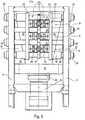
- the device has an L-shaped frame 2.
- the device shown is designed as a multiple punching device for pipes.
- the punching tools are held in a holder 5 which is arranged at the upper end of the vertical leg of the frame. It spans the free space of the L-shape and protrudes slightly towards the front of the horizontal L-leg.
- a lifting table 6 is arranged below the holder 5 and has three receptacles 7 for workpieces 8 arranged in a line one behind the other.
- the workpieces consist of three sections of a cylinder tube of equal length. They are kept strictly vertical in the recordings 7. The details of the lifting table and the recordings will be discussed later.
- the lifting table can be moved up and down along two vertical guides 9, which extend parallel to the L-leg of the frame and are arranged on the frame at a constant mutual distance from one another.
- the punching tools 3 are arranged in pairs in the device. This can be seen particularly clearly from FIG. 3. Three processing stations 10, 11, 12 can be seen, each of which is equipped with two punching tools 3 lying opposite one another.
- Each processing station is able to provide a workpiece, in the present case a cylindrical tube section 8 with a predetermined hole pattern, the hole patterns of the different workpieces not having to be identical to one another.
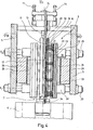
- a mandrel 13 In the core of each processing station, a mandrel 13 is arranged, which protrudes upwards from each station and is supported there by means of adjusting devices 14 so that it can be raised and lowered on a cross member of the holder 5.
- the mandrel has a circular cross section. Along the mandrel axis there is a central bore 15 which runs over the entire height of the mandrel and through which the punching waste falls downward, as will be explained below.
- the vertically aligned mandrel 13 On its outside, the vertically aligned mandrel 13 has a sawtooth profile that has teeth that taper slightly downward. In the area of the teeth, the mandrel is provided with a slot 17 on the circumferential parts opposite the punching tools 3, in order to allow punches 16 of these tools or punching waste to penetrate the mandrel.
- the mandrel forms a central actuating element for two supporting elements 18 arranged next to it, which flank it on opposite sides.
- the support elements are designed as vertical strips and have an approximately rectangular cross section.
- One side of the rectangle is designed as a semicircle and adapted to the inner wall of the workpiece to be machined.
- the support elements 18 can be embedded in vertical grooves of the mandrel. On their side of the rectangle facing the center of the mandrel, they have a sawtooth-like inner surface which corresponds to the sawtooth-like outer surface of the mandrel in such a way that the saw teeth of these two parts hook into one another. This means that the saw teeth of the support elements taper slightly upwards.
- the support elements 18 serve as counterholders for the punching tools 3. If the mandrel is moved vertically downward, the saw teeth of the mandrel run against those of the support elements and press the support elements radially outward into contact with the pipe workpieces. In the device shown, the contact is made at least along the surface lines of the tube workpieces, into which holes are to be punched in accordance with a predetermined pattern.
- the support elements 18 are diametrically opposite with respect to the tube cross section of the workpieces. They are each designed as a matrix containing a hole pattern.
- the grid of holes contains a series of bores located one above the other, which are arranged at a predetermined distance from one another.
- the support elements are used to support the inside of the pipe, the outside are used for fixing Workpieces each have a pair of guide half-shells 19 which have a U-shaped cross section, the opening of which is directed towards the workpiece.
- the U-shape is matched to the diameter and cross-sectional shape of the largest workpiece. It encompasses such a workpiece.
- the guide half-shells 19 can only rest on the workpieces along the surface line which is also provided with the row of holes.
- the guide half-shells have horizontal guide bores for receiving the punches 16 of the punching tools 3. Analogous to the hole pattern of the support elements, the guide bores are arranged vertically one above the other along a line and have the same mutual spacing as is present in the row of holes of the support elements.
- the support elements 18 each have at their upper ends radially outwardly extending hooks 20 with which they are suspended in corresponding recesses in the guide half-shells. In this way, the support elements are mounted on the guide half-shells in a radially variable manner. This is necessary because there must be sufficient space between the support elements and the guide half-shells for moving the workpieces in and out.
- the punches 19 of the punching tools 3 are arranged vertically one above the other, analogous to the bores of the support elements and the guide half-shells. They are aligned horizontally.
- the stamps of each punch 3 extend radially outward from the corresponding guide half-shell to a common actuating element 21 which is formed as a vertical pressure bar.
- the actuating element contains a selective one set of stamps each have a vertical activation bar 22 which connects predetermined stamps to the actuating element in a tensile and compressive manner.
- the activation bars can be inserted from above into a groove in the actuating element and contain stamps that are not used for special processing
- FIG. 3 It can be seen from FIG. 3 that behind the actuating elements 21 arranged on each side of the axis of symmetry S of the machine frame there is a pressure plate 23 which extends over the entire height of the punching tools and in the horizontal direction over the ends of the three processing stations 10, 11, 12 protrudes.
- the pressure plate 23 therefore spans three punching tools 3 of the processing stations 10, 11, 12 located next to one another. This is done deliberately because one wants to achieve a uniform loading of the punching tools during feed.
- a sliding wedge 25 which has a vertical wedge surface that is inclined so that the wedge tapers in the direction of the drive 24, is fastened to the outside of each pressure plate as the first intermediate member.
- Opposite wedges are assigned to the sliding wedges as a second intermediate link, the inclined surface of which is in contact with the inclined surface
- the counter wedges 26 are thus supported with the inclined surface on the sliding wedges, while they are in contact with the mounting plates 5 with the flat wedge surface.
- the counter wedges are fastened at their thickened end to a common yoke 27 which is connected to the central drive 24 in a pull-resistant and thrust-resistant manner via a stroke adjustment element 27.
- the stroke setting element is designed, for example, as a screw connection between the yoke and the punch of the feed drive and is used primarily to shift the stroke as a function of the workpieces to be machined.
- tie rods 29 are connected to one another via, in the present case a total of eight, tie rods 29.
- tie rods are located in a lower plane E1, which, as shown in FIG. 4, extends horizontally in the region of the lower ends of the punching tools 3.
- tie rods are located in a plane E2, which is arranged analogously in the area of the upper end of the punching tools 3.
- the sliding wedges 25 and the counter wedges 26 are arranged between the planes E1 and E2.
- the tie rods are columnar.
- the mounting plates 5 are anchored to pull and slide.
- the columns serve for the storage of several parts, for example the pressure plates 23, which are displaceably supported by means of bushes 30 on the outermost columns of the upper and lower levels E1 and E2.
- spacer blocks 31 are also held on the columns symmetrically to the plane of symmetry S, which in the present case are designed in the form of strips and on twists in the tie rods 29 (see partial section in FIG. 3 above) are fixed immovably in said plane of symmetry.
- the spacer blocks serve as stroke limiters for the guide half-shells 19.
- the half-shells are connected to the actuating elements 21 via horizontal support rods 32. But the connection is not rigid.
- the actuating elements can be moved for the actual punching stroke in the direction of the guide half-shells against the force of springs 33 which are clamped between the guide half-shells 19 on the one hand and the actuating elements 21 on the other hand.
- the spacer blocks 31 project into the stroke area of the guide half-shell 19 and determine the position of the guide half-shells closest to the workpiece as a function of the workpiece during machining. In this way, deformation of the workpieces during punching is to be avoided.
- the guide half-shells 19, the actuating elements 21 and the sliding wedges 25 are thus held in the horizontal direction on the tie rods 29 via the pressure plates 23.
- FIGS. 1 and 2 it is shown in its lower ready position, in which the workpieces can be inserted into the receptacles 7 and removed from them again.
- the lifting table 6 is in the processing position. It has moved all the way to the lower end of the punching tools and has inserted the tubular workpiece 8 so far between the support elements 20 and the guide half-shells 19 that the workpiece can be provided with the desired holes over its entire length.
- the receptacles 7 each have a centering opening 34, into which the mandrel projects when the lifting table is in the processing position. It is held there against lateral displacement.
- the receptacles have an opening which is coaxial with the through hole 15 and through which the punching waste falls downward.
- FIG. 5 schematically shows the rotary drive for the receptacles 7 of the lifting table 6.
- the three receptacles are each rotatably mounted about vertical axes and are connected to one another in motion by means of meshing gears 35, 36 and 37.
- the middle receptacle is connected via a reduction gear 38 to a stepper motor, which is used to gradually turn the workpieces for punching. Since only the bores of a surface line of the workpiece are punched out in each machining operation, the stepwise rotation of the receptacles can result in the entire surface of the workpiece being machined.
- a sheet metal strip or a sheet metal of some kind is first used Cutting pipes shaped and then welded together at the pipe seam. They can then be cut to length.
- a support element is inserted into the already welded pipe and pressed against the pipe. The punching takes place from the outside, the support element serving as a counter-holder for securing the workpiece and for absorbing the punching forces.
- the tube is held vertically during the punching. If a force balance is desired, it is possible to punch the tube simultaneously from two opposite directions.
- the workpieces for example the prefabricated pipes, regardless of whether with a seam or seamlessly, are inserted from above into the receptacles 7 of the lifting table 6 and clamped vertically there.
- the lifting table is in the lower standby position shown in FIGS. 1 and 2. After clamping, the lifting table is moved vertically upwards, whereupon the workpieces are moved into the space between the support elements 20 and 19 as far up as is necessary for the desired machining.
- the mandrel 13 is centered in a centering opening in the receptacles 7.
- the mandrel 13 is displaced downwards for tensioning the support elements 20 with the aid of the actuators 14, whereupon the support elements are pressed radially outward into contact with the workpieces due to the run-up of the saw teeth.
- the actuating elements 21 are advanced in the direction of the workpieces 8.
- the guide half-shells 19 move in the direction of the pipe to be punched and clamp it firmly on the support elements 20. At the same time, they come into contact with the spacer blocks 31, which serve as stroke limiters for the guide half-shells.
- the distance between the actuating elements 21 and the guide half-shells 29 is reduced.
- the springs in between are compressed. They are prestressed so far that they can absorb any unevenly occurring side forces and relieve the mandrel.
- the punches provided for machining the workpiece are connected to the respective actuating element 21 in a tensile and shear-proof manner via the activation bar 22. Only they are pushed forward towards the workpiece and punch the desired holes out of the workpiece.
- the stroke of the punching tools is dimensioned such that the punches penetrate into the mandrel and deliver the punching waste to the vertical through hole 15. The waste falls down through the receptacle 7 into the open.
- each workpiece can be moved a certain step be rotated further, whereupon the previously described punching process takes place again.
- the punch of the central feed drive 24 moves back together with the yoke 27 and the counter wedges 30.
- the springs 33 supported on the guide half-shells fixed by the spacer blocks 31, are able to push back the actuating elements 21 and partially withdraw the punches from the workpieces, while the return stroke is generally carried out by the wedge drive.
- the lifting table moves downward from the processing position shown in FIG. It releases the mandrel 13 at the same time.
- the recordings detach from the workpieces, whereupon these can be removed.
- the device according to the invention offers the manufacturer and customer the possibility of a short disposition. A quick tool change is possible even with different hole diameters. Different hole patterns can be achieved at any time by exchanging the activation bars 22.
- the device is relatively small and requires relatively little investment, which means that even small quantities can be produced economically.
- a decisive advantage of the invention is that the workpieces can be provided with holes over their entire circumference. Both longitudinally welded and seamless drawn tubes can be processed in various materials, especially aluminum.
Landscapes
- Engineering & Computer Science (AREA)
- Mechanical Engineering (AREA)
- Punching Or Piercing (AREA)
- Mechanical Treatment Of Semiconductor (AREA)
- Electrical Discharge Machining, Electrochemical Machining, And Combined Machining (AREA)
- Butt Welding And Welding Of Specific Article (AREA)
- Laser Beam Processing (AREA)
Priority Applications (1)
| Application Number | Priority Date | Filing Date | Title |
|---|---|---|---|
| AT84104663T ATE31883T1 (de) | 1983-05-11 | 1984-04-25 | Vorrichtung zum herstellen von in der mantelflaeche gelochten rohren. |
Applications Claiming Priority (2)
| Application Number | Priority Date | Filing Date | Title |
|---|---|---|---|
| DE3317313A DE3317313C1 (de) | 1983-05-11 | 1983-05-11 | Verfahren und Vorrichtung zum Herstellen von in der Mantelflaeche gelochten Rohren |
| DE3317313 | 1983-05-11 |
Publications (3)
| Publication Number | Publication Date |
|---|---|
| EP0125540A2 true EP0125540A2 (fr) | 1984-11-21 |
| EP0125540A3 EP0125540A3 (en) | 1986-01-02 |
| EP0125540B1 EP0125540B1 (fr) | 1988-01-13 |
Family
ID=6198800
Family Applications (1)
| Application Number | Title | Priority Date | Filing Date |
|---|---|---|---|
| EP19840104663 Expired EP0125540B1 (fr) | 1983-05-11 | 1984-04-25 | Dispositif de fabrication de tubes pourvus de trous dans leur paroi |
Country Status (6)
| Country | Link |
|---|---|
| US (1) | US4616540A (fr) |
| EP (1) | EP0125540B1 (fr) |
| JP (1) | JPS59212130A (fr) |
| AT (1) | ATE31883T1 (fr) |
| CA (1) | CA1243826A (fr) |
| DE (2) | DE3317313C1 (fr) |
Families Citing this family (6)
| Publication number | Priority date | Publication date | Assignee | Title |
|---|---|---|---|---|
| US6378218B2 (en) * | 1995-11-16 | 2002-04-30 | Ulrich Sigwart | Methods and apparatus for making a drug infusion device |
| EP1818581B1 (fr) * | 2006-02-10 | 2014-08-13 | Carl Freudenberg KG | Méthode de fabrication pour un anneau d'étanchéité |
| US20080060199A1 (en) * | 2006-07-25 | 2008-03-13 | Christopher Alfred Fuller | Method of manufacturing a manifold |
| DE502007002627D1 (de) * | 2007-08-01 | 2010-03-04 | Freudenberg Carl Kg | Verfahren zur Herstellung eines Dichtrings |
| US10888912B2 (en) | 2017-07-07 | 2021-01-12 | Inno-Spin LLC | Slew-actuated piercing of radial wall |
| CN113020814B (zh) * | 2021-03-17 | 2023-04-14 | 江西晖旭实业有限公司 | 一种激光切割设备及其批量加工管材的控制方法 |
Family Cites Families (14)
| Publication number | Priority date | Publication date | Assignee | Title |
|---|---|---|---|---|
| US1510718A (en) * | 1922-09-07 | 1924-10-07 | Timken Roller Bearing Co | Press |
| US2630862A (en) * | 1951-09-05 | 1953-03-10 | Musser C Walton | Apparatus for perforating hollow cylindrical objects |
| US3259003A (en) * | 1964-06-26 | 1966-07-05 | American Radiator & Standard | Method and apparatus for forming openings in tubular members |
| US3538735A (en) * | 1967-04-27 | 1970-11-10 | Nathan Dolberg | Multiple side punching machine |
| US3678718A (en) * | 1970-12-04 | 1972-07-25 | William A Brown | Pipe perforating machine |
| US3698274A (en) * | 1971-05-14 | 1972-10-17 | Vogel Tool And Die Corp | Apparatus for piercing openings in tubing |
| DE2231517A1 (de) * | 1972-06-28 | 1974-01-10 | Johannes Heinrich Paffhausen | Stanzvorrichtung zum lochen der wand von rohren |
| DE2632713A1 (de) * | 1976-07-21 | 1978-01-26 | Heinz Spieker | Vorrichtung zum stanzen von loechern in hohlprofile |
| DE2644130A1 (de) * | 1976-09-30 | 1978-04-06 | Osterloh Fa Fritz | Lochwerkzeug zum lochen von praezisionsrohren aus stahl |
| FR2369029A1 (fr) * | 1976-10-29 | 1978-05-26 | Tubes Cie Indle Cale | Unite de poinconnage pour tubes de sections quelconques |
| FR2371979A1 (en) * | 1976-11-29 | 1978-06-23 | Spoorwegmaterieel Metaalconstr | Multi-punch machine tool - has lower matrix with bored holes and upper matrix with punching rods |
| JPS54162289A (en) * | 1978-06-13 | 1979-12-22 | Miyadera Seiki Kk | Drilling device with press |
| JPS55154620U (fr) * | 1979-04-24 | 1980-11-07 | ||
| JPS6021013B2 (ja) * | 1981-06-16 | 1985-05-24 | トヨタ自動車株式会社 | 穴明け加工機 |
-
1983
- 1983-05-11 DE DE3317313A patent/DE3317313C1/de not_active Expired
-
1984
- 1984-04-25 EP EP19840104663 patent/EP0125540B1/fr not_active Expired
- 1984-04-25 DE DE8484104663T patent/DE3468633D1/de not_active Expired
- 1984-04-25 AT AT84104663T patent/ATE31883T1/de not_active IP Right Cessation
- 1984-05-08 CA CA000453770A patent/CA1243826A/fr not_active Expired
- 1984-05-09 US US06/608,596 patent/US4616540A/en not_active Expired - Lifetime
- 1984-05-10 JP JP59093810A patent/JPS59212130A/ja active Granted
Also Published As
| Publication number | Publication date |
|---|---|
| ATE31883T1 (de) | 1988-01-15 |
| DE3317313C1 (de) | 1984-08-30 |
| JPH051092B2 (fr) | 1993-01-07 |
| DE3468633D1 (en) | 1988-02-18 |
| EP0125540B1 (fr) | 1988-01-13 |
| EP0125540A3 (en) | 1986-01-02 |
| JPS59212130A (ja) | 1984-12-01 |
| US4616540A (en) | 1986-10-14 |
| CA1243826A (fr) | 1988-11-01 |
Similar Documents
| Publication | Publication Date | Title |
|---|---|---|
| DE2839978C2 (fr) | ||
| EP0178640B1 (fr) | Poinçonneuse et procédé de mise en oeuvre de cette poinçonneuse | |
| EP0454619B1 (fr) | Machine de cintrage d'une tôle en forme de cylindre | |
| EP2233221A2 (fr) | Dispositif de poinçonnage pour une machine de poinçonnage à coupe continue d'éléments de poinçonnage métalliques | |
| DE3915555C2 (de) | Blechbiegemaschine | |
| DE10013690A1 (de) | Verfahren zur Herstellung von aus Blechteilen bestehenden Paketen | |
| DE2741576A1 (de) | Bearbeitungsmaschine fuer draht und band, insbesondere stanz- und biegeautomat, mit mehreren werkzeugebenen | |
| EP3515624A1 (fr) | Procédé, machine-outil et outil de découpage pour le découpage continu à course multiple de pièces en forme de plaque | |
| DE2441965A1 (de) | Anordnung zum bedienen insbesondere einer einseitig offenen presse | |
| DE2002015C3 (de) | Vorrichtung zum Längsschweißen von rohrförmigen Werkstücken | |
| EP0641265B1 (fr) | Machine a dresser | |
| DE3317313C1 (de) | Verfahren und Vorrichtung zum Herstellen von in der Mantelflaeche gelochten Rohren | |
| DE2221194C3 (de) | Vorrichtung zum schrittweisen Vorschieben von Flachmaterial zu einer Abschneideeinrichtung für wärmespeichernde Elemente für Wärmetauscher | |
| DE2943960A1 (de) | Verfahren zur ausbildung von rohrbogen und einrichtung zur durchfuehrung des verfahrens | |
| DE2843531C2 (de) | Maschine zum Herstellen von gitterträgerartigen Bewehrungsgebilden für Stahlbeton | |
| DE2827046A1 (de) | Vorrichtung fuer den werkzeugwechsel in einer stanzmaschine, insbesondere einer revolverpresse | |
| DE3149621A1 (de) | Stanzvorrichtung | |
| EP0368967B1 (fr) | Procede et dispositif pour la fabrication de corps de treillis soudes a deux couches | |
| CH674165A5 (fr) | ||
| DE2226555C3 (de) | Stanznietmaschine zum Eintreiben eines Drahtabschnittes durch ungelochte Werkstücke | |
| DE19611611A1 (de) | Presse | |
| CH689689A5 (de) | Verfahren zur programmgesteuerten Dünnblech-Bearbeitung sowie Dünnblech-Bearbeitungsmaschine. | |
| DE2721610B1 (de) | Presse zum Vorbiegen von Blechzuschnitten bei der Herstellung von Grossrohren | |
| DE2754686C3 (de) | Einrichtung zum Richten von Flanschspulen | |
| DE2742026C3 (de) | Rohrformmaschine |
Legal Events
| Date | Code | Title | Description |
|---|---|---|---|
| PUAI | Public reference made under article 153(3) epc to a published international application that has entered the european phase |
Free format text: ORIGINAL CODE: 0009012 |
|
| AK | Designated contracting states |
Designated state(s): AT BE DE FR GB IT NL SE |
|
| EL | Fr: translation of claims filed | ||
| ITCL | It: translation for ep claims filed |
Representative=s name: JACOBACCI CASETTA & PERANI S.P.A. |
|
| PUAL | Search report despatched |
Free format text: ORIGINAL CODE: 0009013 |
|
| AK | Designated contracting states |
Designated state(s): AT BE DE FR GB IT NL SE |
|
| 17P | Request for examination filed |
Effective date: 19851113 |
|
| 17Q | First examination report despatched |
Effective date: 19860708 |
|
| GRAA | (expected) grant |
Free format text: ORIGINAL CODE: 0009210 |
|
| AK | Designated contracting states |
Kind code of ref document: B1 Designated state(s): AT BE DE FR GB IT NL SE |
|
| REF | Corresponds to: |
Ref document number: 31883 Country of ref document: AT Date of ref document: 19880115 Kind code of ref document: T |
|
| ITF | It: translation for a ep patent filed | ||
| GBT | Gb: translation of ep patent filed (gb section 77(6)(a)/1977) | ||
| REF | Corresponds to: |
Ref document number: 3468633 Country of ref document: DE Date of ref document: 19880218 |
|
| ET | Fr: translation filed | ||
| PLBE | No opposition filed within time limit |
Free format text: ORIGINAL CODE: 0009261 |
|
| STAA | Information on the status of an ep patent application or granted ep patent |
Free format text: STATUS: NO OPPOSITION FILED WITHIN TIME LIMIT |
|
| 26N | No opposition filed | ||
| ITTA | It: last paid annual fee | ||
| EAL | Se: european patent in force in sweden |
Ref document number: 84104663.4 |
|
| REG | Reference to a national code |
Ref country code: GB Ref legal event code: IF02 |
|
| PGFP | Annual fee paid to national office [announced via postgrant information from national office to epo] |
Ref country code: GB Payment date: 20020328 Year of fee payment: 19 |
|
| PGFP | Annual fee paid to national office [announced via postgrant information from national office to epo] |
Ref country code: SE Payment date: 20020423 Year of fee payment: 19 Ref country code: FR Payment date: 20020423 Year of fee payment: 19 |
|
| PGFP | Annual fee paid to national office [announced via postgrant information from national office to epo] |
Ref country code: NL Payment date: 20020425 Year of fee payment: 19 Ref country code: AT Payment date: 20020425 Year of fee payment: 19 |
|
| PGFP | Annual fee paid to national office [announced via postgrant information from national office to epo] |
Ref country code: BE Payment date: 20020429 Year of fee payment: 19 |
|
| PGFP | Annual fee paid to national office [announced via postgrant information from national office to epo] |
Ref country code: DE Payment date: 20020531 Year of fee payment: 19 |
|
| PG25 | Lapsed in a contracting state [announced via postgrant information from national office to epo] |
Ref country code: GB Free format text: LAPSE BECAUSE OF NON-PAYMENT OF DUE FEES Effective date: 20030425 Ref country code: AT Free format text: LAPSE BECAUSE OF NON-PAYMENT OF DUE FEES Effective date: 20030425 |
|
| PG25 | Lapsed in a contracting state [announced via postgrant information from national office to epo] |
Ref country code: SE Free format text: LAPSE BECAUSE OF NON-PAYMENT OF DUE FEES Effective date: 20030426 |
|
| PG25 | Lapsed in a contracting state [announced via postgrant information from national office to epo] |
Ref country code: BE Free format text: LAPSE BECAUSE OF NON-PAYMENT OF DUE FEES Effective date: 20030430 |
|
| BERE | Be: lapsed |
Owner name: *MORHARD ALFRED Effective date: 20030430 |
|
| PG25 | Lapsed in a contracting state [announced via postgrant information from national office to epo] |
Ref country code: NL Free format text: LAPSE BECAUSE OF NON-PAYMENT OF DUE FEES Effective date: 20031101 Ref country code: DE Free format text: LAPSE BECAUSE OF NON-PAYMENT OF DUE FEES Effective date: 20031101 |
|
| NLV4 | Nl: lapsed or anulled due to non-payment of the annual fee |
Effective date: 20031101 |
|
| EUG | Se: european patent has lapsed | ||
| GBPC | Gb: european patent ceased through non-payment of renewal fee | ||
| PG25 | Lapsed in a contracting state [announced via postgrant information from national office to epo] |
Ref country code: FR Free format text: LAPSE BECAUSE OF NON-PAYMENT OF DUE FEES Effective date: 20031231 |
|
| REG | Reference to a national code |
Ref country code: FR Ref legal event code: ST |