EP0125578A1 - Bracelet, en particulier bracelet de montre - Google Patents
Bracelet, en particulier bracelet de montre Download PDFInfo
- Publication number
- EP0125578A1 EP0125578A1 EP84105037A EP84105037A EP0125578A1 EP 0125578 A1 EP0125578 A1 EP 0125578A1 EP 84105037 A EP84105037 A EP 84105037A EP 84105037 A EP84105037 A EP 84105037A EP 0125578 A1 EP0125578 A1 EP 0125578A1
- Authority
- EP
- European Patent Office
- Prior art keywords
- joint
- locking ball
- link
- band
- incision
- Prior art date
- Legal status (The legal status is an assumption and is not a legal conclusion. Google has not performed a legal analysis and makes no representation as to the accuracy of the status listed.)
- Granted
Links
- 210000000707 wrist Anatomy 0.000 title description 2
- 238000006073 displacement reaction Methods 0.000 claims abstract description 15
- 238000000034 method Methods 0.000 claims description 2
- 230000002265 prevention Effects 0.000 claims 1
- 230000013011 mating Effects 0.000 abstract 3
- 241001295925 Gegenes Species 0.000 description 2
- 230000000903 blocking effect Effects 0.000 description 2
- 238000004519 manufacturing process Methods 0.000 description 2
- 239000000463 material Substances 0.000 description 2
- 101100008050 Caenorhabditis elegans cut-6 gene Proteins 0.000 description 1
- 238000010276 construction Methods 0.000 description 1
- 238000003780 insertion Methods 0.000 description 1
- 230000037431 insertion Effects 0.000 description 1
- 239000002184 metal Substances 0.000 description 1
- 238000000926 separation method Methods 0.000 description 1
Images

Classifications
-
- A—HUMAN NECESSITIES
- A44—HABERDASHERY; JEWELLERY
- A44C—PERSONAL ADORNMENTS, e.g. JEWELLERY; COINS
- A44C5/00—Bracelets; Wrist-watch straps; Fastenings for bracelets or wrist-watch straps
- A44C5/02—Link constructions
- A44C5/10—Link constructions not extensible
- A44C5/105—Link constructions not extensible with links made of one piece and linked together by one connecting element
Definitions
- the object of the invention is to prevent the mutual displacement in the longitudinal direction of the articulated groove in a bracelet, in particular a watch strap of this type, and consequently the removal of the hinged band links with means that are simple in terms of construction, easy to manufacture and cost-effective to produce.
- this object is achieved in that, in order to prevent the mutual displacement of two band links which are connected to one another in an articulated manner, at least one locking ball is introduced into an approximately perpendicular to the bracelet surface in which a band link is provided in the area of the articulated groove and overlaps this receiving bore with frictional engagement and in engages an associated incision provided in the joint approach of the other band link.
- a simple locking ball is used to prevent the mutual displacement of the wrist-linked bracelet links in the longitudinal direction of the joint groove, which is cheaply available in any, even very small dimensions and from any material as a commercially available product.
- this ball is only necessary in each band link in the area of the articulated groove to have an overlapping hole that is perpendicular to the area of the bracelet and aligned with this hole in Joint approach to create a simple incision, which can be achieved easily and quickly with relatively little effort and cost.
- the locking ball is easy to handle when inserted into the associated mounting hole and does not require any special tools or working methods.
- the mounting hole for the locking ball can overlap the joint groove of the bracelet link by any proportion of the hole diameter or the joint groove depth.
- the receiving bore for the locking ball is preferably designed as a blind bore. This prevents dirt from entering this hole, since its only open mouth is closed by the inserted locking ball.
- the blind holes for receiving the locking balls are only visible on one side of the band links, so that it is possible to select them on the outer visible side of the bracelet, e.g. to be arranged as decorative elements or on the inner side of the band, which is invisible when the bracelet is worn.
- the frictional connection between the locking ball and the wall of the receiving bore can be achieved in that the diameter of the receiving bore by a small amount, corresponding to the material of the band links and the locking balls, e.g. is about 0.05 mm smaller than the diameter of the locking ball. So e.g. In the case of metallic bracelet links and locking balls, the diameter of the locking balls can be approximately 1.0 mm and the diameter of the locating holes can be approximately 0.95 mm.
- an incision is particularly advantageous which, in plan view, has an approximately rectangular shape with side walls approximately parallel to one another, because such an incision is particularly easy to produce and, at the same time, prevents the mutually articulated bracelet links from being displaced with the greatest possible security.
- the band links can be detached from one another simply and quickly only by a stronger mutual displacement across the bracelet without special tools. It is therefore possible to link individual band links e.g. to shorten the bracelet without difficulty.
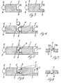
- the bracelet shown is intended in particular for use as a watch strap and consists of adjacently arranged, articulated links 1.
- each band link On its side opposite the joint set 2, each band link has a joint groove 3, which likewise preferably extends over the entire corresponding side of the band link 1 and has a circular segment-shaped cross section adapted to the joint extension 2.
- Two band links 1 lying next to each other are connected to one another in a form-fitting, articulated manner in that the joint extension 2 of one band link is pushed in its longitudinal direction into the joint groove 3 of the other band link.
- each band link 1 is preferably made of metal and each band link has a slightly bevelled surface 4 on at least one side of its joint attachment 2 on the head side, which means that the two hinged bands are pivoted to a limited extent links 1 in the direction of the restriction 4, as shown in dash-dotted lines in Fig. 6.
- each band link 1 can also have such a bevel 4 on both sides of its joint attachment 2.
- Each band link 1 has in one of its wide areas in the center in the region of its articulated groove 3 a blind bore 5 directed perpendicularly to the plane of the band link, which bores the articulated groove 3 e.g. about half of the bore diameter and / or the joint groove depth.
- an incision 6 is provided in the joint attachment 2 of each band link 1, which has an approximately rectangular shape in plan view with parallel side walls.
- the blind bores 5 are designed as receiving bores for one metallic locking ball 7 each, which has a larger diameter than the diameter of the bore 5 such that it can be inserted into this bore 5 with frictional engagement and held therein.
- the locking ball 7 can e.g. have a diameter of about 1.0 mm.
- the diameter of the receiving bore can then be approximately 0.95 mm.
- the locking ball 7 is inserted into the receiving bore 5 of one band link and pressed so deep into this bore 5 that it is in the associated, in the joint approach 2 of the other, articulated bracelet link 1 provided incision 6 engages, as shown in particular in FIGS. 5 and 6.
- the blocking ball 7 prevents the mutual displacement and, consequently, the unintentional separation of the two band bands 1 which are articulated to one another.
- the receiving bore 5 for the locking ball 7 has such a depth that the locking ball 7 can optionally occupy two different positions therein.
- the links 1 of the bracelet or watch band are each arranged with a single, central one in the region of the articulated groove 3 Receiving hole 5 for a locking ball 7 and each with an aligned cut 6 in the joint approach 2.
- each band link 1 two or more receiving holes 5 distributed in the longitudinal direction of the articulated groove 3, each of which overlaps one locking ball 7 and two or more incisions 6 in the articulated attachment 2, each with one receiving hole 5.
Landscapes
- Buckles (AREA)
- Physical Vapour Deposition (AREA)
- Purses, Travelling Bags, Baskets, Or Suitcases (AREA)
- Professional, Industrial, Or Sporting Protective Garments (AREA)
Priority Applications (1)
| Application Number | Priority Date | Filing Date | Title |
|---|---|---|---|
| AT84105037T ATE28120T1 (de) | 1983-05-11 | 1984-05-04 | Armband, insbesondere uhrarmband. |
Applications Claiming Priority (2)
| Application Number | Priority Date | Filing Date | Title |
|---|---|---|---|
| IT12516/83A IT1171154B (it) | 1983-05-11 | 1983-05-11 | Elemento metallico per formare cin turini da orologi da polso a maglie snodate smembrabili e non |
| IT1251683 | 1983-05-11 |
Publications (2)
| Publication Number | Publication Date |
|---|---|
| EP0125578A1 true EP0125578A1 (fr) | 1984-11-21 |
| EP0125578B1 EP0125578B1 (fr) | 1987-07-08 |
Family
ID=11141084
Family Applications (1)
| Application Number | Title | Priority Date | Filing Date |
|---|---|---|---|
| EP84105037A Expired EP0125578B1 (fr) | 1983-05-11 | 1984-05-04 | Bracelet, en particulier bracelet de montre |
Country Status (4)
| Country | Link |
|---|---|
| EP (1) | EP0125578B1 (fr) |
| AT (1) | ATE28120T1 (fr) |
| DE (1) | DE3464536D1 (fr) |
| IT (1) | IT1171154B (fr) |
Cited By (3)
| Publication number | Priority date | Publication date | Assignee | Title |
|---|---|---|---|---|
| FR2723823A1 (fr) * | 1994-08-30 | 1996-03-01 | Techni Concept International | Bracelet souple a maillons articules |
| WO1998008408A1 (fr) * | 1996-08-29 | 1998-03-05 | Tag Heuer S.A. | Bracelet a maillons articules et montre munie d'un tel bracelet |
| CN111053338A (zh) * | 2019-12-31 | 2020-04-24 | 歌尔科技有限公司 | 表带及可穿戴设备 |
Citations (6)
| Publication number | Priority date | Publication date | Assignee | Title |
|---|---|---|---|---|
| CH463847A (de) * | 1965-08-11 | 1968-10-15 | Okamura Yuji | Armband, insbesondere für Armbanduhren |
| CH483212A (fr) * | 1967-01-03 | 1969-12-31 | Moblot Manufacture Rene Martha | Bracelet, notamment pour montre |
| DE1557632A1 (de) * | 1967-07-26 | 1970-04-02 | Rodi & Wienerberger Ag | Metallarmband |
| CH573731A5 (en) * | 1975-05-05 | 1976-03-31 | Dubois Bernard | Non expanding metallic watch bracelet - has pivotally connected links with spring loaded locking pins |
| CH614360A5 (en) * | 1977-08-25 | 1979-11-30 | Bear & Cie Sa | Method for manufacturing a bracelet and bracelet obtained by this method |
| EP0089421A1 (fr) * | 1982-03-24 | 1983-09-28 | BEAR & CIE S.A. | Bracelet, notamment pour montre et procédé de montage d'un tel bracelet |
-
1983
- 1983-05-11 IT IT12516/83A patent/IT1171154B/it active
-
1984
- 1984-05-04 EP EP84105037A patent/EP0125578B1/fr not_active Expired
- 1984-05-04 DE DE8484105037T patent/DE3464536D1/de not_active Expired
- 1984-05-04 AT AT84105037T patent/ATE28120T1/de not_active IP Right Cessation
Patent Citations (6)
| Publication number | Priority date | Publication date | Assignee | Title |
|---|---|---|---|---|
| CH463847A (de) * | 1965-08-11 | 1968-10-15 | Okamura Yuji | Armband, insbesondere für Armbanduhren |
| CH483212A (fr) * | 1967-01-03 | 1969-12-31 | Moblot Manufacture Rene Martha | Bracelet, notamment pour montre |
| DE1557632A1 (de) * | 1967-07-26 | 1970-04-02 | Rodi & Wienerberger Ag | Metallarmband |
| CH573731A5 (en) * | 1975-05-05 | 1976-03-31 | Dubois Bernard | Non expanding metallic watch bracelet - has pivotally connected links with spring loaded locking pins |
| CH614360A5 (en) * | 1977-08-25 | 1979-11-30 | Bear & Cie Sa | Method for manufacturing a bracelet and bracelet obtained by this method |
| EP0089421A1 (fr) * | 1982-03-24 | 1983-09-28 | BEAR & CIE S.A. | Bracelet, notamment pour montre et procédé de montage d'un tel bracelet |
Cited By (5)
| Publication number | Priority date | Publication date | Assignee | Title |
|---|---|---|---|---|
| FR2723823A1 (fr) * | 1994-08-30 | 1996-03-01 | Techni Concept International | Bracelet souple a maillons articules |
| WO1996006542A1 (fr) * | 1994-08-30 | 1996-03-07 | Techni-Concept International | Bracelet souple a maillons articules |
| WO1998008408A1 (fr) * | 1996-08-29 | 1998-03-05 | Tag Heuer S.A. | Bracelet a maillons articules et montre munie d'un tel bracelet |
| US6079196A (en) * | 1996-08-29 | 2000-06-27 | Tag Heuer Sa | Band of articulated links and watch provided with such a band |
| CN111053338A (zh) * | 2019-12-31 | 2020-04-24 | 歌尔科技有限公司 | 表带及可穿戴设备 |
Also Published As
| Publication number | Publication date |
|---|---|
| IT8312516A0 (it) | 1983-05-11 |
| ATE28120T1 (de) | 1987-07-15 |
| EP0125578B1 (fr) | 1987-07-08 |
| IT1171154B (it) | 1987-06-10 |
| DE3464536D1 (en) | 1987-08-13 |
Similar Documents
| Publication | Publication Date | Title |
|---|---|---|
| DE2461766B2 (de) | Kassette zur Aufbewahrung länglicher Gegenstände, insbesondere Werkzeuge | |
| DE602004011530T2 (de) | Vorrichtung zur befestigung eines endes eines bandes auf einem gegenstand | |
| DE10261200A1 (de) | Stumpfschneidevorrichtung | |
| DE69613595T2 (de) | Uhrarmband mit gelenkten gliedern | |
| EP0125578B1 (fr) | Bracelet, en particulier bracelet de montre | |
| DE2114206A1 (de) | Verschleissglied fuer Reifenketten | |
| DE4128512A1 (de) | Knebelsicherung fuer rinnenschuss-knebelverbindungen u. dgl. | |
| DE3837261C2 (fr) | ||
| DE2903824A1 (de) | Vorrichtung zum verbinden von profilschienen | |
| DE3723362A1 (de) | Energiefuehrungskette aus kunststoff | |
| DE60226210T2 (de) | Uhrgehäuse mit armband | |
| DE4035548C2 (de) | Anordnung zum Fixieren von Knochenabschnitten | |
| CH639832A5 (de) | Gliederband in form eines schmuckbandes, armbandes oder guertels. | |
| DE2835410A1 (de) | Schraempicke | |
| DE102021112057B3 (de) | Schließe für Armbänder, Gürtel, Geschmeide und dergleichen | |
| DE4312761C2 (de) | Schmuckstück | |
| LU503506B1 (de) | Einrichtung zur Verbindung zweier Strangenden | |
| EP0444238B1 (fr) | Bracelet-montre avec fermoir | |
| DE3423273C1 (de) | Verbindungsstück für zwei zu verspannende, verdickte Seilenden | |
| EP1495996A2 (fr) | Convoyeur à charnieres avec dispositif de guidage | |
| EP0838174A2 (fr) | Bijou en forme d'anneau | |
| DE3400647C2 (fr) | ||
| EP0486779A2 (fr) | Dispositif de blocage de corde avec au moins une corde traversante et un dispositif d'arrêt de corde | |
| DE1148481B (de) | Saegekette fuer Motorkettensaegen | |
| DE202006016968U1 (de) | Schmuckring |
Legal Events
| Date | Code | Title | Description |
|---|---|---|---|
| PUAI | Public reference made under article 153(3) epc to a published international application that has entered the european phase |
Free format text: ORIGINAL CODE: 0009012 |
|
| AK | Designated contracting states |
Designated state(s): AT BE CH DE FR GB IT LI LU NL SE |
|
| 17P | Request for examination filed |
Effective date: 19850111 |
|
| GRAA | (expected) grant |
Free format text: ORIGINAL CODE: 0009210 |
|
| AK | Designated contracting states |
Kind code of ref document: B1 Designated state(s): AT BE CH DE FR GB IT LI LU NL SE |
|
| PG25 | Lapsed in a contracting state [announced via postgrant information from national office to epo] |
Ref country code: NL Effective date: 19870708 Ref country code: IT Free format text: LAPSE BECAUSE OF FAILURE TO SUBMIT A TRANSLATION OF THE DESCRIPTION OR TO PAY THE FEE WITHIN THE PRESCRIBED TIME-LIMIT;WARNING: LAPSES OF ITALIAN PATENTS WITH EFFECTIVE DATE BEFORE 2007 MAY HAVE OCCURRED AT ANY TIME BEFORE 2007. THE CORRECT EFFECTIVE DATE MAY BE DIFFERENT FROM THE ONE RECORDED. Effective date: 19870708 Ref country code: BE Effective date: 19870708 |
|
| REF | Corresponds to: |
Ref document number: 28120 Country of ref document: AT Date of ref document: 19870715 Kind code of ref document: T |
|
| PG25 | Lapsed in a contracting state [announced via postgrant information from national office to epo] |
Ref country code: SE Effective date: 19870731 |
|
| REF | Corresponds to: |
Ref document number: 3464536 Country of ref document: DE Date of ref document: 19870813 |
|
| ET | Fr: translation filed | ||
| NLV1 | Nl: lapsed or annulled due to failure to fulfill the requirements of art. 29p and 29m of the patents act | ||
| PG25 | Lapsed in a contracting state [announced via postgrant information from national office to epo] |
Ref country code: GB Effective date: 19880504 Ref country code: AT Effective date: 19880504 |
|
| PLBE | No opposition filed within time limit |
Free format text: ORIGINAL CODE: 0009261 |
|
| STAA | Information on the status of an ep patent application or granted ep patent |
Free format text: STATUS: NO OPPOSITION FILED WITHIN TIME LIMIT |
|
| PG25 | Lapsed in a contracting state [announced via postgrant information from national office to epo] |
Ref country code: LU Free format text: LAPSE BECAUSE OF NON-PAYMENT OF DUE FEES Effective date: 19880531 |
|
| 26N | No opposition filed | ||
| GBPC | Gb: european patent ceased through non-payment of renewal fee | ||
| PGFP | Annual fee paid to national office [announced via postgrant information from national office to epo] |
Ref country code: FR Payment date: 19930423 Year of fee payment: 10 |
|
| PGFP | Annual fee paid to national office [announced via postgrant information from national office to epo] |
Ref country code: DE Payment date: 19930427 Year of fee payment: 10 |
|
| PGFP | Annual fee paid to national office [announced via postgrant information from national office to epo] |
Ref country code: CH Payment date: 19930428 Year of fee payment: 10 |
|
| PG25 | Lapsed in a contracting state [announced via postgrant information from national office to epo] |
Ref country code: LI Effective date: 19940531 Ref country code: CH Effective date: 19940531 |
|
| PG25 | Lapsed in a contracting state [announced via postgrant information from national office to epo] |
Ref country code: FR Effective date: 19950131 |
|
| REG | Reference to a national code |
Ref country code: CH Ref legal event code: PL |
|
| PG25 | Lapsed in a contracting state [announced via postgrant information from national office to epo] |
Ref country code: DE Effective date: 19950201 |
|
| REG | Reference to a national code |
Ref country code: FR Ref legal event code: ST |