EP0125584A2 - Appareil de fixation d'une feuille sous forme de film sur une surface de panneau - Google Patents
Appareil de fixation d'une feuille sous forme de film sur une surface de panneau Download PDFInfo
- Publication number
- EP0125584A2 EP0125584A2 EP84105062A EP84105062A EP0125584A2 EP 0125584 A2 EP0125584 A2 EP 0125584A2 EP 84105062 A EP84105062 A EP 84105062A EP 84105062 A EP84105062 A EP 84105062A EP 0125584 A2 EP0125584 A2 EP 0125584A2
- Authority
- EP
- European Patent Office
- Prior art keywords
- panel
- laminator
- film web
- block members
- tacking
- Prior art date
- Legal status (The legal status is an assumption and is not a legal conclusion. Google has not performed a legal analysis and makes no representation as to the accuracy of the status listed.)
- Granted
Links
Images

Classifications
-
- G—PHYSICS
- G06—COMPUTING OR CALCULATING; COUNTING
- G06F—ELECTRIC DIGITAL DATA PROCESSING
- G06F9/00—Arrangements for program control, e.g. control units
- G06F9/06—Arrangements for program control, e.g. control units using stored programs, i.e. using an internal store of processing equipment to receive or retain programs
- G06F9/30—Arrangements for executing machine instructions, e.g. instruction decode
-
- B—PERFORMING OPERATIONS; TRANSPORTING
- B32—LAYERED PRODUCTS
- B32B—LAYERED PRODUCTS, i.e. PRODUCTS BUILT-UP OF STRATA OF FLAT OR NON-FLAT, e.g. CELLULAR OR HONEYCOMB, FORM
- B32B37/00—Methods or apparatus for laminating, e.g. by curing or by ultrasonic bonding
- B32B37/14—Methods or apparatus for laminating, e.g. by curing or by ultrasonic bonding characterised by the properties of the layers
- B32B37/16—Methods or apparatus for laminating, e.g. by curing or by ultrasonic bonding characterised by the properties of the layers with all layers existing as coherent layers before laminating
- B32B37/22—Methods or apparatus for laminating, e.g. by curing or by ultrasonic bonding characterised by the properties of the layers with all layers existing as coherent layers before laminating involving the assembly of both discrete and continuous layers
- B32B37/223—One or more of the layers being plastic
- B32B37/226—Laminating sheets, panels or inserts between two continuous plastic layers
-
- B—PERFORMING OPERATIONS; TRANSPORTING
- B29—WORKING OF PLASTICS; WORKING OF SUBSTANCES IN A PLASTIC STATE IN GENERAL
- B29C—SHAPING OR JOINING OF PLASTICS; SHAPING OF MATERIAL IN A PLASTIC STATE, NOT OTHERWISE PROVIDED FOR; AFTER-TREATMENT OF THE SHAPED PRODUCTS, e.g. REPAIRING
- B29C63/00—Lining or sheathing, i.e. applying preformed layers or sheathings of plastics; Apparatus therefor
- B29C63/02—Lining or sheathing, i.e. applying preformed layers or sheathings of plastics; Apparatus therefor using sheet or web-like material
-
- B—PERFORMING OPERATIONS; TRANSPORTING
- B32—LAYERED PRODUCTS
- B32B—LAYERED PRODUCTS, i.e. PRODUCTS BUILT-UP OF STRATA OF FLAT OR NON-FLAT, e.g. CELLULAR OR HONEYCOMB, FORM
- B32B38/00—Ancillary operations in connection with laminating processes
- B32B38/18—Handling of layers or the laminate
- B32B38/1825—Handling of layers or the laminate characterised by the control or constructional features of devices for tensioning, stretching or registration
- B32B38/1833—Positioning, e.g. registration or centering
- B32B38/1841—Positioning, e.g. registration or centering during laying up
- B32B38/185—Positioning, e.g. registration or centering during laying up combined with the cutting of one or more layers
-
- B—PERFORMING OPERATIONS; TRANSPORTING
- B32—LAYERED PRODUCTS
- B32B—LAYERED PRODUCTS, i.e. PRODUCTS BUILT-UP OF STRATA OF FLAT OR NON-FLAT, e.g. CELLULAR OR HONEYCOMB, FORM
- B32B2457/00—Electrical equipment
- B32B2457/08—PCBs, i.e. printed circuit boards
-
- H—ELECTRICITY
- H05—ELECTRIC TECHNIQUES NOT OTHERWISE PROVIDED FOR
- H05K—PRINTED CIRCUITS; CASINGS OR CONSTRUCTIONAL DETAILS OF ELECTRIC APPARATUS; MANUFACTURE OF ASSEMBLAGES OF ELECTRICAL COMPONENTS
- H05K3/00—Apparatus or processes for manufacturing printed circuits
- H05K3/0073—Masks not provided for in groups H05K3/02 - H05K3/46, e.g. for photomechanical production of patterned surfaces
- H05K3/0079—Masks not provided for in groups H05K3/02 - H05K3/46, e.g. for photomechanical production of patterned surfaces characterised by the method of application or removal of the mask
-
- Y—GENERAL TAGGING OF NEW TECHNOLOGICAL DEVELOPMENTS; GENERAL TAGGING OF CROSS-SECTIONAL TECHNOLOGIES SPANNING OVER SEVERAL SECTIONS OF THE IPC; TECHNICAL SUBJECTS COVERED BY FORMER USPC CROSS-REFERENCE ART COLLECTIONS [XRACs] AND DIGESTS
- Y10—TECHNICAL SUBJECTS COVERED BY FORMER USPC
- Y10T—TECHNICAL SUBJECTS COVERED BY FORMER US CLASSIFICATION
- Y10T156/00—Adhesive bonding and miscellaneous chemical manufacture
- Y10T156/10—Methods of surface bonding and/or assembly therefor
- Y10T156/1052—Methods of surface bonding and/or assembly therefor with cutting, punching, tearing or severing
-
- Y—GENERAL TAGGING OF NEW TECHNOLOGICAL DEVELOPMENTS; GENERAL TAGGING OF CROSS-SECTIONAL TECHNOLOGIES SPANNING OVER SEVERAL SECTIONS OF THE IPC; TECHNICAL SUBJECTS COVERED BY FORMER USPC CROSS-REFERENCE ART COLLECTIONS [XRACs] AND DIGESTS
- Y10—TECHNICAL SUBJECTS COVERED BY FORMER USPC
- Y10T—TECHNICAL SUBJECTS COVERED BY FORMER US CLASSIFICATION
- Y10T156/00—Adhesive bonding and miscellaneous chemical manufacture
- Y10T156/12—Surface bonding means and/or assembly means with cutting, punching, piercing, severing or tearing
-
- Y—GENERAL TAGGING OF NEW TECHNOLOGICAL DEVELOPMENTS; GENERAL TAGGING OF CROSS-SECTIONAL TECHNOLOGIES SPANNING OVER SEVERAL SECTIONS OF THE IPC; TECHNICAL SUBJECTS COVERED BY FORMER USPC CROSS-REFERENCE ART COLLECTIONS [XRACs] AND DIGESTS
- Y10—TECHNICAL SUBJECTS COVERED BY FORMER USPC
- Y10T—TECHNICAL SUBJECTS COVERED BY FORMER US CLASSIFICATION
- Y10T156/00—Adhesive bonding and miscellaneous chemical manufacture
- Y10T156/12—Surface bonding means and/or assembly means with cutting, punching, piercing, severing or tearing
- Y10T156/1317—Means feeding plural workpieces to be joined
- Y10T156/1322—Severing before bonding or assembling of parts
- Y10T156/1339—Delivering cut part in sequence to serially conveyed articles
-
- Y—GENERAL TAGGING OF NEW TECHNOLOGICAL DEVELOPMENTS; GENERAL TAGGING OF CROSS-SECTIONAL TECHNOLOGIES SPANNING OVER SEVERAL SECTIONS OF THE IPC; TECHNICAL SUBJECTS COVERED BY FORMER USPC CROSS-REFERENCE ART COLLECTIONS [XRACs] AND DIGESTS
- Y10—TECHNICAL SUBJECTS COVERED BY FORMER USPC
- Y10T—TECHNICAL SUBJECTS COVERED BY FORMER US CLASSIFICATION
- Y10T156/00—Adhesive bonding and miscellaneous chemical manufacture
- Y10T156/12—Surface bonding means and/or assembly means with cutting, punching, piercing, severing or tearing
- Y10T156/1317—Means feeding plural workpieces to be joined
- Y10T156/1343—Cutting indefinite length web after assembly with discrete article
-
- Y—GENERAL TAGGING OF NEW TECHNOLOGICAL DEVELOPMENTS; GENERAL TAGGING OF CROSS-SECTIONAL TECHNOLOGIES SPANNING OVER SEVERAL SECTIONS OF THE IPC; TECHNICAL SUBJECTS COVERED BY FORMER USPC CROSS-REFERENCE ART COLLECTIONS [XRACs] AND DIGESTS
- Y10—TECHNICAL SUBJECTS COVERED BY FORMER USPC
- Y10T—TECHNICAL SUBJECTS COVERED BY FORMER US CLASSIFICATION
- Y10T156/00—Adhesive bonding and miscellaneous chemical manufacture
- Y10T156/17—Surface bonding means and/or assemblymeans with work feeding or handling means
- Y10T156/1702—For plural parts or plural areas of single part
- Y10T156/1712—Indefinite or running length work
- Y10T156/1734—Means bringing articles into association with web
-
- Y—GENERAL TAGGING OF NEW TECHNOLOGICAL DEVELOPMENTS; GENERAL TAGGING OF CROSS-SECTIONAL TECHNOLOGIES SPANNING OVER SEVERAL SECTIONS OF THE IPC; TECHNICAL SUBJECTS COVERED BY FORMER USPC CROSS-REFERENCE ART COLLECTIONS [XRACs] AND DIGESTS
- Y10—TECHNICAL SUBJECTS COVERED BY FORMER USPC
- Y10T—TECHNICAL SUBJECTS COVERED BY FORMER US CLASSIFICATION
- Y10T156/00—Adhesive bonding and miscellaneous chemical manufacture
- Y10T156/17—Surface bonding means and/or assemblymeans with work feeding or handling means
- Y10T156/1702—For plural parts or plural areas of single part
- Y10T156/1712—Indefinite or running length work
- Y10T156/1741—Progressive continuous bonding press [e.g., roll couples]
-
- Y—GENERAL TAGGING OF NEW TECHNOLOGICAL DEVELOPMENTS; GENERAL TAGGING OF CROSS-SECTIONAL TECHNOLOGIES SPANNING OVER SEVERAL SECTIONS OF THE IPC; TECHNICAL SUBJECTS COVERED BY FORMER USPC CROSS-REFERENCE ART COLLECTIONS [XRACs] AND DIGESTS
- Y10—TECHNICAL SUBJECTS COVERED BY FORMER USPC
- Y10T—TECHNICAL SUBJECTS COVERED BY FORMER US CLASSIFICATION
- Y10T83/00—Cutting
- Y10T83/04—Processes
- Y10T83/0605—Cut advances across work surface
Definitions
- this improved laminator presents a problem in the step of sticking the film sheet to the panel in itself. That is, as a result of temporary suspension of the sticking process while the film sheet is cut off from the film web, a linear roll mark tends to appear across the film sheet on the panel where the rolling operation has been stopped midway. This disadvantage prevents the production of film sheet laminated panels with uniform high quality.
- the cutting across the continuous film web may be effected by sliding a cutter across the film web while the cutter is moved in the same direction and at the same speed as the film web.
- the pressure rolls have to temporarily stop midway in the operation of sticking the film on the panel surface while the film sheet of proper length is cut off from the continuous film web.
- the sticking of film on the panel surface is completed in a single operation without interrupting the rolling of the pressure rolls, and the film web is cut to a film sheet of proper length by the lateral cutting motion of the cutter during sticking operation, with the resultant production of a film sheet laminated panel free from the irregularity on the film surface, which would be produced by the temporary interruption of the pressure rolls, as occurs in the aforesaid prior art laminator.
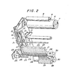
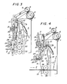
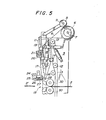
- Figs. 2 through 5 show detailed views of the structure of the laminator main body 1.
- the laminator main body 1 has plate-like support frames 5 (of which one is shown). Between the support frames 5 are rotatably mounted a film supply roll 7 and a take-up roll 9.
- the supply roll 7 carries a continuous film web 6 wound round its circumference.
- the film web 6 on the supply roll 7 is laminated with a protective material 8, which is stripped from the film web 6 and taken up by the take-up roll 9 when the film web 6 is unwound from the supply roll 7.
- a guide rail 10 is fixedly secured to the inner surface of each support frame 5.
- a plate-like block member 11 is slidably carried in each guide rail 10 for vertical movement relative thereto.
- Each of the block members 11 is linked by means of a connecting member 14 to a drive chain 13 that is passed round the periphery of sprockets 12 positioned on the inner surface of each support frame 5. It is so arranged that the operation of the drive chain 13 causes the block member 11 to perform reciprocatory movement toward and away from a tacking station 15 at which the continuous film web 6 is tacked to the panel 2.
- Each of the block members 11 is formed at its lower end with a cam cutout 16.
- a tacking means 17 is movably mounted between the support frames 5 for movement along the path determined by the cam cutouts 16.
- the tacking means 17 is connected at either end to a piston-cylinder system 18 secured to each of the block members 11 for back and forth movement by operation of the piston-cylinder systems 18.
- the tacking means 17 is provided at either end with a rack 19 that extends vertically adjacent to the block member 11.
- a pinion shaft 20 extending between and supported by the block members 11 carries at either end a pinion 21 for rotation in mesh engagement with the rack 19.
- both piston-cylinder systems 18 are operated simultaneously to drive the tacking means 17, the movement of the tacking means 17 is properly guided by the effect of synchronization of the racks 19 with the pinions 21 at the ends of the pinion shaft 20, without tilting to either side.
- the pinion shaft 20 is provided also to act as a pivot shaft for the tacking means 17 when the tacking means 17 moves along the cam cutouts 16 on both sides. In this way, the piston-cylinder systems 18 actuate the tacking means 17 to move toward and away from the panel that is carried onto the tacking station 15.
- the tacking means 17 is so designed that it not only guides the continuous film web 6 but also tacks the web 6 to the panel 2 while holding the web 6 against itself by suction force in the manner to be described later.
- the tacking means 17 is provided at its guide surface with vacuum holes 22 in rows.
- the vacuum holes 22 are connected to a vacuum source (not shown).
- a suitable vacuum control system (not shown) is provided in the vacuum line interconnected between the vacuum holes 22 and -the vacuum source for controlled vacuum supply to the particular rows of vacuum holes 22 so as to accommodate a variety of widths of film web.
- Each of the block members 11 is provided at its lower end with a bracket 23. Between the brackets 23 on both sides extend a guide bar 24 and a rack 25 supported substantially parallel to each other.
- a cutter holder 26 is slidably mounted on the guide bar 24 for movement thereon and has a cutter 27 in the form of a circular rotary blade.
- a motor (not shown) is provided mounted in the cutter holder 26 and is connected to the rotary cutter 27 for rotation thereof. This motor also carries a pinion on its shaft which is engaged in mesh with the rack 25. The operation of the motor causes the cutter 27 to rotate and the cutter holder 26 to move along the guide bar 24 by means of interengagement between the rack 25 and the pinion. In this way, the film web 6 is cut across.
- Separate motors may be provided to respectively shift the cutter holder 26 along the guide bar 24 and rotate the cutter 27.
- the lateral movement of the cutter 27 for cutting across the film web is along a groove 29 formed longitudinally in a cutter guide 28 that extends between the lower ends of the block members 11.
- the front face of the cutter guide 28, that side facing the path of the continuous film web 6 from the supply roll 7, is also formed with vacuum holes 28', in a similar manner to the tacking means 17.
- the vacuum holes 28' are connected to a vacuum source (not shown) and a vacuum supply control means (not shown) is provided in the vacuum line interconnected between the vacuum source and the vacuum holes 28' for selective vacuum supply to the particular rows of the vacuum holes 28' to accommodate a variety of film web widths.
- the cutter is operated by a motor.
- a piston-cylinder system may be employed in conjunction with the pinion and rack arrangement so as to achieve the rotation and lateral movement of the cutter 27.
- a pair of pressure rolls 30, vertically arranged, are provided to extend between the support frames 5 with the gap between the rolls aligned with the path of the blank panel 2.
- the rolls 30 are designed so as to compression stick the film to the panel surface.
- Each support frame 5 is provided at its outer surface with a piston-cylinder system 31 which is in turn connected to a slide base 32.
- the lower end of each of the slide bases 32 supports at least one of the rolls 30, which is the upper roll in this particular embodiment.
- the slide bases 32 are moved up and down by the operation of the piston-cylinder systems 31 along guides 33 which are also secured to the respective support frames 5. This arrangement makes it possible to shift the position of the upper roll relative to the other of the pressure rolls 30 depending on the thickness of the panel 2 to be processed.
- Each of the slide bases 32 is provided with a opening 34.
- a vertical rack 35 is provided on one side of each opening 34.
- a pinion 36 is provided to engage in mesh with the rack 35.
- Between the support frames 5 extends a pinion shaft 37 that goes through the support frames 5 on either side for connection to the pinion 36.
- each of the pressure rolls 30 are provided on the side of the tacking means 17 a pair of film guides 38 extending between the support frames 5.
- the front face of each of the film guides 38 is also provided with rows of vacuum holes 39, in a similar manner to the tacking means 17 and the cutter guide 28.
- the vacuum holes 39 are connected to a vacuum source (not shown) with a vacuum supply control system (not shown) in the vacuum line interconnected between the vacuum holes and the vacuum source for selective vacuum supply to the particular rows of the vacuum holes 39 so as to accommodate a variety of widths of film strip.
- the blank panel 2 to be processed is carried, after heating for enhancement of thermocompression sticking of the film thereto, on the entrance side conveyor assembly 3 to the laminator main body 1.
- the conveyor assembly 3 includes pairs of conveyor rollers 41a, 41b, 41c, 41d, 41e, 41f, and 41g aligned with the path of the panel 2 and a row of properly spaced sensors 40a, 40b, 40c, 40d, 40e, and 40f provided for detection of panels on the conveyor assembly 3 to produce a signal which in turn activates or stops operation of the particular roller pairs for the purpose of orderly feed of panels to the tacking station 15.
- the sensor 40a upon detection of the forward end of the panel 2, produces a signal to activate the roller pairs 41a through 41g which carry the panel 2 toward the tacking station 15.
- the roller pairs 41a through 41g come to a stop.
- the roller pairs 41a and 41b only, situated downstream of the sensor 40c, are stopped whereas the roller pairs 41c through 41g, situated upstream of the sensor 40c, are kept in operation.
- the panel 2 is kept immobile at the tacking station 15 while the panel 2' which follows the panel 2 is kept moving on the conveyor assembly 3.
- the sensor 40c upon sensing the forward end of the panel 2', produces a signal to stop the roller pairs 41c through 41g so that the panel 2' is prevented from bumping into the panel 2.
- the selective operation and proper arrangement of the roller paris in conjunction with sensor means designed for detection of panels make it possible to achieve the controlled feed of panels to the laminator main body at the shortest possible interval with resultant reduction in production time. This arrangement would also be effective particularly for cases where panels to be processed vary in size.
- the tacking means 17 is moved by the action of the piston-cylinder system 18 from its position shown in Fig. 5, with the continuous film web 6 attached to its guide surface by suction, toward the panel 2 and tacks the leading end of the film web 6 to the forward end of the panel 2, as shown in Fig. 3.
- no vacuum has yet been created in the vacuum holes 28' and 39 of the cutter guide 28 and the film guides 38, respectively.
- the tacking means 17 After tacking, the tacking means 17 is moved back to the original retracted position. Simultaneously, the drive chains 13 are set in motion to move the block members 11 away from the tacking station 15 to the retracted position as shown in Fig. 4. Subsequently, the roller pairs 41a through 41g are activated to move the panel 2 into the gap between the pressure rolls 30 and the sticking operation is started by thermocompression of the film web 6 to the surface of the panel 2.
- the sensor 40a upon detection of the rearward end of the panel 2 as it is being advanced toward the pressure rolls 30, produces a signal to set the chains 13 in motion which in turn causes the block members 11 to move toward the tacking station 15.
- the block members 11 move the cutter 27, while rotating, is set to move laterally from one side to the other to cut across the continuous film strip 6. It is so designed that the speed at which the block members 11 move from the retracted position toward the tacking station 15 is equated with the speed of transfer of the roller conveyor assembly 3 at the entrance side (or the circumferential velocity of the pressure rolls 30) and hence the speed of travel of the film web 6.
- the movement of the block members 11 toward the tacking station 15 causes the cutter 27 to move in the same direction and at the same speed as the film web 6, without any difference of relative velocity between them, such that the lateral movement of the cutter 27 produces a precise cut across the film web 6, thereby separating a rectangular film sheet to be stuck on the panel surface.
- the film web 6 is cut (or the length of the individual film sheet) is determined by the time at which the movement of the block member 11 toward the tacking station 15 is initiated. Accordingly, the film sheet of the just required length matching the size of the panel 2 will be obtained by controlling so that the block members 11 start movement toward the panel 2 at a given time after the sensor 40a detects the rearward end of the panel 2 on the conveyor assembly.
- the cutter 27 can complete its transverse slide to cut across the film web during the time of movement of the block members 11 toward the tacking station 15, at any proper cutting speed.
- Means should be incorporated to control precisely where the panel is tacked with the film web and where the film web is cut across in relation to the feed of a panel on the roller conveyor assembly 3.
- a rotary encoder 42 may be employed which receives the signals from the sensors provided on the roller conveyor assembly 3 on the entrance side of the laminator main body.
- the pressure rolls 30 rotate at a constant speed.
- the speed at which the block members 11 approach the tacking station 15 together with the cutter 27 to achieve cutting across the film web should be matched with the circumferential velocity of the pressure rolls 30. In return movement of the block members 11 away from the tacking station 15, however, it is desirable from the viewpoint of operating efficiency to drive them at a greater speed regardless of the circumferential speed of the rolls 30.
- the laminator is built to a simple design that enables the block members to move at two variable speeds, the speed matched with the circumferential speed of the pressure rolls and a greater speed than that speed, without use or addition of a complex drive system.
- the laminator of this embodiment further comprises a motor, a power transmission system operatively connected to the motor for rotating the paired pressure rolls and for moving the block members toward the tacking station at a speed which matches the circumferential velocity of the pressure rolls, a drive mechanism for causing the block members to move away from the tacking station, and a clutch means for releasably connecting the block members to the power transmission system.
- the drive system may include a piston-cylinder means.
- the piston-cylinder means may be secured at one end to the endless drive chains on which the block members are supported.
- any other suitable drive means may be used with or without direct connection to the block members.
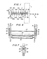
- Fig. 8 is a schematic diagram of this embodiment, with the less important parts omitted for brevity's sake, in which the main parts are built to be substantially equal in overall structure and function to their counterparts in the previous embodiment shown in Figs. 2 through 5, except for the drive system, the power transmission system, and the rotary shafts.
- the laminator main body has a pair of block members 43 and 44 disposed vertically for movement toward and away from the middle of the laminator.
- Each of the block members 43 and 44 is supported at both ends on a pair of common endless drive chains 48 and 49 which are passed round a pair of sprockets 46 and 47 at the upper end of the laminator and another pair of sprockets 50 and 51 at the lower end of the laminator.
- the sprockets 46 and 47 are provided on opposite ends of a shaft 45 rotatably mounted on the laminator.
- the sprockets 50 and 51 may also be provided on a shaft rotatably mounted on the laminator or, as shown in Fig.
- FIG. 8 may be mounted on the laminator without a shaft.
- the rotary shaft 45 and the lower sprockets 50 and 51 are mounted on the support frame (not shown) for free rotation.
- both of the block members 43 and 44 are depicted to resemble in shape a tacking means.
- this representation is aimed at simplifying the actual intricacies of the structure so that the operation of the system of this particular embodiment can be easily understood.
- the block members 43 and 44 of this embodiment are in fact identical in configuration to their counterpart in the previous embodiment shown in Figs. 2 through 5, each also carrying tacking means similar to the tacking means 11 identified in the same figures. As shown in Fig.
- the upper block member 43 is supported through a connecting means 52 to the drive chains 48 and 49 on this side.
- the lower block member 44 is supported through connecting means 53 to the drive chains 48 and 49 on the other side.
- the rotary shaft 45 carries another sprocket on its extended leftmost end.
- a clutch 55 is mounted between the sprockets 54 and 46 on the shaft 45. The rotation of the sprocket 54 is selectively transmitted to the sprocket 46 by operation of the clutch 55.
- the sprocket 54 is driven by a motor 57 through an endless drive chain 59 that is passed round the sprocket 54 and a sprocket 58 fixed on the shaft of the motor 57.
- the drive chain 59 is also passed round a sprocket 56 fixed on the shaft of one of the paired pressure rolls 30, so that the motor 57 can drive the rolls 30.
- the arrangement is such that, when the clutch 55 is in the engaged position, the motor 57 drives the rolls 30 and, at the same time, the rotary shaft 45 through the speocket 54, causing the block members 43 and 44 to move toward each other through the sprocket 46.
- the speed of movement of each of the block members is matched with the circumferential velocity of the rolls 30 through a speed changer (not shown) which is mounted at a suitable location in the driving mechanism.
- a speed changer (not shown) which is mounted at a suitable location in the driving mechanism.
- the motor 57 drives the rolls 30 alone.
- a separate drive system operates the block members 43 and 44 in their movement away from each other.
- this drive system is a piston-cylinder system 60.
- the piston-cylinder system 60 is secured at its lower end to a fixed base and is connected at its upper end to the drive chain 48 through a connecting means 61. With this arrangement, operation of the piston-cylinder system 60, with the clutch 55 set in the released position, causes the block members 43 and 44 to move away from each other at a speed different from the circumferential velocity of the rolls 30.
- the rotary shaft 45 may be provided on its rightmost end with a brake 62 for taking up the backlash.
- the clutch 55 is normally set in the released position.
- the tacking means supported by each block member which is positioned adjacent to the tacking station is caused to move toward the panel. Then, the tacking means tacks the forward end of the panel surface with the leading end of the continuous film web.
- the tacking means are retracted and the piston-cylinder system 60 is actuated to move the block members 43 and 44 together with the tacking means away from the tacking station at a relatively greater speed than that at which they are moved to the tacking station.
- the panel tacked with the film web is then moved on the conveyor means and the film is started to be stuck on the panel surface between the pressure rolls 30 which are rotated at a constant circumferential velocity by the motor 57.
- a signal for initiation of the film web cutting operation causes the piston-cylinder system 60 to shift to the non-actuation position.
- the clutch 55 is actuated to engage the sprocket 54 to the sprocket 46, causing the block members 43 and 44 to start moving toward the tacking station at a speed matched with the circumferential velocity of the rolls 30.
- the cutter performs transverse movement to cut across the film web, separating an individual film sheet of predetermined length matching the size of the panel.
- the clutch 55 is released and the block members 43, 44 cease to move.
- the pressure rolls 30 still continue to rotate so as to stick the remaining part of the film sheet on the panel surface to complete the laminated panel.
- the tacking station the same process is repeated, starting with the tacking operation.
- the individual film sheet to be compression stuck on the panel surface is cut to just the required length from the continuous film web and, in addition, this cutting is effected while the film is stuck on the panel surface, so that the additional finishing operations as well as wastage of film can be eliminated.
- the compression sticking of film on the panel surface is effected with a continuous sweep of operation, without the pressure rolls temporarily stopping rotation midway on the panel during the sticking operation, thus producing a uniform surface condition on the film sheet.
- the cutter used for cutting film web in this invention may be any known cutting tool, although a circular cutting blade is mentioned in the above description.
- the piston-cylinder system and the drive chain and sprocket system may respectively be replaced by suitable known drive means.
- the laminator of the present invention is designed such that the components of the laminator are provided substantially in symmetry with respect to the conveyor means for feeding panels.
- the laminator can be built with a single unit of lamination means.
- the laminator main body may be mounted on a slidable base on rails so that it can be bodily pulled out from position to one side. This construction would be convenient when the laminator is required for maintenance or repair.
- the tacking means, the cutter and the film guide respectively may have their vacuum holes connected to a separate vacuum source or, more preferably, to a common vacuum source (such as a vacuum pump).
- the vacuum holes are arranged in columns, the center column disposed to correspond to the longitudinal centerline of the continuous film web and the other columns are distributed over the width of the film web, with every one or more columns of vacuum holes being connected through a separate branch vacuum line to the vacuum source.
- Each of the branch vacuum lines is provided with a separate control valve provided between the vacuum holes and the source. All of the branch vacuum lines respectively of the tacking means, the cutter guide and the film guide are made to converge to a separate main vacuum line which is also provided with a control valve. These control valves are individually operated to create a vacuum.
- the control valves in the main vacuum lines connected to the film guide and the cutter guide are kept closed so that a vacuum is created in the vacuum holes of the tacking means alone.
- the main vacuum lines may be connected to the common vacuum source through a common primary vacuum line.
Landscapes
- Engineering & Computer Science (AREA)
- Manufacturing & Machinery (AREA)
- Software Systems (AREA)
- Theoretical Computer Science (AREA)
- Physics & Mathematics (AREA)
- General Engineering & Computer Science (AREA)
- General Physics & Mathematics (AREA)
- Laminated Bodies (AREA)
- Lining Or Joining Of Plastics Or The Like (AREA)
Applications Claiming Priority (4)
| Application Number | Priority Date | Filing Date | Title |
|---|---|---|---|
| JP58082241A JPS6085927A (ja) | 1983-05-11 | 1983-05-11 | パネルにフイルムシートを付着させる方法およびそれに用いるラミネータ |
| JP82241/83 | 1983-05-11 | ||
| JP58184659A JPS6076341A (ja) | 1983-10-03 | 1983-10-03 | パネルにフイルムシ−トを付着させるためのラミネ−タ |
| JP184659/83 | 1983-10-03 |
Publications (3)
| Publication Number | Publication Date |
|---|---|
| EP0125584A2 true EP0125584A2 (fr) | 1984-11-21 |
| EP0125584A3 EP0125584A3 (en) | 1986-10-01 |
| EP0125584B1 EP0125584B1 (fr) | 1989-11-02 |
Family
ID=26423255
Family Applications (1)
| Application Number | Title | Priority Date | Filing Date |
|---|---|---|---|
| EP19840105062 Expired EP0125584B1 (fr) | 1983-05-11 | 1984-05-04 | Appareil de fixation d'une feuille sous forme de film sur une surface de panneau |
Country Status (5)
| Country | Link |
|---|---|
| US (2) | US4659419A (fr) |
| EP (1) | EP0125584B1 (fr) |
| KR (1) | KR890000655B1 (fr) |
| CA (1) | CA1245962A (fr) |
| DE (1) | DE3480332D1 (fr) |
Cited By (19)
| Publication number | Priority date | Publication date | Assignee | Title |
|---|---|---|---|---|
| EP0213555A3 (fr) * | 1985-09-02 | 1988-05-25 | BASF Aktiengesellschaft | Appareil pour découper des bandes en matière photorésistante en feuilles de grandeur définie et laminage précis et sans plis des feuilles sur un support flexible ou rigide |
| EP0264680A3 (en) * | 1986-10-01 | 1989-10-25 | Somar Corporation | Laminator |
| EP0244817A3 (en) * | 1986-05-07 | 1989-10-25 | Somar Corporation | Laminator |
| EP0401701A1 (fr) * | 1989-06-04 | 1990-12-12 | Somar Corporation | Dispositif de coupe ajustable d'une feuille |
| EP0314036A3 (fr) * | 1987-10-28 | 1991-07-03 | Hoechst Aktiengesellschaft | Appareil pour laminer et couper des bandes photorésists |
| EP0350060A3 (fr) * | 1988-07-07 | 1991-07-24 | Somar Corporation | Elément d'alimentation d'un film mince pour une machine de revêtement par films minces |
| EP0360269A3 (fr) * | 1988-09-22 | 1991-08-07 | Somar Corporation | Procédé et appareil pour faire adhérer un film mince |
| EP0426931A3 (en) * | 1989-11-04 | 1991-08-07 | Somar Corporation | Film bonding method and apparatus for performing same |
| DE4103867A1 (de) * | 1990-05-15 | 1991-11-21 | Somar Corp | Laminiermaschine |
| EP0436065A3 (en) * | 1989-12-31 | 1991-12-04 | Somar Corporation | Method and apparatus for automatically bonding film to a substrate and cutting the film to desired size |
| EP0460621A1 (fr) * | 1990-06-04 | 1991-12-11 | Hakuto Co., Ltd. | Dispositif de laminage à vide |
| EP0544977A1 (fr) * | 1991-12-03 | 1993-06-09 | Hakuto Co., Ltd. | Dispositif et procédé pour la lamination d'un film sur un substrat |
| EP0547327A1 (fr) * | 1991-12-13 | 1993-06-23 | Somar Corporation | Machine et procédé d'application d'un film |
| EP1029649A1 (fr) * | 1999-02-18 | 2000-08-23 | Sanei Giken Co., Ltd. | Dispositif de laminage |
| CN106541674A (zh) * | 2016-11-04 | 2017-03-29 | 深圳市龙锋泰自动化有限公司 | 全自动玻璃在线覆膜方法 |
| CN107160667A (zh) * | 2017-05-08 | 2017-09-15 | 安徽颍瑞源焊管科技有限公司 | 一种高精度集成墙面板覆膜设备 |
| CN107599423A (zh) * | 2017-09-30 | 2018-01-19 | 浙江大学华南工业技术研究院 | 一种型腔式包覆机 |
| CN110524864A (zh) * | 2019-09-03 | 2019-12-03 | 毛庆 | 一种利用间歇性运动原理的铝板覆膜设备 |
| CN113320738A (zh) * | 2021-06-07 | 2021-08-31 | 温辉棣 | 一种led显示屏加工生产用显示屏辅助覆膜设备 |
Families Citing this family (33)
| Publication number | Priority date | Publication date | Assignee | Title |
|---|---|---|---|---|
| JPS61280916A (ja) * | 1985-06-07 | 1986-12-11 | Somar Corp | ラミネ−タ |
| WO1986007302A1 (fr) * | 1985-06-07 | 1986-12-18 | Somar Corporation | Procede et dispositif de poinçonnage de pellicules pour appareils d'encollage de pellicules |
| JPS6299045A (ja) * | 1985-10-22 | 1987-05-08 | Somar Corp | 基板送り装置 |
| JPS6299044A (ja) * | 1985-10-22 | 1987-05-08 | Somar Corp | 基板の搬送保持装置 |
| JPS63200991A (ja) * | 1987-02-12 | 1988-08-19 | ソマ−ル株式会社 | 薄膜張付装置 |
| JPH0798362B2 (ja) * | 1987-02-24 | 1995-10-25 | ソマ−ル株式会社 | 薄膜の張付方法 |
| DE3737946A1 (de) * | 1987-11-07 | 1989-06-08 | Wolfgang Anger | Cutsheet-lamination mittels eines laminators |
| DE3819845A1 (de) * | 1988-06-10 | 1990-02-01 | Minnesota Mining & Mfg | Verfahren zum definierten aufbringen von abschnitten eines bandes auf eine oberflaeche und vorrichtung zur durchfuehrung dieses verfahrens |
| US5102491A (en) * | 1988-12-09 | 1992-04-07 | Morton International, Inc. | Wet lamination process and apparatus |
| US4976817A (en) * | 1988-12-09 | 1990-12-11 | Morton International, Inc. | Wet lamination process and apparatus |
| US5192385A (en) * | 1989-05-01 | 1993-03-09 | Minnesota Mining And Manufacturing Company | Method for the application of lengths of tape to a surface |
| JPH037343A (ja) * | 1989-06-04 | 1991-01-14 | Somar Corp | 薄膜張付用薄膜ガイド装置 |
| JPH03270897A (ja) * | 1990-03-19 | 1991-12-03 | Somar Corp | フィルム張付方法及びその実施装置 |
| JPH0412849A (ja) * | 1990-04-28 | 1992-01-17 | Somar Corp | ラミネータ |
| US5653846A (en) * | 1991-11-11 | 1997-08-05 | Canon Aptex Inc. | Laminating apparatus |
| US6826987B1 (en) * | 1996-08-14 | 2004-12-07 | International Business Machines Corporation | Method for cutting movable web material |
| IT1313117B1 (it) * | 1999-08-25 | 2002-06-17 | Morton Int Inc | Apparecchiatura di applicazione a vuoto dotata di mezzi trasportatorie procedimento per applicare un resist a film secco ad un pannello di |
| IT1315026B1 (it) * | 2000-08-10 | 2003-01-27 | Bisazza Spa | Dispositivo per la produzione di pannelli di mosaico, relativoprocedimento e pannelli di mosaico cosi' ottenuti. |
| KR20020026080A (ko) * | 2000-09-30 | 2002-04-06 | 추후제출 | 필름부착방법 |
| US6698487B2 (en) | 2000-11-15 | 2004-03-02 | Xyron, Inc. | Master processing apparatus |
| WO2002092343A2 (fr) * | 2001-05-16 | 2002-11-21 | Xyron, Inc. | Appareil de pressage/collage d'article comprenant un detecteur de cartouche reglant le fonctionnement et/ou produisant un chauffage ameliore et/ou une decoupe amelioree |
| US6786265B1 (en) | 2002-01-03 | 2004-09-07 | Alex J. Kaye | Laminating machine |
| GB2389816B (en) * | 2002-05-17 | 2005-10-12 | Hewlett Packard Co | Printing apparatus and method |
| ATE430655T1 (de) * | 2002-06-10 | 2009-05-15 | Kingspan Res & Dev Ltd | Verfahren zur herstellung von dämmplatten |
| US7361249B2 (en) * | 2002-12-05 | 2008-04-22 | Multimedia Games, Inc. | Apparatus for applying a removable cover to a ticket substrate |
| US8453695B2 (en) * | 2006-10-30 | 2013-06-04 | Avery Dennison Retail Information Services, Llc | Portable applicator |
| US9731489B2 (en) | 2013-05-29 | 2017-08-15 | H.B. Fuller Company | Material application system |
| US9205680B2 (en) * | 2014-01-16 | 2015-12-08 | Memjet Technology Ltd. | Printer having regenerative intermediary drive |
| CA3091829A1 (fr) | 2018-03-05 | 2019-09-12 | H.B. Fuller Company | Systemes et procedes d'application de materiau en bande |
| CN108527832B (zh) * | 2018-04-18 | 2023-11-28 | 深圳市承熹机电设备有限公司 | 贴合方法及贴合机 |
| CN110014640B (zh) * | 2019-05-27 | 2023-12-26 | 温州光明印刷机械有限公司 | 双用覆膜压纹一体机 |
| KR102297203B1 (ko) * | 2020-07-02 | 2021-09-03 | 주식회사 보백씨엔에스 | 배터리 보호용 pu-폼 가공장치 |
| CN112248610A (zh) * | 2020-11-13 | 2021-01-22 | 常州杰仕特网印机械有限公司 | 玻璃板覆膜机 |
Family Cites Families (16)
| Publication number | Priority date | Publication date | Assignee | Title |
|---|---|---|---|---|
| US2732880A (en) * | 1956-01-31 | Sheeting to metal plates | ||
| US2721669A (en) * | 1950-04-21 | 1955-10-25 | Clifford D Keely | Machine for applying gummed tape to box blanks |
| US2721670A (en) * | 1952-01-11 | 1955-10-25 | Clifford D Keely | Box blank taping machine |
| US2783839A (en) * | 1954-02-03 | 1957-03-05 | Eastman Kodak Co | Film chopping mechanism |
| US3421963A (en) * | 1965-08-30 | 1969-01-14 | Indian National Bank Of Nashua | Apparatus for applying tape |
| US3438835A (en) * | 1966-03-04 | 1969-04-15 | Polaroid Corp | Apparatus for laminating and cutting including a pair of rollers with cutting edges |
| US3577297A (en) * | 1969-01-27 | 1971-05-04 | Rohr Corp | Taping apparatus and method |
| US3658629A (en) * | 1970-02-27 | 1972-04-25 | Ibm | Photopolymer resist sheet laminator |
| US3886033A (en) * | 1972-02-25 | 1975-05-27 | Continental Can Co | Method and apparatus for applying a cutting strip to a container |
| US4025380A (en) * | 1975-07-24 | 1977-05-24 | International Business Machines Corporation | Variable resist laminator |
| US4274903A (en) * | 1979-07-13 | 1981-06-23 | Mock Vernon A | High speed programmable pressure-sensitive transfer tape applicator |
| GB2101519B (en) * | 1981-06-22 | 1986-03-19 | Vought Corp | Apparatus for tape laying and manufacture of composite structures |
| IT1210033B (it) * | 1982-02-10 | 1989-09-06 | Bc Chem Srl | Macchina per applicare una porzione di film fotosensibile su almeno unafaccia di una lastra piana avente una estensione superficiale maggiore di detta porzione |
| DE3216970A1 (de) * | 1982-05-06 | 1983-11-10 | Peter 7072 Heubach Renz | Einrichtung zum kaschieren von boegen mit kunststoff-folie |
| US4491492A (en) * | 1982-10-28 | 1985-01-01 | At&T Technologies, Inc. | Methods of and apparatus for applying a sheet to a rigid board |
| JPS6071229A (ja) * | 1983-09-29 | 1985-04-23 | Somar Corp | オ−トラミネ−タ |
-
1984
- 1984-05-01 US US06/607,114 patent/US4659419A/en not_active Expired - Lifetime
- 1984-05-03 CA CA000453479A patent/CA1245962A/fr not_active Expired
- 1984-05-04 EP EP19840105062 patent/EP0125584B1/fr not_active Expired
- 1984-05-04 DE DE8484105062T patent/DE3480332D1/de not_active Expired
- 1984-05-11 KR KR1019840002538A patent/KR890000655B1/ko not_active Expired
-
1986
- 1986-09-17 US US06908233 patent/US4743325C1/en not_active Expired - Lifetime
Cited By (24)
| Publication number | Priority date | Publication date | Assignee | Title |
|---|---|---|---|---|
| EP0213555A3 (fr) * | 1985-09-02 | 1988-05-25 | BASF Aktiengesellschaft | Appareil pour découper des bandes en matière photorésistante en feuilles de grandeur définie et laminage précis et sans plis des feuilles sur un support flexible ou rigide |
| EP0244817A3 (en) * | 1986-05-07 | 1989-10-25 | Somar Corporation | Laminator |
| EP0264680A3 (en) * | 1986-10-01 | 1989-10-25 | Somar Corporation | Laminator |
| EP0314036A3 (fr) * | 1987-10-28 | 1991-07-03 | Hoechst Aktiengesellschaft | Appareil pour laminer et couper des bandes photorésists |
| EP0350060A3 (fr) * | 1988-07-07 | 1991-07-24 | Somar Corporation | Elément d'alimentation d'un film mince pour une machine de revêtement par films minces |
| EP0360269A3 (fr) * | 1988-09-22 | 1991-08-07 | Somar Corporation | Procédé et appareil pour faire adhérer un film mince |
| EP0401701A1 (fr) * | 1989-06-04 | 1990-12-12 | Somar Corporation | Dispositif de coupe ajustable d'une feuille |
| US5162071A (en) * | 1989-06-04 | 1992-11-10 | Somar Corporation | Adjustable film cutoff unit |
| EP0426931A3 (en) * | 1989-11-04 | 1991-08-07 | Somar Corporation | Film bonding method and apparatus for performing same |
| EP0436065A3 (en) * | 1989-12-31 | 1991-12-04 | Somar Corporation | Method and apparatus for automatically bonding film to a substrate and cutting the film to desired size |
| DE4103867A1 (de) * | 1990-05-15 | 1991-11-21 | Somar Corp | Laminiermaschine |
| EP0460621A1 (fr) * | 1990-06-04 | 1991-12-11 | Hakuto Co., Ltd. | Dispositif de laminage à vide |
| EP0544977A1 (fr) * | 1991-12-03 | 1993-06-09 | Hakuto Co., Ltd. | Dispositif et procédé pour la lamination d'un film sur un substrat |
| EP0547327A1 (fr) * | 1991-12-13 | 1993-06-23 | Somar Corporation | Machine et procédé d'application d'un film |
| US5356501A (en) * | 1991-12-13 | 1994-10-18 | Somar Corporation | Film applying method and film applying apparatus |
| EP1029649A1 (fr) * | 1999-02-18 | 2000-08-23 | Sanei Giken Co., Ltd. | Dispositif de laminage |
| US6367532B1 (en) | 1999-02-18 | 2002-04-09 | Sanei Giken Co., Ltd. | Laminator |
| CN106541674A (zh) * | 2016-11-04 | 2017-03-29 | 深圳市龙锋泰自动化有限公司 | 全自动玻璃在线覆膜方法 |
| CN106541674B (zh) * | 2016-11-04 | 2017-12-01 | 深圳市龙锋泰自动化有限公司 | 全自动玻璃在线覆膜方法 |
| CN107160667A (zh) * | 2017-05-08 | 2017-09-15 | 安徽颍瑞源焊管科技有限公司 | 一种高精度集成墙面板覆膜设备 |
| CN107599423A (zh) * | 2017-09-30 | 2018-01-19 | 浙江大学华南工业技术研究院 | 一种型腔式包覆机 |
| CN110524864A (zh) * | 2019-09-03 | 2019-12-03 | 毛庆 | 一种利用间歇性运动原理的铝板覆膜设备 |
| CN110524864B (zh) * | 2019-09-03 | 2020-06-26 | 济南宏泰铝业有限公司 | 一种利用间歇性运动原理的铝板覆膜设备 |
| CN113320738A (zh) * | 2021-06-07 | 2021-08-31 | 温辉棣 | 一种led显示屏加工生产用显示屏辅助覆膜设备 |
Also Published As
| Publication number | Publication date |
|---|---|
| EP0125584B1 (fr) | 1989-11-02 |
| KR850000166A (ko) | 1985-02-25 |
| EP0125584A3 (en) | 1986-10-01 |
| CA1245962A (fr) | 1988-12-06 |
| US4659419A (en) | 1987-04-21 |
| US4743325C1 (en) | 2002-09-10 |
| DE3480332D1 (en) | 1989-12-07 |
| US4743325A (en) | 1988-05-10 |
| KR890000655B1 (ko) | 1989-03-22 |
Similar Documents
| Publication | Publication Date | Title |
|---|---|---|
| US4659419A (en) | Laminator for sticking film sheet on panel surface | |
| EP0744286B1 (fr) | Méthode d'application de feuilles et dispositif pour la mise en oeuvre | |
| KR101757428B1 (ko) | 광학 필름의 접속 장치 | |
| US4961808A (en) | High lamination speed automatic laminator | |
| US4505772A (en) | Apparatus for laminating sheets with a plastic film | |
| US4025380A (en) | Variable resist laminator | |
| US4470589A (en) | Method and apparatus for feeding and laminating sheets | |
| CA3077156C (fr) | Transporteur a scie a rouleaux de tissu avec coupe a commande de piste independante et a longueur d'etendue de transporteur variable | |
| EP0426931B1 (fr) | Procédé pour faire adhérer un film et appareil pour sa réalisation | |
| US3674590A (en) | Means and method for applying facing strips to cores | |
| US5409340A (en) | Spine strip formation and feed method and apparatus | |
| US4882006A (en) | System for stretching and severing strip-like resin sheet | |
| EP0436065A2 (fr) | Procédé et dispositif pour coller automatiquement des films à un substrat, et pour découper des films | |
| EP1547927A2 (fr) | Dispositif d'alimentation et de coupe de bande pour machine d'emballage | |
| US6003417A (en) | Indexer for moving food along a processing line in a precise manner | |
| US5107659A (en) | Method of and apparatus for continuous bakery product wrapping | |
| EP0550811B1 (fr) | Appareil pour la lamination humide | |
| JP4010613B2 (ja) | フィルム切断装置 | |
| EP0547327B1 (fr) | Machine et procédé d'application d'un film | |
| US4170170A (en) | Apparatus for fabricating and assembling multi-cell partitions | |
| JPS6249169B2 (fr) | ||
| CN113320126B (zh) | 一种能够快速换带的编管机及其使用方法 | |
| JPS646919B2 (fr) | ||
| HK1015130A (en) | Film applying method and apparatus for carrying out the same | |
| CN118700604A (zh) | 一种帘布自动贴合方法 |
Legal Events
| Date | Code | Title | Description |
|---|---|---|---|
| PUAI | Public reference made under article 153(3) epc to a published international application that has entered the european phase |
Free format text: ORIGINAL CODE: 0009012 |
|
| AK | Designated contracting states |
Designated state(s): BE CH DE FR GB IT LI SE |
|
| PUAL | Search report despatched |
Free format text: ORIGINAL CODE: 0009013 |
|
| AK | Designated contracting states |
Kind code of ref document: A3 Designated state(s): BE CH DE FR GB IT LI SE |
|
| 17P | Request for examination filed |
Effective date: 19861124 |
|
| 17Q | First examination report despatched |
Effective date: 19880309 |
|
| ITF | It: translation for a ep patent filed | ||
| GRAA | (expected) grant |
Free format text: ORIGINAL CODE: 0009210 |
|
| AK | Designated contracting states |
Kind code of ref document: B1 Designated state(s): BE CH DE FR GB IT LI SE |
|
| REF | Corresponds to: |
Ref document number: 3480332 Country of ref document: DE Date of ref document: 19891207 |
|
| ET | Fr: translation filed | ||
| PLBE | No opposition filed within time limit |
Free format text: ORIGINAL CODE: 0009261 |
|
| STAA | Information on the status of an ep patent application or granted ep patent |
Free format text: STATUS: NO OPPOSITION FILED WITHIN TIME LIMIT |
|
| 26N | No opposition filed | ||
| ITTA | It: last paid annual fee | ||
| EAL | Se: european patent in force in sweden |
Ref document number: 84105062.8 |
|
| PGFP | Annual fee paid to national office [announced via postgrant information from national office to epo] |
Ref country code: SE Payment date: 20010323 Year of fee payment: 18 |
|
| PGFP | Annual fee paid to national office [announced via postgrant information from national office to epo] |
Ref country code: BE Payment date: 20010410 Year of fee payment: 18 |
|
| PGFP | Annual fee paid to national office [announced via postgrant information from national office to epo] |
Ref country code: CH Payment date: 20010430 Year of fee payment: 18 |
|
| REG | Reference to a national code |
Ref country code: GB Ref legal event code: IF02 |
|
| PGFP | Annual fee paid to national office [announced via postgrant information from national office to epo] |
Ref country code: FR Payment date: 20020417 Year of fee payment: 19 |
|
| PGFP | Annual fee paid to national office [announced via postgrant information from national office to epo] |
Ref country code: GB Payment date: 20020424 Year of fee payment: 19 |
|
| PG25 | Lapsed in a contracting state [announced via postgrant information from national office to epo] |
Ref country code: SE Free format text: LAPSE BECAUSE OF NON-PAYMENT OF DUE FEES Effective date: 20020505 |
|
| PG25 | Lapsed in a contracting state [announced via postgrant information from national office to epo] |
Ref country code: LI Free format text: LAPSE BECAUSE OF NON-PAYMENT OF DUE FEES Effective date: 20020531 Ref country code: CH Free format text: LAPSE BECAUSE OF NON-PAYMENT OF DUE FEES Effective date: 20020531 Ref country code: BE Free format text: LAPSE BECAUSE OF NON-PAYMENT OF DUE FEES Effective date: 20020531 |
|
| EUG | Se: european patent has lapsed | ||
| REG | Reference to a national code |
Ref country code: CH Ref legal event code: PL |
|
| PG25 | Lapsed in a contracting state [announced via postgrant information from national office to epo] |
Ref country code: GB Free format text: LAPSE BECAUSE OF NON-PAYMENT OF DUE FEES Effective date: 20030504 |
|
| PGFP | Annual fee paid to national office [announced via postgrant information from national office to epo] |
Ref country code: DE Payment date: 20030730 Year of fee payment: 20 |
|
| GBPC | Gb: european patent ceased through non-payment of renewal fee |
Effective date: 20030504 |
|
| PG25 | Lapsed in a contracting state [announced via postgrant information from national office to epo] |
Ref country code: FR Free format text: LAPSE BECAUSE OF NON-PAYMENT OF DUE FEES Effective date: 20040130 |
|
| REG | Reference to a national code |
Ref country code: FR Ref legal event code: ST |