EP0125669A2 - Universalaufstellung eines Tastenfeldes und verstellbarer Tastenfeldträger - Google Patents
Universalaufstellung eines Tastenfeldes und verstellbarer Tastenfeldträger Download PDFInfo
- Publication number
- EP0125669A2 EP0125669A2 EP84105396A EP84105396A EP0125669A2 EP 0125669 A2 EP0125669 A2 EP 0125669A2 EP 84105396 A EP84105396 A EP 84105396A EP 84105396 A EP84105396 A EP 84105396A EP 0125669 A2 EP0125669 A2 EP 0125669A2
- Authority
- EP
- European Patent Office
- Prior art keywords
- keyboard
- mounting plate
- plate
- movement
- mount
- Prior art date
- Legal status (The legal status is an assumption and is not a legal conclusion. Google has not performed a legal analysis and makes no representation as to the accuracy of the status listed.)
- Withdrawn
Links
Images



Classifications
-
- F—MECHANICAL ENGINEERING; LIGHTING; HEATING; WEAPONS; BLASTING
- F16—ENGINEERING ELEMENTS AND UNITS; GENERAL MEASURES FOR PRODUCING AND MAINTAINING EFFECTIVE FUNCTIONING OF MACHINES OR INSTALLATIONS; THERMAL INSULATION IN GENERAL
- F16M—FRAMES, CASINGS OR BEDS OF ENGINES, MACHINES OR APPARATUS, NOT SPECIFIC TO ENGINES, MACHINES OR APPARATUS PROVIDED FOR ELSEWHERE; STANDS; SUPPORTS
- F16M13/00—Other supports for positioning apparatus or articles; Means for steadying hand-held apparatus or articles
- F16M13/02—Other supports for positioning apparatus or articles; Means for steadying hand-held apparatus or articles for supporting on, or attaching to, an object, e.g. tree, gate, window-frame, cycle
-
- A—HUMAN NECESSITIES
- A47—FURNITURE; DOMESTIC ARTICLES OR APPLIANCES; COFFEE MILLS; SPICE MILLS; SUCTION CLEANERS IN GENERAL
- A47B—TABLES; DESKS; OFFICE FURNITURE; CABINETS; DRAWERS; GENERAL DETAILS OF FURNITURE
- A47B21/00—Tables or desks for office equipment, e.g. typewriters, keyboards
- A47B21/03—Tables or desks for office equipment, e.g. typewriters, keyboards with substantially horizontally extensible or adjustable parts other than drawers, e.g. leaves
- A47B21/0314—Platforms for supporting office equipment
-
- F—MECHANICAL ENGINEERING; LIGHTING; HEATING; WEAPONS; BLASTING
- F16—ENGINEERING ELEMENTS AND UNITS; GENERAL MEASURES FOR PRODUCING AND MAINTAINING EFFECTIVE FUNCTIONING OF MACHINES OR INSTALLATIONS; THERMAL INSULATION IN GENERAL
- F16M—FRAMES, CASINGS OR BEDS OF ENGINES, MACHINES OR APPARATUS, NOT SPECIFIC TO ENGINES, MACHINES OR APPARATUS PROVIDED FOR ELSEWHERE; STANDS; SUPPORTS
- F16M11/00—Stands or trestles as supports for apparatus or articles placed thereon ; Stands for scientific apparatus such as gravitational force meters
- F16M11/02—Heads
- F16M11/04—Means for attachment of apparatus; Means allowing adjustment of the apparatus relatively to the stand
- F16M11/043—Allowing translations
- F16M11/048—Allowing translations adapted to forward-backward translation movement
-
- F—MECHANICAL ENGINEERING; LIGHTING; HEATING; WEAPONS; BLASTING
- F16—ENGINEERING ELEMENTS AND UNITS; GENERAL MEASURES FOR PRODUCING AND MAINTAINING EFFECTIVE FUNCTIONING OF MACHINES OR INSTALLATIONS; THERMAL INSULATION IN GENERAL
- F16M—FRAMES, CASINGS OR BEDS OF ENGINES, MACHINES OR APPARATUS, NOT SPECIFIC TO ENGINES, MACHINES OR APPARATUS PROVIDED FOR ELSEWHERE; STANDS; SUPPORTS
- F16M11/00—Stands or trestles as supports for apparatus or articles placed thereon ; Stands for scientific apparatus such as gravitational force meters
- F16M11/20—Undercarriages with or without wheels
- F16M11/2007—Undercarriages with or without wheels comprising means allowing pivoting adjustment
- F16M11/2035—Undercarriages with or without wheels comprising means allowing pivoting adjustment in more than one direction
- F16M11/2064—Undercarriages with or without wheels comprising means allowing pivoting adjustment in more than one direction for tilting and panning
-
- F—MECHANICAL ENGINEERING; LIGHTING; HEATING; WEAPONS; BLASTING
- F16—ENGINEERING ELEMENTS AND UNITS; GENERAL MEASURES FOR PRODUCING AND MAINTAINING EFFECTIVE FUNCTIONING OF MACHINES OR INSTALLATIONS; THERMAL INSULATION IN GENERAL
- F16M—FRAMES, CASINGS OR BEDS OF ENGINES, MACHINES OR APPARATUS, NOT SPECIFIC TO ENGINES, MACHINES OR APPARATUS PROVIDED FOR ELSEWHERE; STANDS; SUPPORTS
- F16M11/00—Stands or trestles as supports for apparatus or articles placed thereon ; Stands for scientific apparatus such as gravitational force meters
- F16M11/20—Undercarriages with or without wheels
- F16M11/2092—Undercarriages with or without wheels comprising means allowing depth adjustment, i.e. forward-backward translation of the head relatively to the undercarriage
-
- F—MECHANICAL ENGINEERING; LIGHTING; HEATING; WEAPONS; BLASTING
- F16—ENGINEERING ELEMENTS AND UNITS; GENERAL MEASURES FOR PRODUCING AND MAINTAINING EFFECTIVE FUNCTIONING OF MACHINES OR INSTALLATIONS; THERMAL INSULATION IN GENERAL
- F16M—FRAMES, CASINGS OR BEDS OF ENGINES, MACHINES OR APPARATUS, NOT SPECIFIC TO ENGINES, MACHINES OR APPARATUS PROVIDED FOR ELSEWHERE; STANDS; SUPPORTS
- F16M11/00—Stands or trestles as supports for apparatus or articles placed thereon ; Stands for scientific apparatus such as gravitational force meters
- F16M11/20—Undercarriages with or without wheels
- F16M11/24—Undercarriages with or without wheels changeable in height or length of legs, also for transport only, e.g. by means of tubes screwed into each other
-
- A—HUMAN NECESSITIES
- A47—FURNITURE; DOMESTIC ARTICLES OR APPLIANCES; COFFEE MILLS; SPICE MILLS; SUCTION CLEANERS IN GENERAL
- A47B—TABLES; DESKS; OFFICE FURNITURE; CABINETS; DRAWERS; GENERAL DETAILS OF FURNITURE
- A47B21/00—Tables or desks for office equipment, e.g. typewriters, keyboards
- A47B21/03—Tables or desks for office equipment, e.g. typewriters, keyboards with substantially horizontally extensible or adjustable parts other than drawers, e.g. leaves
- A47B21/0314—Platforms for supporting office equipment
- A47B2021/0321—Keyboard supports
-
- A—HUMAN NECESSITIES
- A47—FURNITURE; DOMESTIC ARTICLES OR APPLIANCES; COFFEE MILLS; SPICE MILLS; SUCTION CLEANERS IN GENERAL
- A47B—TABLES; DESKS; OFFICE FURNITURE; CABINETS; DRAWERS; GENERAL DETAILS OF FURNITURE
- A47B21/00—Tables or desks for office equipment, e.g. typewriters, keyboards
- A47B21/03—Tables or desks for office equipment, e.g. typewriters, keyboards with substantially horizontally extensible or adjustable parts other than drawers, e.g. leaves
- A47B21/0314—Platforms for supporting office equipment
- A47B2021/0321—Keyboard supports
- A47B2021/0328—Keyboard supports of the pantograph type
-
- A—HUMAN NECESSITIES
- A47—FURNITURE; DOMESTIC ARTICLES OR APPLIANCES; COFFEE MILLS; SPICE MILLS; SUCTION CLEANERS IN GENERAL
- A47B—TABLES; DESKS; OFFICE FURNITURE; CABINETS; DRAWERS; GENERAL DETAILS OF FURNITURE
- A47B21/00—Tables or desks for office equipment, e.g. typewriters, keyboards
- A47B21/03—Tables or desks for office equipment, e.g. typewriters, keyboards with substantially horizontally extensible or adjustable parts other than drawers, e.g. leaves
- A47B21/0314—Platforms for supporting office equipment
- A47B2021/0321—Keyboard supports
- A47B2021/0335—Keyboard supports mounted under the worksurface
-
- A—HUMAN NECESSITIES
- A47—FURNITURE; DOMESTIC ARTICLES OR APPLIANCES; COFFEE MILLS; SPICE MILLS; SUCTION CLEANERS IN GENERAL
- A47B—TABLES; DESKS; OFFICE FURNITURE; CABINETS; DRAWERS; GENERAL DETAILS OF FURNITURE
- A47B21/00—Tables or desks for office equipment, e.g. typewriters, keyboards
- A47B21/03—Tables or desks for office equipment, e.g. typewriters, keyboards with substantially horizontally extensible or adjustable parts other than drawers, e.g. leaves
- A47B21/0314—Platforms for supporting office equipment
- A47B2021/0321—Keyboard supports
- A47B2021/0335—Keyboard supports mounted under the worksurface
- A47B2021/0342—Keyboard supports mounted under the worksurface having one double articulated arm
-
- A—HUMAN NECESSITIES
- A47—FURNITURE; DOMESTIC ARTICLES OR APPLIANCES; COFFEE MILLS; SPICE MILLS; SUCTION CLEANERS IN GENERAL
- A47B—TABLES; DESKS; OFFICE FURNITURE; CABINETS; DRAWERS; GENERAL DETAILS OF FURNITURE
- A47B2210/00—General construction of drawers, guides and guide devices
- A47B2210/15—Keyboard drawers
-
- F—MECHANICAL ENGINEERING; LIGHTING; HEATING; WEAPONS; BLASTING
- F16—ENGINEERING ELEMENTS AND UNITS; GENERAL MEASURES FOR PRODUCING AND MAINTAINING EFFECTIVE FUNCTIONING OF MACHINES OR INSTALLATIONS; THERMAL INSULATION IN GENERAL
- F16M—FRAMES, CASINGS OR BEDS OF ENGINES, MACHINES OR APPARATUS, NOT SPECIFIC TO ENGINES, MACHINES OR APPARATUS PROVIDED FOR ELSEWHERE; STANDS; SUPPORTS
- F16M2200/00—Details of stands or supports
- F16M2200/04—Balancing means
- F16M2200/044—Balancing means for balancing rotational movement of the undercarriage
-
- F—MECHANICAL ENGINEERING; LIGHTING; HEATING; WEAPONS; BLASTING
- F16—ENGINEERING ELEMENTS AND UNITS; GENERAL MEASURES FOR PRODUCING AND MAINTAINING EFFECTIVE FUNCTIONING OF MACHINES OR INSTALLATIONS; THERMAL INSULATION IN GENERAL
- F16M—FRAMES, CASINGS OR BEDS OF ENGINES, MACHINES OR APPARATUS, NOT SPECIFIC TO ENGINES, MACHINES OR APPARATUS PROVIDED FOR ELSEWHERE; STANDS; SUPPORTS
- F16M2200/00—Details of stands or supports
- F16M2200/06—Arms
- F16M2200/063—Parallelogram arms
Definitions
- This invention relates to a universal keyboard mount. It has particular application to the mounting of a separable computer keyboard. It also relates to an adjustable keyboard support and is particularly directed to providing an adjustable support for a computer keyboard that may be stored under a work surface and moved from beneath that surface to a working position at any convenient orientation of the keyboard desired by an operator.
- Mounts for positioning a computer keyboard are known. Most involve a simple surface onto which the keyboard is positioned and on which it is free to move without restraint.
- the present invention is directed to providing a universal keyboard mount, capable of mounting keyboards of varying sizes. Additionally, a keyboard mount in accordance with the present invention holds the keyboard firmly thereon and protects it from damage as the keyboard mount is moved.
- the invention involves use of a keyboard mounting plate and a carrier for that plate.
- Both the carrier and the mounting plate have cushioning sections adapted to cushion opposed surfaces of the keyboard.
- the cushioning sections are movable toward and away from each other, so that keyboards of varying sizes may be cushioned and held.
- adjustable-mounted bumpers are employed to protect the keyboard from damage as the keyboard mount is moved.
- the bumpers are preferably each mounted for movement along an axis and in a plane perpendicular to that axis. In this fashion a keyboard is advantageously cushioned and firmly held and protected from damage.
- the bumpers comprise resilient balls, each mounted at one end of a rod that is bent to define an obtuse angle.
- the other end of the rod is carried by a support that permits adjustable movement of the rod both along the axis of that support and pivotally about that axis.
- the bumpers thus have considerable freedom of movement to be suitably positioned to protect various sized keyboards from striking adjacent work surfaces as the keyboard mount is moved.
- the keyboard support of the present invention is particualar ly important in applications where the keyboard mounting plate may itself be mounted for considerable movement, in which case it is essential to provide a secure mounting of the keyboard to the mounting plate.
- a rear housing that is pivotally coupled to a slide plate that moves in and out on the underside of a work surface
- a front housing that pivotally supports a keyboard mounting plate
- the front and rear housing being connected together by a parallel link mechanism that permits upward and downward movement of the keyboard mounting plate withouth change in the tilt of that plate, front and rear translation movement of the keyboard mounting plate and a change in the angular orientation thereof at any level of positioning of that mounting plate is achieved in the present invention.
- a universal keyboard mount is shown that is constituted by a keyboard mounting plate 10 having a curled end 10a that carries a cushion pad 12 thereon.
- the cushion pad 12 is adapted to cushion one surface of a keyboard (not shown).
- the keyboard mounting plate 10 is carried by a carrier 14 (see also Fig. 2).
- the carrier 14 includes upstanding posts 16 which mount a carrier cushioning section 18 therebetween.
- the carrier cushioning section 18 may be formed from a resilient roll 18a mounted about an inner tube 18b.
- the cushioning member 18 cushions a surface of the keyboard that is opposed to the surface that is cushioned by the cushioning section 12 of the keyboard mounting plate 10.
- the keyboard mounting plate 10 and the carrier 14 are held against each other with relative adjustable positioning by means of studs 20 which depend from the underside of the keyboard mounting plate 10.
- the studs 20 pass through corresponding slots 22 in the carrier 14.
- Locking knobs 24 which thread onto the ends of the studs 20 are tightened to hold securely the mounting plate 10 against the carrier 14 in any particular position, and are loosened to permit relative movement of the two cushioning sections 12 and 18 toward and away from each other by appropriate movement of the studs 20 in the slots 22.
- Bumpers 26 are included which preferably constitute resilient balls, each mounted upon one end of a rod 28 that is bent to define an obtuse angle.
- the other end of each rod is carried by the tubing 18b that forms a support for the resilient cushioning roll 18a.
- Each rod 28 is thus moveable along the axis of the tubing 18b, and is also pivotal about that axis, held in position by set screw 28a.
- the resilient bumpers 26 may be moved toward and away from each other (in a direction generally transverse to that of the movement of the cushioning sections 12 and 18), and additionally (by virtue of the pivotal movement) in planes generally perpendicular to the direction of movement of the bumpers toward and away from each other.
- the bumpers accordingly have a freedrom of movement along three orthogonal axes, and hence may be positioned as desired to protect various sized keyboards which may be mounted on the mounting plate against damage from impact with adjacent work surfaces as the mounting plate is moved.
- the carrier 14 is advantageously mounted upon a support assembly 30 by means of a bracket 32 carried on the underside of the carrier 14.
- the bracket 32 is pinned to the assembly 30 by pin 34 (together with lock rings 36), and relative tilting of the carrier 14 (and concomitantly the keyboard mounting plate 10), is achieved by a tilt locking lever 38 which includes a threaded shaft 38a thereon which passes through slot 40 in brackets 32 and is threaded into a ! corresponding threaded hole 42 in the assembly 30.
- the locking lever 38 is loosened to permit appropriate tilting of the carrier 14, and then is tightened to maintain the tilt angle of the mounting plate 10.
- the keyboard mounting plate 10 As shown in Fig. 1, the keyboard mounting plate 10 and
- the carrier 14 are coupled to a slide plate 50.
- the sides of the slide plate 50 include spring-loaded bearing blocks 52 that ride in slide tracks 54 of a tracke plate 56 that may be mounted to the underside of a work surface.
- the details of the slide plate 50 and the bearing blocks 52 are shown in Fig. 5.
- the sides of the plate 50 are cut out to accomodate the bearing block 52, and springs 58 provide the spring loading that urge the bearing blocks againshthe sides of the tracks 54.
- the bearing blocks serve as sole bearing members and also as friction members.
- the slide plate 50 and track plate 56 thus provide for movement of the keyboard mounting plate 10 forwardly and backwardly with respect to a work surface; friction or drag provided by the bearing blocks serves to semi- permanently position the plate 50 relative to plate 56.
- Appropriate stops may be included, if desired, to prevent the complete removal of the bearing blocks 52 out of the tracks 54.
- the underside of slide plate 50 includes a stud 60 affixed thereto that passes respectively through an upper bearing 62, a rear housing 64, a lower bearing 66, and a bearing plate 68, finally to be threaded onto nut 70 held by lock washer 72.
- the bearings 62 and 66 provide for pivotal movement of the rear housing with respect to the slide plate 50 about an axis which is generally perpendicular to that slide plate, for the least about 180° of pivotal movement and preferably for 360° of pivotal movement. The importance of this pivotal movement of the rear housing will be described im more detail below.
- the keyboard mounting plate 10 is ultimately supported by assembly 30. That assembly 30 is in turn coupled to a front housing assembly 74, the details of which are shown in Fig. 3.
- the front housing assembly 74 includes, in addition to the support assembly 30, upper and lower bearings 76 and 78 on opposite sides of a front housing 80.
- the support assembly 30 includes a stud 82 which depends downwardly therefrom and passes through these bearings and front housing, in addition to a bearing plate 84 held by nut 86 and lock washer 88.
- the front housing 80 is thus free to pivot with respect to the support assembly 30.
- That pivotal movement is limited by a stop pin 90 that strikes ends 30a and 30b of a cut-away portion of the plate that constitutes the support assembly 30.
- the front housing 80 is thus free to pivot about an axis which is coextensive with the stud 82 for at least about 90° of movement about that axis.
- the axis of the stud 82 is paralled to the axis of pivotal movement of the rear housing 64 described above. Again, the significance of the pivoting movement of the front housing will be described in more detail below.
- a parallel link mechanism couples together the rear housing 64 and the front housing 80.
- an upper arm 100 and a lower aim 102 constitute the two links of the parallel link mechanism.
- the upper arm 100 is pivotally coupled by a pivot pin 104 to the rear housing 64.
- the pivot 104 extends through holes 106 in the upper arm 100 and holes 108 in the rear housing 64, and is held in place by clips 110.
- the lower arm 102 is pivotally coupled to the rear housing 64 by pin 112, which passes through holes 114 in the lower arm and holes 116 in the rear housing.
- the upper arm 100 is pivotally coupled to the front housing 80 by pin 118, which passes through holes 120 in the front portion of the upper arm 100 and upper holes 122 in the front housing 80.
- the pin 118 is maintained in place by clip 124.
- the front end of the lower arm 102 is pivotally coupled to the front housing 80 by pin 126 which passes through holes 128 in the front of the lower arm 102 and lower holes 130 inthe front housing 80.
- a gas cylinder mechanism 132 completes the coupling of rear housing 64 to front housing 80.
- gas cylinder 132 is pivotally connected at one end thereof by pin 134 to a rear portion of the lower arm 102 adjacent to the holes 114.
- E centering structure 136 is included on both sides of the plates that constitute the sides of the lower arm 102 for the purpose of centering the gas cylinder between those plates.
- the front end of the gas cylinder 132 (the moveable piston in the gas cylinder) is coupled to a bracket 138. That bracket includes holes 140 therein through which the pin 118 passes.
- the moveable piston in the gas cylinder is coupled to the front housing 80 via the pin 118.
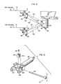
- the action of the mechanism coupling the rear housing 64 to the front housing 80 is best understood by reference to Fig. 4.
- the upper arm 100 and lower arm 102 form parallel links. There are two positions of the keyboard mounting plate 10 shown, namely, a high position and a low position. Because of the parallel links 100 and 102, and the pivotal connections provided by the pins 104, 112, 118, and 126, the tilt of the keyboard mounting plate 10 remains constant for all vertical positions of the front housing 80. This action occurs because the upper arm 100 and lower arm 102 form constant radii governing the arcuate movement of the pins 118 and 126 coupled to the front housing 80, pivoting about centers determined by the pins 104 and 112 in the rear housing 64.
- the rear housing 64 pivots preferably 360° about the axis 60 (this is the axis of the same-numbered stud in Fig. 5).
- the rear housing 64 is free to pivot about an axis which is generally perpendicular to the slide plate 50.
- the slide plate 50 may be moved to its rearward-most position, and the rear housing 64 pivoted to the extent necessary to pivot the entire keyboard support plate assembly underneath the work surface.
- the pivotal movement of the front housing 80 provides for pivotal movement of the front housing about an axis which is parallel to that of the pivotal movement of the rear housing 64.
- This pivotal movement of the front housing 80 is for the purpose of pivoting the keyboard mounting plate 10 to any desired position in use. Normally, only 90° of a pivoting movement of the front housing is required, and for this reason the stop pin 90 is included, as described above (with respect to Fig. 3).
- the two angular pivoting movements of the front and rear housings, together with the forward/backward movement of the slide plate 50 provide the necessary movement of the keyboard mounting plate 10 to provide any positioning of that plate desired by a computer operator.
- the gas cylinder mechanism participates in the movement of the keyboard mounting plate 10 by providing for the raising and lowering of the front housing 80.
- a gas cylinder activating rod 160 is included that passes through a hole 162 in the bracket 138.
- the activating rod 160 is fastened to a cam 164 by means of a set screw 166. Movement of the activating rod 160 moves the cam 164, which includes a dished surface 164a thereon that bears against activating button 132a of the gas cylinder. Appropriate movement of the activating rod 160 results in actuation of the gas cylinder activating button, in turn permitting the piston in the gas--cylinder to move.
- activation of the gas cylinder 132 results in the raising of the mounting plate by outward movement of the piston in the gas cylinder.
- the gas cylinder is activated by appropriate manipulation of the activating rod 160, and manual force is used to lower the keyboard mounting plate 10 to the desired position.
Landscapes
- Engineering & Computer Science (AREA)
- General Engineering & Computer Science (AREA)
- Mechanical Engineering (AREA)
- Input From Keyboards Or The Like (AREA)
Applications Claiming Priority (4)
| Application Number | Priority Date | Filing Date | Title |
|---|---|---|---|
| US49480983A | 1983-05-16 | 1983-05-16 | |
| US49481083A | 1983-05-16 | 1983-05-16 | |
| US494809 | 1983-05-16 | ||
| US494810 | 1983-05-16 |
Related Child Applications (2)
| Application Number | Title | Priority Date | Filing Date |
|---|---|---|---|
| EP90100892 Division | 1984-05-12 | ||
| EP90100892.0 Division-Into | 1984-05-12 |
Publications (2)
| Publication Number | Publication Date |
|---|---|
| EP0125669A2 true EP0125669A2 (de) | 1984-11-21 |
| EP0125669A3 EP0125669A3 (de) | 1986-06-04 |
Family
ID=27051550
Family Applications (1)
| Application Number | Title | Priority Date | Filing Date |
|---|---|---|---|
| EP84105396A Withdrawn EP0125669A3 (de) | 1983-05-16 | 1984-05-12 | Universalaufstellung eines Tastenfeldes und verstellbarer Tastenfeldträger |
Country Status (2)
| Country | Link |
|---|---|
| EP (1) | EP0125669A3 (de) |
| AU (2) | AU579819B2 (de) |
Cited By (3)
| Publication number | Priority date | Publication date | Assignee | Title |
|---|---|---|---|---|
| EP0244566A3 (en) * | 1986-04-19 | 1988-05-04 | International Business Machines Corporation | Support apparatus |
| EP0268802A1 (de) * | 1986-10-17 | 1988-06-01 | Wang Laboratories Inc. | Trägerarm für Computertastatur |
| EP0243945A3 (de) * | 1986-04-30 | 1989-10-11 | Günther Krüger | Vorrichtung zum Aufnehmen eines Datensichtgerätes und einer mit diesem verbundenen Tastatur |
Families Citing this family (1)
| Publication number | Priority date | Publication date | Assignee | Title |
|---|---|---|---|---|
| US5924664A (en) | 1997-03-12 | 1999-07-20 | Ergo View Technologies Corp. | Keyboard support mechanism |
Family Cites Families (1)
| Publication number | Priority date | Publication date | Assignee | Title |
|---|---|---|---|---|
| SE7802559L (sv) * | 1978-01-13 | 1979-07-14 | Moon Holdings Ltd C A | Justerbar veggkonsol |
-
1984
- 1984-05-12 EP EP84105396A patent/EP0125669A3/de not_active Withdrawn
- 1984-05-16 AU AU28074/84A patent/AU579819B2/en not_active Ceased
-
1989
- 1989-03-14 AU AU31285/89A patent/AU3128589A/en not_active Abandoned
Cited By (3)
| Publication number | Priority date | Publication date | Assignee | Title |
|---|---|---|---|---|
| EP0244566A3 (en) * | 1986-04-19 | 1988-05-04 | International Business Machines Corporation | Support apparatus |
| EP0243945A3 (de) * | 1986-04-30 | 1989-10-11 | Günther Krüger | Vorrichtung zum Aufnehmen eines Datensichtgerätes und einer mit diesem verbundenen Tastatur |
| EP0268802A1 (de) * | 1986-10-17 | 1988-06-01 | Wang Laboratories Inc. | Trägerarm für Computertastatur |
Also Published As
| Publication number | Publication date |
|---|---|
| AU3128589A (en) | 1989-07-06 |
| AU579819B2 (en) | 1988-12-15 |
| EP0125669A3 (de) | 1986-06-04 |
| AU2807484A (en) | 1984-11-22 |
Similar Documents
| Publication | Publication Date | Title |
|---|---|---|
| US4826123A (en) | Adjustable keyboard support | |
| US4938441A (en) | Slide plate adjustment mechanism | |
| US5145136A (en) | Adjustable support mechanism for a keyboard platform | |
| US5257767A (en) | Adjustable support mechanism for a keyboard platform | |
| US5037054A (en) | Adjustable support mechanism for a keyboard platform | |
| US4516327A (en) | Touch signal probe | |
| US4183494A (en) | Swiveled leaf-spring undercarriage for rocking chair | |
| US5590934A (en) | Adjustable chair-armrest assembly | |
| US5655814A (en) | Adjustable chair-armrest assembly | |
| JP3961020B2 (ja) | 安全かみそり | |
| EP1057429B1 (de) | Synchronstuhl mit wippbarem Sitz und Rückenlehne | |
| US5419615A (en) | Chair with adjustable seat and backrest | |
| US4621786A (en) | Camera mount and photographers seat | |
| JP2645792B2 (ja) | 産業車両の座席装置 | |
| JPS58136313A (ja) | 座家具着座部分のための錠止可能な傾動装置 | |
| JPH04502679A (ja) | キーボードに取り付け可能な調節自在のクランプを備えたポインティングデバイス | |
| EP0125669A2 (de) | Universalaufstellung eines Tastenfeldes und verstellbarer Tastenfeldträger | |
| CA1304350C (en) | Scissor jack stand | |
| US6257538B1 (en) | Keyboard mounting mechanism | |
| JP3980060B2 (ja) | 安全かみそり | |
| PT99310A (pt) | Mecanismo para montagem de um assento de cadeira | |
| US5560682A (en) | Adjustment mechanism for a chair | |
| JPH0985668A (ja) | フローティング機構 | |
| JPH11224056A (ja) | ディスプレイの姿勢設定装置とこのディスプレイの姿勢設定装置を備えた情報端末機器 | |
| GB2261809A (en) | Buckle support for a seat belt |
Legal Events
| Date | Code | Title | Description |
|---|---|---|---|
| PUAI | Public reference made under article 153(3) epc to a published international application that has entered the european phase |
Free format text: ORIGINAL CODE: 0009012 |
|
| AK | Designated contracting states |
Designated state(s): AT BE CH DE FR GB IT LI NL |
|
| PUAL | Search report despatched |
Free format text: ORIGINAL CODE: 0009013 |
|
| AK | Designated contracting states |
Kind code of ref document: A3 Designated state(s): AT BE CH DE FR GB IT LI NL |
|
| 17P | Request for examination filed |
Effective date: 19861030 |
|
| 17Q | First examination report despatched |
Effective date: 19880425 |
|
| STAA | Information on the status of an ep patent application or granted ep patent |
Free format text: STATUS: THE APPLICATION IS DEEMED TO BE WITHDRAWN |
|
| 18D | Application deemed to be withdrawn |
Effective date: 19900824 |
|
| RIN1 | Information on inventor provided before grant (corrected) |
Inventor name: WILMOT, GEORGE Inventor name: STEPHENS, WILLIAM I. Inventor name: SMITH, HAROLD A. Inventor name: CAMPBELL, PHILIP J. Inventor name: ARMSTRONG, ERIC C. Inventor name: HANNAH, BRUCE R. Inventor name: ELDON, JAMES B. |