EP0268802A1 - Trägerarm für Computertastatur - Google Patents
Trägerarm für Computertastatur Download PDFInfo
- Publication number
- EP0268802A1 EP0268802A1 EP87114951A EP87114951A EP0268802A1 EP 0268802 A1 EP0268802 A1 EP 0268802A1 EP 87114951 A EP87114951 A EP 87114951A EP 87114951 A EP87114951 A EP 87114951A EP 0268802 A1 EP0268802 A1 EP 0268802A1
- Authority
- EP
- European Patent Office
- Prior art keywords
- keyboard
- support arm
- desk
- arm
- base
- Prior art date
- Legal status (The legal status is an assumption and is not a legal conclusion. Google has not performed a legal analysis and makes no representation as to the accuracy of the status listed.)
- Granted
Links
Images

Classifications
-
- F—MECHANICAL ENGINEERING; LIGHTING; HEATING; WEAPONS; BLASTING
- F16—ENGINEERING ELEMENTS AND UNITS; GENERAL MEASURES FOR PRODUCING AND MAINTAINING EFFECTIVE FUNCTIONING OF MACHINES OR INSTALLATIONS; THERMAL INSULATION IN GENERAL
- F16M—FRAMES, CASINGS OR BEDS OF ENGINES, MACHINES OR APPARATUS, NOT SPECIFIC TO ENGINES, MACHINES OR APPARATUS PROVIDED FOR ELSEWHERE; STANDS; SUPPORTS
- F16M13/00—Other supports for positioning apparatus or articles; Means for steadying hand-held apparatus or articles
-
- A—HUMAN NECESSITIES
- A47—FURNITURE; DOMESTIC ARTICLES OR APPLIANCES; COFFEE MILLS; SPICE MILLS; SUCTION CLEANERS IN GENERAL
- A47B—TABLES; DESKS; OFFICE FURNITURE; CABINETS; DRAWERS; GENERAL DETAILS OF FURNITURE
- A47B21/00—Tables or desks for office equipment, e.g. typewriters, keyboards
- A47B21/03—Tables or desks for office equipment, e.g. typewriters, keyboards with substantially horizontally extensible or adjustable parts other than drawers, e.g. leaves
- A47B21/0314—Platforms for supporting office equipment
-
- F—MECHANICAL ENGINEERING; LIGHTING; HEATING; WEAPONS; BLASTING
- F16—ENGINEERING ELEMENTS AND UNITS; GENERAL MEASURES FOR PRODUCING AND MAINTAINING EFFECTIVE FUNCTIONING OF MACHINES OR INSTALLATIONS; THERMAL INSULATION IN GENERAL
- F16M—FRAMES, CASINGS OR BEDS OF ENGINES, MACHINES OR APPARATUS, NOT SPECIFIC TO ENGINES, MACHINES OR APPARATUS PROVIDED FOR ELSEWHERE; STANDS; SUPPORTS
- F16M11/00—Stands or trestles as supports for apparatus or articles placed thereon ; Stands for scientific apparatus such as gravitational force meters
- F16M11/02—Heads
- F16M11/04—Means for attachment of apparatus; Means allowing adjustment of the apparatus relatively to the stand
- F16M11/06—Means for attachment of apparatus; Means allowing adjustment of the apparatus relatively to the stand allowing pivoting
- F16M11/10—Means for attachment of apparatus; Means allowing adjustment of the apparatus relatively to the stand allowing pivoting around a horizontal axis
-
- F—MECHANICAL ENGINEERING; LIGHTING; HEATING; WEAPONS; BLASTING
- F16—ENGINEERING ELEMENTS AND UNITS; GENERAL MEASURES FOR PRODUCING AND MAINTAINING EFFECTIVE FUNCTIONING OF MACHINES OR INSTALLATIONS; THERMAL INSULATION IN GENERAL
- F16M—FRAMES, CASINGS OR BEDS OF ENGINES, MACHINES OR APPARATUS, NOT SPECIFIC TO ENGINES, MACHINES OR APPARATUS PROVIDED FOR ELSEWHERE; STANDS; SUPPORTS
- F16M11/00—Stands or trestles as supports for apparatus or articles placed thereon ; Stands for scientific apparatus such as gravitational force meters
- F16M11/20—Undercarriages with or without wheels
- F16M11/2007—Undercarriages with or without wheels comprising means allowing pivoting adjustment
- F16M11/2035—Undercarriages with or without wheels comprising means allowing pivoting adjustment in more than one direction
- F16M11/2064—Undercarriages with or without wheels comprising means allowing pivoting adjustment in more than one direction for tilting and panning
-
- A—HUMAN NECESSITIES
- A47—FURNITURE; DOMESTIC ARTICLES OR APPLIANCES; COFFEE MILLS; SPICE MILLS; SUCTION CLEANERS IN GENERAL
- A47B—TABLES; DESKS; OFFICE FURNITURE; CABINETS; DRAWERS; GENERAL DETAILS OF FURNITURE
- A47B21/00—Tables or desks for office equipment, e.g. typewriters, keyboards
- A47B21/03—Tables or desks for office equipment, e.g. typewriters, keyboards with substantially horizontally extensible or adjustable parts other than drawers, e.g. leaves
- A47B21/0314—Platforms for supporting office equipment
- A47B2021/0321—Keyboard supports
-
- A—HUMAN NECESSITIES
- A47—FURNITURE; DOMESTIC ARTICLES OR APPLIANCES; COFFEE MILLS; SPICE MILLS; SUCTION CLEANERS IN GENERAL
- A47B—TABLES; DESKS; OFFICE FURNITURE; CABINETS; DRAWERS; GENERAL DETAILS OF FURNITURE
- A47B21/00—Tables or desks for office equipment, e.g. typewriters, keyboards
- A47B21/03—Tables or desks for office equipment, e.g. typewriters, keyboards with substantially horizontally extensible or adjustable parts other than drawers, e.g. leaves
- A47B21/0314—Platforms for supporting office equipment
- A47B2021/0321—Keyboard supports
- A47B2021/0335—Keyboard supports mounted under the worksurface
-
- A—HUMAN NECESSITIES
- A47—FURNITURE; DOMESTIC ARTICLES OR APPLIANCES; COFFEE MILLS; SPICE MILLS; SUCTION CLEANERS IN GENERAL
- A47B—TABLES; DESKS; OFFICE FURNITURE; CABINETS; DRAWERS; GENERAL DETAILS OF FURNITURE
- A47B21/00—Tables or desks for office equipment, e.g. typewriters, keyboards
- A47B21/03—Tables or desks for office equipment, e.g. typewriters, keyboards with substantially horizontally extensible or adjustable parts other than drawers, e.g. leaves
- A47B21/0314—Platforms for supporting office equipment
- A47B2021/0321—Keyboard supports
- A47B2021/0335—Keyboard supports mounted under the worksurface
- A47B2021/0342—Keyboard supports mounted under the worksurface having one double articulated arm
-
- A—HUMAN NECESSITIES
- A47—FURNITURE; DOMESTIC ARTICLES OR APPLIANCES; COFFEE MILLS; SPICE MILLS; SUCTION CLEANERS IN GENERAL
- A47B—TABLES; DESKS; OFFICE FURNITURE; CABINETS; DRAWERS; GENERAL DETAILS OF FURNITURE
- A47B2200/00—General construction of tables or desks
- A47B2200/0084—Accessories for tables or desks
- A47B2200/0085—Supplementary support fixed on the edge of a desk or table
Definitions
- This invention relates to computer keyboards, and particularly to apparatus and furniture on which they are supported.
- Computer keyboards have become commonplace in the office environment. They are typically detached from the computer monitor and processing unit, and placed on top of the user's desk. In that location they permanently occupy valuable desk space, are at an ergonomically less desirable height, and typically lack any tilt adjustment. Some efforts have been made to improve the ergonomic positioning of the keyboard; e.g., special shelves have been built into computer work stations to lower the keyboard to a height below that of the customary desk surface.
- a computer keyboard can be supported at an ergonomically correct height during use and stored out of the way beneath an ordinary desk when not in use by supporting the keyboard on an arm that pivots about a base clamped to the edge of the desk.
- a joint with two degrees of freedom is provided at the keyboard end of the arm, to provide further ergonomic adjustment of the arm.
- the invention frees desktop space for more productive use and improves the appearance of the desk by allowing the keyboard to be stored out of sight. Supported on the arm, the keyboard moves easily and quickly from the stored position beneath the desk to the operating position, and vice versa. A wide range of adjustment is provided in the operating position; the keyboard can be tilted to the most comfortable position, and it can be rotated about the free end of the arm to achieve nearly any relative orientation with the desk.
- the arm provides a rigid platform for the keyboard even though supported from the desk at only a single location the rigidity is provided without the complexity of a special shelf or special computer workstation furniture. The arm can be attached rapidly without special tools to nearly all desks and tables, and it can easily be removed or moved to another location.
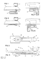
- a desk 10 to which are attached a computer video monitor 12 supported on arm 14 and a keyboard 16 supported on arm assembly 18.
- the keyboard can be moved from an operating position (Fig. 1) to a stored position beneath the desk (Fig. 2).
- the keyboard arm assembly 18 comprises base 20, which is clamped to the edge of the desk 10, horizontal arm 24 (die cast aluminum) rotatably supported from the base, and keyboard support plate 22 rotatably supported on the free end of the arm.
- Arm 24 has a hollow core through which the keyboard cable 26 is passed.
- the cable enters the arm through opening 28 in access panel 30, a polycarbonate sheet held in place by lugs gripping the interior walls of the arm's hollow core.
- the cable exits through an opening at the base end of the hollow core. Passing the cable through the arm minimizes movement of the cable during keyboard movements.
- the pivoting base 20 shown in cross section in Fig. 5, comprises a central member 32 (die case aluminum) to which arm 24 is rotatably connected at journal 34, which has bushing 36 (660 bronze, not oiled). Retention ring 38 secures arm 24 to the central member 32.
- Base 20 is attached to desk 10 by clamping the edge of the desk between adjustable clamping member 44 (die case aluminum) and the upper, knurled surface 42 of the central member.
- the clamping member 44 is adjusted by turning knob 46, which in turn rotates threaded rod 48 (steel), to which the clamping member is threaded.
- the desk-contact surface of clamping member 44 is provided with a rubber or cork pad (not shown) to prevent damages to the desk.
- the rod is press fitted into knob 46 (die case aluminum), and passes through bore 50 in central member 32.
- Knob 46 has rubber grip 47 at its periphery.
- Central member 32 has a cutout 70 sized to receive the vertical, cylindrical wall 72 of clamping member 44.
- Base portion 74 of the clamping member, through which rod 48 is threaded, is received by recess 76 in the central member.
- Retaining ring 78 prevents the whole assembly of rod 48, clamping member 44, and knob 46 from shifting vertically within the central member when the base is not installed on a desk.
- the shapes of clamping member 44 and central member 32 and length of rod 48 allow adjustment of the clamping member to accommodate desk thicknesses ranging from about 1.9 to 5.1 cm.
- Thrust washer 52 bears the upward thrust load of threaded rod 48 and knob 46 on the central member when the base is tightly clamped to the desk. No restraint on the freedom of rotation of arm 24 results from the clamping procedure, because knob 46 is prevented from coming into contact with the arm, by thrust washer 52 and the provision of adequate clearance 54 between the two parts. Arm 24 is free to pivot a full 360 degrees about a vertical axis of rotation.
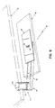
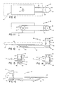
- Keyboard support plate 22 (molded structural foam) has base 56 with cylindrical surface 58, which mates with matching cylindrical surface 60 on intermediate member 62 (injection molded acetal), which rotates, in turn, on bearing surface 64 at the end of arm 24.
- Member 62 has a horizontal bearing surface provided by narrow annular projection 66, which contacts horizontal bearing surface 64 on the arm just inside annular lip 68.
- Bolt 80 clamps the three members (base 56, intermediate member 62, and arm 24) together.
- the head 82 of the bolt travels in slot 84 in keyboard support plate 22 (Figs. 3 and 6).
- the slot prescribes the extent to which the keyboard can be tilted.
- the keyboard can be quickly tilted or rotated into a new position, and retain that position without further adjustment. This is accomplished by using dissimilar plastics for base 56 and member 62, one material being hard, and the other slippery.
- the members making up the joint are tightened by nut 86 (with self-locking insert) and bolt 80 just tightly enough to assure that there is enough friction between base 56, intermediate member 62, and bearing surface 64 to keep the keyboard in its selected orientation.
- the nut is not adjusted so tightly, however, as to prevent adjustment of the relative positions of these members.
- the keyboard can be tilted about a horizontal axis of rotation from 15 degrees forward to 5 degrees backward, and it can be rotated about a vertical axis of rotation a full 360 degrees.
- Figs. 7 and 8 it can be seen that the ability of the keyboard to be rotated a full 360 degrees with respect to arm 24, an the arm, in turn, to be rotated a full 360 degrees with respect to the base, is what permits the keyboard to be positioned at any chosen angular orientation with respect to the desk, no matter whether installed at the left or right of the user.
- the arm assembly is installed on a desk by turning knob 46 to open the clamp to the desk thickness, pushing the clamp over the edge of the desk, and tightening knob 46 until the clamp is secured to the desk.
- the keyboard is then installed on the support plate 22 by screws passing through holes (not shown) in the support plate.
- An adhesively-secured adaptor plate could be used to install keyboards not having attachment screws in the proper locations.
- an optional surface for resting the user's palms in front of the keyboard can be provided by sandwiching a palm-rest plate between the keyboard and support plate 22, with the palm-rest plate extending outward in front of the keyboard.
- protruding pins could be substituted for the knurled desk-gripping surface of the clamp, to provide a more secure grip to the underside of the desk.
Landscapes
- Engineering & Computer Science (AREA)
- General Engineering & Computer Science (AREA)
- Mechanical Engineering (AREA)
- Input From Keyboards Or The Like (AREA)
Applications Claiming Priority (2)
| Application Number | Priority Date | Filing Date | Title |
|---|---|---|---|
| US92005086A | 1986-10-17 | 1986-10-17 | |
| US920050 | 1986-10-17 |
Publications (2)
| Publication Number | Publication Date |
|---|---|
| EP0268802A1 true EP0268802A1 (de) | 1988-06-01 |
| EP0268802B1 EP0268802B1 (de) | 1991-04-03 |
Family
ID=25443078
Family Applications (1)
| Application Number | Title | Priority Date | Filing Date |
|---|---|---|---|
| EP87114951A Expired - Lifetime EP0268802B1 (de) | 1986-10-17 | 1987-10-13 | Trägerarm für Computertastatur |
Country Status (5)
| Country | Link |
|---|---|
| EP (1) | EP0268802B1 (de) |
| JP (1) | JP2566255B2 (de) |
| AU (1) | AU598571B2 (de) |
| CA (1) | CA1275996C (de) |
| DE (1) | DE3769090D1 (de) |
Cited By (7)
| Publication number | Priority date | Publication date | Assignee | Title |
|---|---|---|---|---|
| US5403082A (en) * | 1992-06-19 | 1995-04-04 | Synsor Corporation | Fold-up, movable desk with movable audiovisual equipment end portion |
| FR2739267A1 (fr) * | 1995-08-24 | 1997-04-04 | Behavior Tech Computer Corp | Ensemble de support reglable pour clavier |
| WO1999000036A1 (en) * | 1997-06-26 | 1999-01-07 | Formway Furniture Limited | A work station support and/or a mounting bracket used in said work station support |
| US5931103A (en) * | 1997-05-21 | 1999-08-03 | Huang; Huei Mien | Computer desk |
| WO1999043233A1 (en) * | 1998-02-27 | 1999-09-02 | Shim, Jae, Chul | Arm supporting apparatus for users of computer mouse |
| US5974985A (en) * | 1994-10-20 | 1999-11-02 | Flototto Einrichtungssysteme Gmbh & Co. Kg | Table |
| US6220182B1 (en) | 1999-04-29 | 2001-04-24 | Moore North America, Inc. | Postal workstation |
Families Citing this family (1)
| Publication number | Priority date | Publication date | Assignee | Title |
|---|---|---|---|---|
| DE9109880U1 (de) * | 1991-08-09 | 1991-09-19 | Richard Tritsch GmbH Möbelfabrik, 7502 Malsch | Schreibtisch für Büros, Besprechungszimmer, Chefzimmer o.dgl. |
Citations (6)
| Publication number | Priority date | Publication date | Assignee | Title |
|---|---|---|---|---|
| DE2717289B2 (de) * | 1977-04-19 | 1979-12-13 | Hansa-Technik Gmbh, 2000 Hamburg | Schraubzwinge |
| EP0125669A2 (de) * | 1983-05-16 | 1984-11-21 | Knoll International, Inc. | Universalaufstellung eines Tastenfeldes und verstellbarer Tastenfeldträger |
| US4511276A (en) * | 1983-05-04 | 1985-04-16 | Doutt Kingsley A | Cylinder piston rod coupler |
| DE8507138U1 (de) * | 1985-03-12 | 1985-07-04 | Oeinck, Hans-Jürgen, Dipl.-Ing., 4400 Münster | Computer-Rolltisch |
| EP0168158A2 (de) * | 1984-06-08 | 1986-01-15 | Hauserman Inc. | Tisch |
| US4605334A (en) * | 1982-11-17 | 1986-08-12 | Ari Associates, Inc. | Linkage mechanism for coupling two movable members |
-
1987
- 1987-08-05 CA CA000543760A patent/CA1275996C/en not_active Expired - Lifetime
- 1987-08-11 AU AU76785/87A patent/AU598571B2/en not_active Ceased
- 1987-10-13 EP EP87114951A patent/EP0268802B1/de not_active Expired - Lifetime
- 1987-10-13 JP JP62258186A patent/JP2566255B2/ja not_active Expired - Lifetime
- 1987-10-13 DE DE8787114951T patent/DE3769090D1/de not_active Expired - Lifetime
Patent Citations (6)
| Publication number | Priority date | Publication date | Assignee | Title |
|---|---|---|---|---|
| DE2717289B2 (de) * | 1977-04-19 | 1979-12-13 | Hansa-Technik Gmbh, 2000 Hamburg | Schraubzwinge |
| US4605334A (en) * | 1982-11-17 | 1986-08-12 | Ari Associates, Inc. | Linkage mechanism for coupling two movable members |
| US4511276A (en) * | 1983-05-04 | 1985-04-16 | Doutt Kingsley A | Cylinder piston rod coupler |
| EP0125669A2 (de) * | 1983-05-16 | 1984-11-21 | Knoll International, Inc. | Universalaufstellung eines Tastenfeldes und verstellbarer Tastenfeldträger |
| EP0168158A2 (de) * | 1984-06-08 | 1986-01-15 | Hauserman Inc. | Tisch |
| DE8507138U1 (de) * | 1985-03-12 | 1985-07-04 | Oeinck, Hans-Jürgen, Dipl.-Ing., 4400 Münster | Computer-Rolltisch |
Cited By (11)
| Publication number | Priority date | Publication date | Assignee | Title |
|---|---|---|---|---|
| US5403082A (en) * | 1992-06-19 | 1995-04-04 | Synsor Corporation | Fold-up, movable desk with movable audiovisual equipment end portion |
| US5974985A (en) * | 1994-10-20 | 1999-11-02 | Flototto Einrichtungssysteme Gmbh & Co. Kg | Table |
| FR2739267A1 (fr) * | 1995-08-24 | 1997-04-04 | Behavior Tech Computer Corp | Ensemble de support reglable pour clavier |
| US5931103A (en) * | 1997-05-21 | 1999-08-03 | Huang; Huei Mien | Computer desk |
| WO1999000036A1 (en) * | 1997-06-26 | 1999-01-07 | Formway Furniture Limited | A work station support and/or a mounting bracket used in said work station support |
| GB2340747A (en) * | 1997-06-26 | 2000-03-01 | Formway Furniture Ltd | A work station support and/or a mounting bracket used in said work station support |
| GB2340747B (en) * | 1997-06-26 | 2001-07-25 | Formway Furniture Ltd | A work station support and/or a mounting bracket used in said work station support |
| US6289826B1 (en) | 1997-06-26 | 2001-09-18 | Formway Furniture Limited | Work station support and/or a mounting bracket used in said work station support |
| AU745076B2 (en) * | 1997-06-26 | 2002-03-14 | Formway Furniture Limited | A work station support and/or a mounting bracket used in said work station support |
| WO1999043233A1 (en) * | 1998-02-27 | 1999-09-02 | Shim, Jae, Chul | Arm supporting apparatus for users of computer mouse |
| US6220182B1 (en) | 1999-04-29 | 2001-04-24 | Moore North America, Inc. | Postal workstation |
Also Published As
| Publication number | Publication date |
|---|---|
| DE3769090D1 (de) | 1991-05-08 |
| CA1275996C (en) | 1990-11-06 |
| JP2566255B2 (ja) | 1996-12-25 |
| EP0268802B1 (de) | 1991-04-03 |
| AU7678587A (en) | 1988-04-21 |
| JPS63111517A (ja) | 1988-05-16 |
| AU598571B2 (en) | 1990-06-28 |
Similar Documents
| Publication | Publication Date | Title |
|---|---|---|
| US4844388A (en) | Support arm for computer keyboard | |
| EP0184353B1 (de) | Tragevorrichtung für Rechneranlage | |
| US5073050A (en) | Ergonomic keyboard apparatus | |
| US4863124A (en) | Corner work center | |
| US5832840A (en) | Tilt adjustable mouse surface mounting bracket | |
| US5577806A (en) | Adjustable footrest | |
| US4717112A (en) | Computer workstation | |
| US5636822A (en) | Computer mouse support | |
| US5230289A (en) | Keyboard support assembly | |
| US6298794B1 (en) | Ergonomic computer workstation | |
| US4688862A (en) | Workstation for electronic equipment operator | |
| US6422646B1 (en) | Keyboard support | |
| AU597850B2 (en) | Adjustable desk top assembly | |
| US6374752B1 (en) | Ergonomic computer workstation | |
| US5791259A (en) | Adjustable shelf support assembly computer work station | |
| US8371237B2 (en) | Computer work station with moveable monitor support | |
| US5483898A (en) | Tilting and sliding surface assembly for a table | |
| US20060278770A1 (en) | AirDesk free standing and vehicle mounted 6-axis positionable tray, positionable shelf, cup-holder, stanchion apparatus and related systems | |
| CA2121344A1 (en) | Adjustable keyboard holder for computer workstation | |
| US12460767B2 (en) | Arm assembly | |
| US20090301360A1 (en) | Keyboard and mouse support | |
| US6604786B1 (en) | Support apparatus for a chair | |
| EP0268802B1 (de) | Trägerarm für Computertastatur | |
| US20030042373A1 (en) | Ergonomic positioning apparatus for computers and or computer accessories | |
| US5667320A (en) | Keyboard, palm rest, and, mouse tray positioning system |
Legal Events
| Date | Code | Title | Description |
|---|---|---|---|
| PUAI | Public reference made under article 153(3) epc to a published international application that has entered the european phase |
Free format text: ORIGINAL CODE: 0009012 |
|
| AK | Designated contracting states |
Kind code of ref document: A1 Designated state(s): BE DE FR GB |
|
| 17P | Request for examination filed |
Effective date: 19881020 |
|
| 17Q | First examination report despatched |
Effective date: 19900105 |
|
| GRAA | (expected) grant |
Free format text: ORIGINAL CODE: 0009210 |
|
| AK | Designated contracting states |
Kind code of ref document: B1 Designated state(s): BE DE FR GB |
|
| REF | Corresponds to: |
Ref document number: 3769090 Country of ref document: DE Date of ref document: 19910508 |
|
| ET | Fr: translation filed | ||
| PLBE | No opposition filed within time limit |
Free format text: ORIGINAL CODE: 0009261 |
|
| STAA | Information on the status of an ep patent application or granted ep patent |
Free format text: STATUS: NO OPPOSITION FILED WITHIN TIME LIMIT |
|
| 26N | No opposition filed | ||
| PGFP | Annual fee paid to national office [announced via postgrant information from national office to epo] |
Ref country code: FR Payment date: 19950913 Year of fee payment: 9 |
|
| PGFP | Annual fee paid to national office [announced via postgrant information from national office to epo] |
Ref country code: DE Payment date: 19950925 Year of fee payment: 9 Ref country code: BE Payment date: 19950925 Year of fee payment: 9 |
|
| PGFP | Annual fee paid to national office [announced via postgrant information from national office to epo] |
Ref country code: GB Payment date: 19950927 Year of fee payment: 9 |
|
| PG25 | Lapsed in a contracting state [announced via postgrant information from national office to epo] |
Ref country code: GB Effective date: 19961013 |
|
| PG25 | Lapsed in a contracting state [announced via postgrant information from national office to epo] |
Ref country code: BE Effective date: 19961031 |
|
| BERE | Be: lapsed |
Owner name: WANG LABORATORIES INC. Effective date: 19961031 |
|
| GBPC | Gb: european patent ceased through non-payment of renewal fee |
Effective date: 19961013 |
|
| PG25 | Lapsed in a contracting state [announced via postgrant information from national office to epo] |
Ref country code: FR Effective date: 19970630 |
|
| PG25 | Lapsed in a contracting state [announced via postgrant information from national office to epo] |
Ref country code: DE Effective date: 19970701 |
|
| REG | Reference to a national code |
Ref country code: FR Ref legal event code: ST |