EP0125857A2 - Teilchenzähler - Google Patents
Teilchenzähler Download PDFInfo
- Publication number
- EP0125857A2 EP0125857A2 EP84303053A EP84303053A EP0125857A2 EP 0125857 A2 EP0125857 A2 EP 0125857A2 EP 84303053 A EP84303053 A EP 84303053A EP 84303053 A EP84303053 A EP 84303053A EP 0125857 A2 EP0125857 A2 EP 0125857A2
- Authority
- EP
- European Patent Office
- Prior art keywords
- solution
- sample solution
- sheath
- syringe pump
- pipe
- Prior art date
- Legal status (The legal status is an assumption and is not a legal conclusion. Google has not performed a legal analysis and makes no representation as to the accuracy of the status listed.)
- Granted
Links
- 239000012488 sample solution Substances 0.000 claims abstract description 102
- 239000000243 solution Substances 0.000 claims abstract description 63
- 210000004027 cell Anatomy 0.000 claims abstract description 33
- 210000000601 blood cell Anatomy 0.000 claims abstract description 30
- XLYOFNOQVPJJNP-UHFFFAOYSA-N water Substances O XLYOFNOQVPJJNP-UHFFFAOYSA-N 0.000 claims abstract description 25
- 210000004369 blood Anatomy 0.000 claims abstract description 19
- 239000008280 blood Substances 0.000 claims abstract description 19
- 239000002504 physiological saline solution Substances 0.000 claims abstract description 6
- 238000004140 cleaning Methods 0.000 claims description 25
- 239000007788 liquid Substances 0.000 claims description 21
- 238000004891 communication Methods 0.000 claims description 14
- 230000003287 optical effect Effects 0.000 claims description 10
- 230000000694 effects Effects 0.000 claims description 4
- 230000002441 reversible effect Effects 0.000 abstract description 10
- 238000001514 detection method Methods 0.000 description 5
- 239000006193 liquid solution Substances 0.000 description 5
- 238000005259 measurement Methods 0.000 description 4
- 238000010276 construction Methods 0.000 description 3
- 238000000034 method Methods 0.000 description 3
- 238000007599 discharging Methods 0.000 description 2
- 230000005540 biological transmission Effects 0.000 description 1
- 230000007423 decrease Effects 0.000 description 1
- 238000007865 diluting Methods 0.000 description 1
- 239000000428 dust Substances 0.000 description 1
- -1 for example Substances 0.000 description 1
- 239000011521 glass Substances 0.000 description 1
- 239000012535 impurity Substances 0.000 description 1
- 238000003780 insertion Methods 0.000 description 1
- 230000037431 insertion Effects 0.000 description 1
- 239000000463 material Substances 0.000 description 1
- 230000002093 peripheral effect Effects 0.000 description 1
- 102000004169 proteins and genes Human genes 0.000 description 1
- 108090000623 proteins and genes Proteins 0.000 description 1
- 239000000523 sample Substances 0.000 description 1
- 230000035945 sensitivity Effects 0.000 description 1
Images


Classifications
-
- G—PHYSICS
- G01—MEASURING; TESTING
- G01N—INVESTIGATING OR ANALYSING MATERIALS BY DETERMINING THEIR CHEMICAL OR PHYSICAL PROPERTIES
- G01N15/00—Investigating characteristics of particles; Investigating permeability, pore-volume or surface-area of porous materials
- G01N15/10—Investigating individual particles
- G01N15/14—Optical investigation techniques, e.g. flow cytometry
- G01N15/1404—Handling flow, e.g. hydrodynamic focusing
-
- G—PHYSICS
- G01—MEASURING; TESTING
- G01N—INVESTIGATING OR ANALYSING MATERIALS BY DETERMINING THEIR CHEMICAL OR PHYSICAL PROPERTIES
- G01N21/00—Investigating or analysing materials by the use of optical means, i.e. using sub-millimetre waves, infrared, visible or ultraviolet light
- G01N21/01—Arrangements or apparatus for facilitating the optical investigation
- G01N21/11—Filling or emptying of cuvettes
Definitions
- the present invention relates to a grain counter such as, for example, a blood corpuscle counter for measuring the size of a blood corpuscle and the number of blood corpuscles, thereby examing the blood and, more particularly, to a grain counter which makes it possible to obtain a fine, stable blood column.
- a grain counter such as, for example, a blood corpuscle counter for measuring the size of a blood corpuscle and the number of blood corpuscles, thereby examing the blood and, more particularly, to a grain counter which makes it possible to obtain a fine, stable blood column.
- a blood corpuscle counter in order to increase the measuring precision, it is necessary to cause diluted blood to flow into a pipe having a small inner diameter and make the region to be measured by a sensor small.
- blood to be measured sometimes contains dust, which is introduced when it is extracted, or coagulated components. When such blood is allowed to flow through the fine pipe, the interior of the pipe is blocked. This is one of the drawbacks inherent in this type of blood corpuscle counter.
- a water sheath technique has been proposed for eliminating this drawback.
- Fig. 1 a type view showing the water sheath principle is shown.
- a flow cell 10 has an outer tube 12 and an inner tube 14, for example, concentrically disposed in the outer tube 12.
- a sample solution 18 such as, for example, diluted blood is allowed to flow through the inner tube 14 in a direction indicated by a solid line.
- a sheath solution 16 such as, for example, physiological saline solution is allowed to flow through the interspace between the outer tube 12 and the inner tube 14 in a direction indicated by a broken line.
- two flows of solution consisting respectively of a solution column of sample solution 18 and the sheath solution enclosing this solution column, are created.
- the diameter of the two-flow unit consisting of the sheath solution 16 and the sample solution 18 is reduced, whereby a water sheath is formed wherein a fine flow of sample solution 18 is sheathed by the sheath solution 16.
- the inner diameter of the inner tube 14 through which the sample solution is allowed to flow can be made large enough to prevent the interior of the inner tube from being blocked by the sample solution 18.
- this small-diameter portion can not be blocked by the sample solution 18 since the sheath solution 16 exists around the column of sample solution.
- the water sheath is formed with the use of the device shown in Fig. 2.
- the outer tube 12 is connected to a closed talk or reservoir 20 by means of a pipe 22.
- the inner tube 14 is connected to a closed reservoir 24 by means of a pipe 26,
- the reservoirs 20 and 24 are connected to a compressed air supply source by means of pipes 28 and 30, respectively so that compressed air may be supplied to the reservoirs 20 and 24, respectively.
- the sheath solution 16 and sample solution 18 are supplied to the outer tube 12 and the inner tube 14 through the pipes 22 and 26, respectively.
- the object of the present invention is to provide a simply constructed grain counter which is capable of reducing the cross sectional column of sample solution of the water sheath to a stable and constant diameter and thereby measure the size and number of grains with high precision.
- a grain counter so arranged as to form a water sheath consisting of two flows of solution, consisting respectively of a flow of sample solution and a flow of sheath solution existing around the flow of sample solution, thereby sensing the state of the grains contained in the flow of sample solution.
- This grain counter comprises: a sample solution receptacle for storing a sample solution therein; a sheath solution receptacle for storing a sheath solution therein, a flow cell having an inner tube connected to the sample solution receptacle and an outer tube connected to the sheath solution, whereby to form a flow of sheath solution, supplied to the outer tube, around a flow of sample solution, supplied to the inner tube, thereby to form a water sheath consisting of such two flows of solution; and a measuring means for sensing the state of the grains contained in the flow of sample solution.
- a first syringe pump has a first plunger, the movement of which causes the sample solution to be sucked from the sample solution receptacle and this sample solution to be supplied into the inner tube of the flow cell.
- a second syringe pump has a second plunger, the movement of which causes the sheath solution to be sucked from the sheath solution receptacle and this sheath solution to be fed into the outer tube of the flow cell.
- a connecting member connects the first plunger and second plunger, said connecting member being moved by a drive means, whereby the first and second plungers are moved at the same speed.
- the present invention can provide a stable water sheath since the plungers supply sheath solution and sample solution directly to the flow cell at a constant speed. Since both plungers are mechanically connected, they are moved at the same speed and in the same direction. With a simple construction, therefore, the cross sectional flow of sample solution of the water sheath can be reduced to a specified and stable diameter without using a complicated controlling means. For this reason, the grain counter according to the present invention makes it possible to measure the state of grains such as the size, number, etc. thereof with high precision.
- the flow of sample solution can not be blocked during the process of its measurement. Further, since the grains flow or pass through a specified position of the flow cell, no variation in sensitivity occurs during the sensing step, due to the variation in position of passing of the grains, whereby it is possible to make measurement of the grain with high precision. Further, according to the present invention, since the diameter of the flow of sample solution can be reduced to prevent two or more grains (blood corpuscle) from existing in the area of measurement, it is possible to precisely measure the number of the grains.
- a flow cell 40 is made of a material such as glass which is capable of transmitting a light therethrough. It is constructed in the same manner as that in which a flow cell 10 (see Fig. l) is constructed, and has an outer tube 42 and an inner tube 44.
- a sample solution 84 i.e., diluted blood.
- a sheath solution 88 that is, a dilute solution such as, for example, physiological saline solution.
- the receptacle 82 is connected to the inner tube 44 of the flow cell 40 through a pipe 92 and a pipe 104 while, on the other hand, the receptacle 86 is connected to the outer tube 42 of the flow cell 40 through a pipe 94 and a pipe 106. Tip ends of the pipes 92 and 94 are immersed in the sample solution 84 and the sheath solution 88 in the receptacles 82 and 86, respectively. Three-way valves 100 and 102 are disposed between the pipes 92 and 104 and between the pipes 94 and 106, respectively.
- Syringe pumps 72 and 76 are connected to the three-way valves 100 and 102, respectively, through a pipe 96 and a pipe 98.
- Each pipe 92, 94, 96, 98, 104 or 106 is for example 2mm in inner diameter.
- the pipes 96 and 98 in particular are respectively long enough to store therein a sample solution for the examination of blood and a sheath solution.
- the syringe pumps 72 and 76 are, for example, 1 mm and 10 mm in inner diameter, respectively.
- the volume (inner cross sectional area) of the syringe pump 76 is approximately one hundred times as great as that of the syringe pump 72.
- a reversible motor 62 is provided on the outer surface of the fixing plate 56 in such a manner that its rotation shaft is extended through an insertion bore 56a provided in the fixing plate 56 and protruded therefrom toward the support plate 52.
- a screw rod 60 is fixed with its axis being in alignment with that rotation shaft, said screw rod being formed with an external thread on its outer peripheral surface.
- the screw rod 60 is screwed into a threaded bore 58a formed in the connecting plate 58.
- the plungers 74 and 78 are moved, in a state wherein they are interlocked, at the same speed (for example, 1.25 mm/sec) in the direction indicated by the arrow 4.
- the sample solution and sheath solution in the syringe pumps 72 and 76 are allowed to flow through the pipes 96 and 104 and the pipes 98 and 106, respectively, to be fed into the flow cell 40.
- two flows of solution consisting respectively of a solution column of sample solution and a sheath solution existing around the column of sample solution, are thus formed from the sample solution and sheath solution fed thereinto.
- This two-flow unit consisting of the sheath solution and the sample solution is reduced in cross section by the small-diameter portion 46 of the outer tube 42, whereby a water sheath is formed.
- the sample solution thus reaches, in the form of such a water sheath, the measuring means 110 after passing through the small-diameter portion 46.
- the radius r of the sample solution reduced in cross section to form a water sheath can be expressed by the formula (1) below.
- Sf represents the cross sectional area of the small-diameter portion 46 of the flow cell 40
- Ss the cross sectional area of the plunger 78 for feeding the sheath solution
- Sb the cross sectional area of the plunger 74 for feeding the sample solution (the cross sectional area of the interior of the syringe pump 72). Since the cross sectional area of the interior of the syringe pump 76 is much greater than that of the syringe pump 72 (Ss » Sb), the folllowing formula (2) holds true.
- the flow of the sample solution existing at the small-diameter portion 46 becomes approximately 22 ⁇ m in diameter. This means that the flow of sample solution has a reduced diameter which permits one blood corpuscle to flow through.
- the laser beams emitted from the laser beam emission means 112 are irradiated onto the flow of sample solution in the small-diameter portion 46 after being focussed or condensed by the optical lens means 114.
- the laser beams pass straight through such an irradiated spot and are intercepted by the beam stopper 116. Accordingly, it is impossible that those laser beams are sensed by the optical sensor means or beam sensor 124.
- any blood corpuscle exists in said irradiated spot part of the laser beams is scattered by that blood corpuscle. Of the laser beams thus scattered, a part not intercepted by the beam stopper 116 is condensed by the lens 118. Of these laser beams, a part having passed through the slit 120 is sensed by the beam sensor 124.
- This specified relation is such that as the size of a blood corpuscle increases, the intensity of the scattered beams increases.
- a sample solution prepared by diluting blood to a concentration several hundreds of times lower than the original concentration of the blood it is possible that no blood corpuscle at all exists in the flow of such a sample solution allowed to flow through the laser-beam irradiated spot or area of the small-diameter portion 46.
- the frequency at which the intensity of the scattered beam sensed by the beam sensor increases it is possible to know the number of blood corpuscles involved.
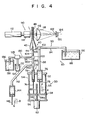
- FIG. 4 The blood corpuscle counter according to a second embodiment of the invention will now be described with reference to Fig. 4.
- This second embodiment is so arranged as to prevent blood from being left in the pipes, so as to effectively utilize the blood.
- Fig. 4 the same members and portions or sections as those shown in Fig. 3 are denoted by same reference numerals and their descriptions are omitted.
- a pipe 130 in place of the pipe 92 is connected to the three-way valve 100.
- the pipe 130 is introduced into the sample solution 134 stored in a receptacle 132.
- a cleaning liquid 138 such as, for example, a physiological saline solution, which is similar to the sheath solution 88, is received in a receptacle 136.
- a tip end portion of the pipe 130 can also be immersed into the cleaning liquid 138 in the receptacle 136.
- a switching means selectively switches the pipe 130 to one of the receptacles 132, 136 from the other for effecting the communication between both.
- a three-way valve 140 is mounted between a pipe portion 96a and a pipe portion 96b of the pipe 96. To the three-way valve 140 is connected a pipe 142, to which is connected a large capacity syringe pump 144 having an inner diameter of, for example, 10 mm. A plunger 146 of the syringe pump 144 can be reciprocally moved in directions 6 and 8 to permit the matter in the syringe pump 144 to be either discharged from or sucked into the syringe pump.
- the operation of the blood corpuscle counter having the above-mentioned construction will now be described.
- the three-way valves 100, 102 and 104 are mounted at positions connecting the pipes 96 and 130, the pipes 94 and 98, and the pipe portions 96a and 96b, respectively.
- the pipe 130 is immersed in the sample solution 134 received or stored in the receptacle 132.
- the reversible motor 62 is driven to rotate.
- the connecting plate 58 is moved in the direction indicated by the arrow 2 by the resultant rotation of the screw rod or externally threaded rod 60 kept in screw engagement with the threaded bore 58a.
- the plungers 74 and 78 are moved in the direction in which they are withdrawn from the syringe pumps 72 and 76, respectively.
- the sample solution 134 and the sheath solution 88 in the receptacles 132 and 86 are sucked into the syringe pumps 72 and 76, respectively.
- a specified amount (which corresponds to a pipe length of, for example, two or three centimeters) of the sample solution is sucked into the pipes 96a and 130, the rotation of the reversible motor 62 is stopped.
- the tip end of the pipe 130 is immersed into the cleaning liquid solution 138 in the receptacle 136 by the switching means 128.
- the three-way valve 140 is so switched as to connect the pipe 96a and the pipe 142, and then the plunger 146 is moved in the direction indicated by the arrow 6.
- the movement of this plunger can be made by rotation of a motor, as in the case of the plungers 74 and 78.
- the cleaning liquid solution 138 in the receptacle 136 is sucked into the pipe 130.
- the movement of the plunger 146 is stopped.
- the three-way valve 100 is so switched as to connect the pipe 104 and the pipe portion 96a.
- a motor used to drive the plunger 146, is rotated in the reverse direction, thereby to move the plunger 146 in the direction indicated by the arrow 8.
- the cleaning liquid and the sample solution in the pipes 96a and 142 flow through the pipe 104 and are thus supplied into the flow cell 40.
- the sample solution and cleaning solution are not mixed together and flow toward the flow cell 40 in a state wherein the sample solution immediately follows the cleaning liquid. Accordingly, since the interiors of the pipe 104 and inner tube 44 are washed by the forward cleaning liquid, it is impossible that the sample solution is contaminated by a sample solution used in the preceding examination.
- the plunger 146 is stopped from being moved. Subsequently, the three-way valve 140 is switched so as to allow the communication of the pipe portion 96a with the pipe portion 96b, while on the other hand, the three-way valve 102 is switched so as to allow the communication of the pipe 98 with the pipe 106.
- the reversible motor 62 is rotated, causing the screw rod 60 to rotate about its axis and the connecting plate 58a moves in the direction indicated by the arrow 4.
- the sample solution 134 is fed into the inner tube 44 of the flow cell 40, and the sheath solution 88 is fed into the outer tube 42.
- a water sheath is formed with respeto the sample solution.
- the size and the number of blood corpuscles in the flow of the diluted blood, as water-sheathed, are measured by the measuring means 110 in the same procedure as in the preceding embodiment of Fig. 3.
- the second embodiment also has the effect of avoiding the useless consumption of a sample solution, or blood. That is to say, in the embodiment of Fig. 3, of the sample solution sucked into the pipes 92 and 96, the part left in the pipe 92 when the three-way valve 100 is switched to allow the communication between the pipes 96 and 104 is thrown away. In the embodiment of Fig. 4, however, the sample solution sucked out of the receptacle 132 is wholly fed into the flow cell 40 and used for measurement of the blood corpuscles contained therein.
- the sample solution 134 is sucked and discharged by the syringe pump 72, while the cleaning liquid 138 is sucked and discharged by the syringe pump 144 with a capacity larger than that of the syringe pump 72. Accordingly, where the sample solution is fed, it is possible to keep a precise feeding rate at a constant value because of the long moving distance of the plunger. And where the cleaning liquid is fed, it is possible to suck and discharge it at high rate. According to this second embodiment, therefore, it is possible to measure the blood corpuscles quickly with high precision.
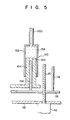
- the blood corpuscle counter according to a third embodiment of the invention will now be described with reference to Fig. 5.
- the syringe pump 72 and the syring pump 144 are made into an integral pump unit.
- the third embodiment is the same as the embodiment of Fig. 4, except that in Fig. 5 a syringe pump 150 is provided in place of the syringe pump 72 and that the three-way valve 140, pipe 142, syringe pump 144, and plunger 146 are not provided.
- the syringe pump 150 has a large-diameter cylinder 152 connected to the pipe portion 96b, a large-diameter piston 154, and a small-diameter piston 156.
- the piston 154 is inserted into a hollow portion 158 of the cylinder 152.
- the piston 154 is made substantially cylindrical, and the piston 156 is inserted into a hollow portion 160 of the piston 154.
- the piston 156 has its one end fixed on the connecting plate 58 and is moved interlockingly with the plunger 78.
- the piston 154 is connected to another moving means, whereby it can be moved separately from, or independently of, the piston 156.
- the sample solution in the receptacle 132 is sucked by the movement of the piston 156, resulting from the movement of the connecting plate 58, while the cleaning liquid solution 138 in the receptacle 136 is sucked by moving the piston 154 via another moving means.
- the blood corpuscles can be examined quickly with high precision as in the case of the preceding embodiment shown in Fig. 4.
Landscapes
- Chemical & Material Sciences (AREA)
- Dispersion Chemistry (AREA)
- Physics & Mathematics (AREA)
- Health & Medical Sciences (AREA)
- Life Sciences & Earth Sciences (AREA)
- Analytical Chemistry (AREA)
- Biochemistry (AREA)
- General Health & Medical Sciences (AREA)
- General Physics & Mathematics (AREA)
- Immunology (AREA)
- Pathology (AREA)
- Investigating Or Analysing Biological Materials (AREA)
Applications Claiming Priority (4)
| Application Number | Priority Date | Filing Date | Title |
|---|---|---|---|
| JP83422/83 | 1983-05-12 | ||
| JP8342283A JPS59208438A (ja) | 1983-05-12 | 1983-05-12 | 血球計測装置 |
| JP8342383A JPS59208439A (ja) | 1983-05-12 | 1983-05-12 | 粒子カウンタ |
| JP83423/83 | 1983-05-12 |
Publications (3)
| Publication Number | Publication Date |
|---|---|
| EP0125857A2 true EP0125857A2 (de) | 1984-11-21 |
| EP0125857A3 EP0125857A3 (en) | 1986-02-26 |
| EP0125857B1 EP0125857B1 (de) | 1989-04-26 |
Family
ID=26424447
Family Applications (1)
| Application Number | Title | Priority Date | Filing Date |
|---|---|---|---|
| EP84303053A Expired EP0125857B1 (de) | 1983-05-12 | 1984-05-04 | Teilchenzähler |
Country Status (3)
| Country | Link |
|---|---|
| US (1) | US4606631A (de) |
| EP (1) | EP0125857B1 (de) |
| DE (1) | DE3477966D1 (de) |
Cited By (3)
| Publication number | Priority date | Publication date | Assignee | Title |
|---|---|---|---|---|
| EP0286088A3 (en) * | 1987-04-08 | 1990-05-30 | Hitachi, Ltd. | A sheath flow type flow-cell device |
| EP0317809A3 (de) * | 1987-11-25 | 1990-08-29 | Becton, Dickinson and Company | Vorrichtung für umhüllten Teilchendurchfluss mit Kontrolle durch Differentialdruck |
| US6251615B1 (en) | 1998-02-20 | 2001-06-26 | Cell Analytics, Inc. | Cell analysis methods |
Families Citing this family (22)
| Publication number | Priority date | Publication date | Assignee | Title |
|---|---|---|---|---|
| US4850707A (en) * | 1986-06-06 | 1989-07-25 | Massachusetts Institute Of Technology | Optical pulse particle size analyzer |
| JPS63307332A (ja) * | 1987-06-08 | 1988-12-15 | Hitachi Ltd | 光計測式生体細胞分析装置 |
| US5245318A (en) * | 1987-07-24 | 1993-09-14 | Canon Kabushiki Kaisha | Particle analyzing apparatus having pressure control system |
| US5134445A (en) * | 1989-02-14 | 1992-07-28 | Canon Kabushiki Kaisha | Sample inspecting method and apparatus |
| JPH0353164A (ja) * | 1989-07-20 | 1991-03-07 | Canon Inc | サンプル供給装置及びこれを用いたサンプル測定装置 |
| US5249029A (en) * | 1989-09-02 | 1993-09-28 | Bayer Aktiengesellschaft | Apparatus for determining the size distribution of pigment particles in a paint surface |
| US5293219A (en) * | 1991-12-31 | 1994-03-08 | Andritz Sprout-Bauer, Inc. | Fiber length analyzer |
| US5397539A (en) * | 1992-04-23 | 1995-03-14 | Toray Industries, Inc. | Automatic analyzing apparatus |
| US6812032B1 (en) | 1993-01-21 | 2004-11-02 | Cdc Technologies, Inc. | Apparatus and method for making a plurality of reagent mixtures and analyzing particle distributions of the reagent mixtures |
| US5439750A (en) * | 1993-06-15 | 1995-08-08 | General Electric Company | Titanium metal matrix composite inserts for stiffening turbine engine components |
| DE69434965D1 (de) * | 1994-09-06 | 2007-06-14 | Cdc Technologies Inc | Vorrichtung zum pumpen und führen von flüssigkeiten im zusammenhang mit hämatologischen prüfungen |
| US5649576A (en) * | 1996-02-26 | 1997-07-22 | Pharmacopeia, Inc. | Partitioning device |
| BR9816214B1 (pt) * | 1997-11-28 | 2009-01-13 | dispositivo e processo de medida da velocidade de desaglomeraÇço por ultra-som de uma carga que se apresenta sob a forma de aglomerados de partÍculas. | |
| FR2803660B1 (fr) * | 2000-01-07 | 2002-04-05 | Cetim Sa | Dispositif d'analyse spectrophotometrique de fluides |
| US7079242B2 (en) * | 2003-12-19 | 2006-07-18 | Core Laboratories L.P. | Method and apparatus for determining characteristics of particles in a fluid sample |
| US20050151968A1 (en) * | 2004-01-08 | 2005-07-14 | The Lxt Group | Systems and methods for continuous, on-line, real-time surveillance of particles in a fluid |
| JP5162177B2 (ja) * | 2007-07-31 | 2013-03-13 | シスメックス株式会社 | 粒子分析装置及び粒子分析方法 |
| WO2013188770A1 (en) * | 2012-06-14 | 2013-12-19 | Bio-Rad Laboratories, Inc. | Flow rate balanced, dynamically adjustable sheath delivery system for flow cytometry |
| ES2711364T3 (es) * | 2013-03-15 | 2019-05-03 | Iris Int Inc | Sistemas y métodos de célula de flujo para el análisis de partículas en muestras de sangre |
| WO2019041270A1 (zh) * | 2017-08-31 | 2019-03-07 | 深圳迈瑞生物医疗电子股份有限公司 | 样本检测装置、样本分析仪及样本检测方法 |
| US11327007B2 (en) * | 2019-09-26 | 2022-05-10 | Fluidsens International Inc. | Compact and secure system and method for detecting particles in fluid |
| WO2022225597A1 (en) * | 2021-04-23 | 2022-10-27 | Becton, Dickinson And Company | Fluid management system for an analyzer and/or sorter type flow type particle analyzer |
Family Cites Families (11)
| Publication number | Priority date | Publication date | Assignee | Title |
|---|---|---|---|---|
| US3661460A (en) * | 1970-08-28 | 1972-05-09 | Technicon Instr | Method and apparatus for optical analysis of the contents of a sheathed stream |
| US3790760A (en) * | 1971-09-27 | 1974-02-05 | Cornell Aeronautical Labor Inc | Apparatus for counting, differentiating and sorting particles according to their microstructure variations |
| US3845309A (en) * | 1973-09-10 | 1974-10-29 | Thermo Electron Corp | Fluorescent gas analyzer |
| NL7500390A (en) * | 1975-01-13 | 1976-07-15 | Consiglio Nazionale Ricerche | Injection of liquids into mixer for physico-chemical analysis - for chemical physical analysis using electromagnets to control syringes |
| US4129381A (en) * | 1976-10-28 | 1978-12-12 | Miles Laboratories, Inc. | Apparatus and method for preparing a particle suspension |
| US4178103A (en) * | 1977-03-28 | 1979-12-11 | Chromatix, Inc. | Light scattering photometer and sample handling system therefor |
| US4367043A (en) * | 1980-05-05 | 1983-01-04 | Leland Stanford Junior University | Method and means for delivering liquid samples to a sample scanning device |
| FR2484077B1 (fr) * | 1980-06-06 | 1984-07-06 | Inst Nat Sante Rech Med | Procede et dispositif de mesure de la deformabilite de cellules vivantes, notamment des globules rouges du sang |
| JPS5886463A (ja) * | 1981-11-19 | 1983-05-24 | Olympus Optical Co Ltd | 分注装置 |
| US4510438A (en) * | 1982-02-16 | 1985-04-09 | Coulter Electronics, Inc. | Coincidence correction in particle analysis system |
| US4683212A (en) * | 1982-09-30 | 1987-07-28 | Technicon Instruments Corporation | Random access single channel sheath stream apparatus |
-
1984
- 1984-05-04 DE DE8484303053T patent/DE3477966D1/de not_active Expired
- 1984-05-04 US US06/607,311 patent/US4606631A/en not_active Expired - Fee Related
- 1984-05-04 EP EP84303053A patent/EP0125857B1/de not_active Expired
Cited By (4)
| Publication number | Priority date | Publication date | Assignee | Title |
|---|---|---|---|---|
| EP0286088A3 (en) * | 1987-04-08 | 1990-05-30 | Hitachi, Ltd. | A sheath flow type flow-cell device |
| US4983038A (en) * | 1987-04-08 | 1991-01-08 | Hitachi, Ltd. | Sheath flow type flow-cell device |
| EP0317809A3 (de) * | 1987-11-25 | 1990-08-29 | Becton, Dickinson and Company | Vorrichtung für umhüllten Teilchendurchfluss mit Kontrolle durch Differentialdruck |
| US6251615B1 (en) | 1998-02-20 | 2001-06-26 | Cell Analytics, Inc. | Cell analysis methods |
Also Published As
| Publication number | Publication date |
|---|---|
| DE3477966D1 (en) | 1989-06-01 |
| US4606631A (en) | 1986-08-19 |
| EP0125857B1 (de) | 1989-04-26 |
| EP0125857A3 (en) | 1986-02-26 |
Similar Documents
| Publication | Publication Date | Title |
|---|---|---|
| EP0125857B1 (de) | Teilchenzähler | |
| EP0619476B1 (de) | Vorrichtung zur Detektion einer Flüssigkeitphasengrenze in einem lichtdurchlässigen Messrohr | |
| US9494507B2 (en) | Apparatus and method to determine the blood sedimentation rate and other parameters connected thereto | |
| DE102007003040B4 (de) | Vorrichtung zur optischen Detektion eines Phasenübergangs oder dergleichen | |
| EP0038912B1 (de) | Sensorkanüle | |
| EP2299253B1 (de) | Probenidentifizierungs- und verteilungsvorrichtung sowie probenidentifizierungs- und verteilungsverfahren | |
| JP4897978B2 (ja) | 検体の解析装置及び検体の解析方法 | |
| US5552885A (en) | Measuring chamber for flow cytometer | |
| EP0614077A2 (de) | Durchflusszellenvorrichtung | |
| CA1196836A (en) | Random access single channel sheath stream apparatus | |
| US8136539B2 (en) | Wash ring assembly and method of use | |
| EP3839476A1 (de) | Vorrichtung und verfahren zur bestimmung einer position und/oder einer ausdehnung eines tropfens | |
| DE60223684T2 (de) | Einrichtung zur laserinduzierten fluoreszenzanalyse und trennvorrichtung damit | |
| EP0553276A4 (de) | ||
| JPH06194299A (ja) | フローセル装置 | |
| US20190145998A1 (en) | Device And Method To Sample Liquids With High-Precision In An Automated Sample Analyzer | |
| JPH0436636A (ja) | フローセル装置 | |
| US20070041875A1 (en) | Flow analysis dispensing needles and nozzles | |
| EP0101161B1 (de) | Verfahren und Vorrichtung zur gleichzeitigen Förderung zweier Flüssigkeiten durch eine Analysenzelle | |
| JP5075540B2 (ja) | 分注方法、自動分析装置の試料分注方法、および自動分析装置 | |
| JP4352147B2 (ja) | 液体定量供給用具 | |
| JPS5915835A (ja) | 透光性毛細管を用いた定量希釈方法および定量希釈装置 | |
| CA2183639C (en) | Method for sucking/determining liquid and pipetting device driven and controlled according to method | |
| JPH0471184B2 (de) | ||
| WO2016117042A1 (ja) | 分析装置 |
Legal Events
| Date | Code | Title | Description |
|---|---|---|---|
| PUAI | Public reference made under article 153(3) epc to a published international application that has entered the european phase |
Free format text: ORIGINAL CODE: 0009012 |
|
| 17P | Request for examination filed |
Effective date: 19840521 |
|
| AK | Designated contracting states |
Designated state(s): DE FR GB |
|
| PUAL | Search report despatched |
Free format text: ORIGINAL CODE: 0009013 |
|
| AK | Designated contracting states |
Designated state(s): DE FR GB |
|
| 17Q | First examination report despatched |
Effective date: 19871007 |
|
| GRAA | (expected) grant |
Free format text: ORIGINAL CODE: 0009210 |
|
| AK | Designated contracting states |
Kind code of ref document: B1 Designated state(s): DE FR GB |
|
| PGFP | Annual fee paid to national office [announced via postgrant information from national office to epo] |
Ref country code: FR Payment date: 19890517 Year of fee payment: 6 |
|
| REF | Corresponds to: |
Ref document number: 3477966 Country of ref document: DE Date of ref document: 19890601 |
|
| EN | Fr: translation not filed | ||
| PLBE | No opposition filed within time limit |
Free format text: ORIGINAL CODE: 0009261 |
|
| STAA | Information on the status of an ep patent application or granted ep patent |
Free format text: STATUS: NO OPPOSITION FILED WITHIN TIME LIMIT |
|
| 26N | No opposition filed | ||
| REG | Reference to a national code |
Ref country code: GB Ref legal event code: 746 Effective date: 19981012 |
|
| PGFP | Annual fee paid to national office [announced via postgrant information from national office to epo] |
Ref country code: GB Payment date: 19990505 Year of fee payment: 16 |
|
| PGFP | Annual fee paid to national office [announced via postgrant information from national office to epo] |
Ref country code: DE Payment date: 19990507 Year of fee payment: 16 |
|
| PG25 | Lapsed in a contracting state [announced via postgrant information from national office to epo] |
Ref country code: GB Free format text: LAPSE BECAUSE OF NON-PAYMENT OF DUE FEES Effective date: 20000504 |
|
| GBPC | Gb: european patent ceased through non-payment of renewal fee |
Effective date: 20000504 |
|
| PG25 | Lapsed in a contracting state [announced via postgrant information from national office to epo] |
Ref country code: DE Free format text: LAPSE BECAUSE OF NON-PAYMENT OF DUE FEES Effective date: 20010301 |
|
| PG25 | Lapsed in a contracting state [announced via postgrant information from national office to epo] |
Ref country code: FR Free format text: LAPSE BECAUSE OF NON-PAYMENT OF DUE FEES Effective date: 19900531 |