EP0125860B1 - Moyens d'ancrage pour ceinture de sécurité - Google Patents
Moyens d'ancrage pour ceinture de sécurité Download PDFInfo
- Publication number
- EP0125860B1 EP0125860B1 EP84303065A EP84303065A EP0125860B1 EP 0125860 B1 EP0125860 B1 EP 0125860B1 EP 84303065 A EP84303065 A EP 84303065A EP 84303065 A EP84303065 A EP 84303065A EP 0125860 B1 EP0125860 B1 EP 0125860B1
- Authority
- EP
- European Patent Office
- Prior art keywords
- latch member
- formation
- traveller
- pushpad
- track
- Prior art date
- Legal status (The legal status is an assumption and is not a legal conclusion. Google has not performed a legal analysis and makes no representation as to the accuracy of the status listed.)
- Expired
Links
- 230000015572 biosynthetic process Effects 0.000 claims description 52
- 238000005755 formation reaction Methods 0.000 claims description 52
- 230000000903 blocking effect Effects 0.000 claims description 19
- 230000000295 complement effect Effects 0.000 claims description 15
- 230000001133 acceleration Effects 0.000 claims description 7
- 230000000994 depressogenic effect Effects 0.000 description 3
- 125000006850 spacer group Chemical group 0.000 description 3
- 230000006835 compression Effects 0.000 description 2
- 238000007906 compression Methods 0.000 description 2
- 238000010586 diagram Methods 0.000 description 2
- 229920003023 plastic Polymers 0.000 description 2
- 239000004033 plastic Substances 0.000 description 2
- 230000000694 effects Effects 0.000 description 1
- 230000002401 inhibitory effect Effects 0.000 description 1
- 238000003780 insertion Methods 0.000 description 1
- 230000037431 insertion Effects 0.000 description 1
- 230000003993 interaction Effects 0.000 description 1
- 239000002184 metal Substances 0.000 description 1
- 230000004048 modification Effects 0.000 description 1
- 238000012986 modification Methods 0.000 description 1
Images
Classifications
-
- B—PERFORMING OPERATIONS; TRANSPORTING
- B60—VEHICLES IN GENERAL
- B60R—VEHICLES, VEHICLE FITTINGS, OR VEHICLE PARTS, NOT OTHERWISE PROVIDED FOR
- B60R21/00—Arrangements or fittings on vehicles for protecting or preventing injuries to occupants or pedestrians in case of accidents or other traffic risks
- B60R21/02—Occupant safety arrangements or fittings, e.g. crash pads
- B60R21/16—Inflatable occupant restraints or confinements designed to inflate upon impact or impending impact, e.g. air bags
- B60R21/18—Inflatable occupant restraints or confinements designed to inflate upon impact or impending impact, e.g. air bags the inflatable member formed as a belt or harness or combined with a belt or harness arrangement
-
- B—PERFORMING OPERATIONS; TRANSPORTING
- B60—VEHICLES IN GENERAL
- B60R—VEHICLES, VEHICLE FITTINGS, OR VEHICLE PARTS, NOT OTHERWISE PROVIDED FOR
- B60R22/00—Safety belts or body harnesses in vehicles
- B60R22/18—Anchoring devices
- B60R22/20—Anchoring devices adjustable in position, e.g. in height
- B60R22/201—Anchoring devices adjustable in position, e.g. in height with the belt anchor connected to a slider movable in a vehicle-mounted track
- B60R22/202—Anchoring devices adjustable in position, e.g. in height with the belt anchor connected to a slider movable in a vehicle-mounted track the slider comprising spring-actuated locking means
- B60R22/203—Anchoring devices adjustable in position, e.g. in height with the belt anchor connected to a slider movable in a vehicle-mounted track the slider comprising spring-actuated locking means the locking means being movably mounted on the slider
-
- B—PERFORMING OPERATIONS; TRANSPORTING
- B60—VEHICLES IN GENERAL
- B60R—VEHICLES, VEHICLE FITTINGS, OR VEHICLE PARTS, NOT OTHERWISE PROVIDED FOR
- B60R21/00—Arrangements or fittings on vehicles for protecting or preventing injuries to occupants or pedestrians in case of accidents or other traffic risks
- B60R2021/0002—Type of accident
- B60R2021/0006—Lateral collision
Definitions
- This invention relates to anchorage r.,eans for vehicle safety belts and particularly to anchorage means of the kind which are adapted to be mounted on a vehicle body above the shoulder level of the occupant of an adjacent seat for reception of the shoulder strap of the safety belt.
- the present invention is particularly concerned with the provision of a shoulder anchorage of adjustable height.
- DE-A-2 947 391 discloses an adjustable shoulder anchorage assembly comprising a vertically extending track mounted on the interior of a vehicle body above the level of the shoulders of an occupant of an adjacent seat, a traveller mounted on the track, a latch member pivotally mounted on the traveller and carrying a latching formation for engagement with complementary formations on the track so as to inhibit movement of the traveller along the track, and a guide member having a slot for receiving the strap of a safety belt pivotally mounted on the latch member so that the guide member is angularly movable about a horizontal axis.
- the latching formation can be disengaged from the complementary formations on the track by pressing on the pivotal mounting means for the guide member.
- the total mass of the latch member, the guide member and the pivotal mounting of the latter is such that, in the event of the vehicle being subject to high lateral acceleration, for example as a result of impact during an accident, a substantial force tending to disengage the latching formation may be produced, with the re- sultthat the resilient biasing means has to be capable of exerting a substantially greater force.
- an adjustable shoulder anchorage assembly comprising a vertically extending track mounted on the interior of a vehicle body above the level of the shoulders of an occupant of an adjacent seat, a traveller mounted on the track, a guide member secured to the traveller and having a slot for receiving the strap of a safety belt, a latch member having a latching formation thereon, resilient means for biasing the latching formation into engagement with one of a series of complementary formations on the track so as to inhibit movement of the traveller along the track
- the assembly further comprises blocking means for preventing movement of the latching formation out of engagement with the complementary formations and manual release means operative first to inhibit the blocking means and then to disengage the latching formation from the complementary formations.
- the latch member is L-shaped and has an opening in one limb surrounding the pivotal mounting means and engaging with a shoulderthere- on, the other limb projecting beyond the track and carrying the latching formation and the resilient means being arranged to bias the first limb.
- the blocking means may comprise a member movable longitudinally in guides on the traveller between a position in which it engages under a projection on the latch member and a position in which it is clear of such projection, a cam formation on a pushpad being adapted to displace such member to the latter position.
- the blocking means may comprise a resilient strut projecting from the traveller generally in the direction of movement of the latch member and the pushpad, into engagement with the cam formation on the latter, such strut having a shoulder which engages under a corresponding shoulder on the latch member.
- the release means preferably comprises a pushpad which is resiliently biased away from the latch member in the same direction as the latch member is resiliently biased relative to the traveller and the pushpad carries a cam formation which disables the locking means when the pushpad is moved into abutment with the latch member. Further depression of the pushpad then causes a corresponding movement of the latch member resulting in disengagement of the latching formation from the complementary formations.
- the release means may be pivotally mounted on the traveller and the blocking means may comprise a blocking formation on the release means which is movable between a first position in which the blocking formation engages with a complementary formation on the latch member to inhibit movement of the latter from its first position, an intermediate position in which said blocking formation is disengaged from said complementary formation and an actuating formation engages with the latch member, and a third position in which said actuating formation has moved the latch member into its second position.
- the release means is pivotally mounted and balanced about its pivot point so as not to be susceptible to such lateral acceleration.
- the blocking formation and the complementary formation on the latch member may be so shaped that any tendency of the latch member to move towards its second position, when the manual release means is in its first position, resists movement of the manual release means towards its intermediate position.
- the blocking means inhibits accidental movement of the latch member to its released position due to inertia as a result of high lateral acceleration of the vehicle, for example due to impact.
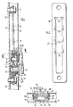
- the track 10 of an adjustable shoulder anchorage assembly in accordance with the invention is mounted on the B-post 12 by two bolts 14 and 16 and spacers 18 and 20.
- the track 10 has a central elongate slot 22 with four aligned pairs of notches 24, 26, 28 and 30 in its side edges.
- the pair of notches 24 is disposed at the top of the slot 22.
- the upper edges of the other three pairs of notches 26, 28 and 30 are pressed outwardly to form lead-in ramps 32 on the side of the track 10 facing the B-post 12.
- a traveller for movement along the track 10 comprises a base member 40 and a plastics body 42.
- the body 42 has a pocket 44 which projects through a hole in the base member 40 and accommodates a compression spring 46, the purpose of which will be explained hereinafter.
- the body 42 also includes a boss 50 which surrounds a metal spacer 52 surrounding a bolt 54 which is screwed into the base plate 40 and by which the slotted member 56 for receiving the seat belt strap is pivotally secured to the traveller.
- the boss 50 on the plastics body 42 has a shoulder 60 on its outer end.
- a L-shaped latch member 62 has the end of its longer limb widened to accommodate a hole which is snapped over the shoulder 60 prior to insertion of the spacer 52, after which the latch member 62 is held captive on the boss 50.
- the shorter limb of the latch member 62 projects through the slot 22 in the track 10 and into a slot in the base member 40 of the traveller.
- the shorter limb of the latch member 62 has a main portion 66 which is narrow enough to pass through the slot 22 at any position, a pair of shoulders 68 which can pass through the slot 22 only when in aligment with one of the pairs of notches 24, 26, 28, 30, and an end portion 70 which is too wide to pass through the slot 22 even when in alignment with one of the pairs of notches but which is narrower than the length of the slot 64 in the base plate 40.
- the spring 46 engages with the latch member 62 so as to bias it in the clockwise direction (as viewed in Figure 1) about the fulcrum provided by the shoulder 60, the end portion 70 engaging with the side of the track 10 nearer to the B-post 12 when the shoulders 68 are received in one of the pairs of notches 24, 26, 28 and 30.
- the base member 40 has outwardly facing side limbs 72 and 74 which contain elongate holes 76 through which the ends of a transverse rod 78 project.
- the latch 62 has a projection 80 which engages in front of the rod 78 when the latter is at the lower end of the slot 76.
- a pushpad 82 is pivotally mounted at 84 on the latch member 62 and has two side flanged 86 and 88 each of which has an oblique slot 90 through which the rod 78 projects.
- the pushpad 82 is biased by a leaf spring (not shown) away from the latch member 66. This leaf spring is much weaker than the spring 46 which biases the latch member 62 away from the base member 40.
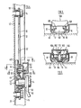
- Figures 4to 6 illustrate an alternative embodiment of the invention which has a different blocking means from that illustrated in Figures 1 to 3.
- Many of the components of the assembly are identical with the corresponding components of the assembly illustrated in Figures 1 to 3. These identical components are denoted by the same reference numerals and will not be described in detail.
- the latch member 100 illustrated in Figures 4 to 6 differs from the latch member 62 in that it does not have a projection 80. Instead, it has a T-shaped opening 102 aligned with the axis of the spring 46, the cross-bar of the T-shape extending transversely of the latch member 100 and the stem thereof projecting towards the boss 50.
- a resilient strut 104 extends through the centre of the spring 46. For most of its length, the width of the strut 104 is such that it can pass through the wider part of the opening 102 formed by the cross-bar of the T-shape but not through the narrower part formed by the stem thereof. However the strut 104 has a narrow end portion 106 which can pass through any part of the opening 102.
- the length of the broader part of the strut 104 is such that when the shoulder at the junction with the narrower part 106 engage with the edges of the narrower part of the opening 102, the latch member 100 is blocked from moving its engaged to its released position.
- the free end of the broader part of the strut 104 is secured to the bottom of the pocket 44 at such angle that the resilience of the strut 104 biases its other end towards the narrower end of the opening 102, thereby maintaining the latch member 100 in its blocked condition.
- the pushpad 82 of Figures 1 to 3 is replaced by a pushpad 108 having a cam formation 110 which engages with the free end of the narrower portion 106 of the strut 104 so that, on the one hand the resilience of the strut 104 urges the pushpad 108 away from the latch member 100 and, on the other hand, when the pushpad 108 is depressed, the cam formation 110 displaced the strut 104 away from the narrow part of the opening 102, thereby unblocking the latch member 100.
- the cam formation 110 bottoms on the latch member 100, further depression of the pushpad 108 disengages the latch member 100 so that the traveller 40 is free to slide along the track 10.
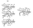
- Figures 7 to 10 illustrate a modification of the embodiment shown in Figures 1 to 3, having a latch member 120 which is held captive on the boss 50.
- the sliding pushpad 82 is replaced by a release lever 122 having stub axles 124 on each side which are journaled in bearings (not shown) formed on each side of the pocket 44 of the traveller.
- the lever 122 carries a manually accessible pushpad 126 and a segmental flange 128 which has a shoulder 130 on its radially outer edge.
- the latch member 120 has a projection 132 projecting parallel to the flange 128 in alignment with the shoulder 130.
- the interengaging faces of the projection 132 and the shoulder 130 are inclined so that the force exerted by the latch pivoting in the direction indicated by the arrow 136 would cause the release lever 122 to pivot in the direction indicated by the arrow 138 and thus be more firmly held in position.
- the release lever 122 is approximately balanced about its stub axles 124 that it is not itself affected by any such high acceleration.
Landscapes
- Engineering & Computer Science (AREA)
- Mechanical Engineering (AREA)
- Automotive Seat Belt Assembly (AREA)
Claims (9)
Applications Claiming Priority (4)
| Application Number | Priority Date | Filing Date | Title |
|---|---|---|---|
| GB838313023A GB8313023D0 (en) | 1983-05-11 | 1983-05-11 | Anchorage means for vehicle safety seats |
| GB8313023 | 1983-05-11 | ||
| GB838313622A GB8313622D0 (en) | 1983-05-17 | 1983-05-17 | Anchorage means |
| GB8313622 | 1983-05-17 |
Publications (3)
| Publication Number | Publication Date |
|---|---|
| EP0125860A1 EP0125860A1 (fr) | 1984-11-21 |
| EP0125860B1 true EP0125860B1 (fr) | 1986-08-27 |
| EP0125860B2 EP0125860B2 (fr) | 1992-04-29 |
Family
ID=26286091
Family Applications (1)
| Application Number | Title | Priority Date | Filing Date |
|---|---|---|---|
| EP84303065A Expired EP0125860B2 (fr) | 1983-05-11 | 1984-05-08 | Moyens d'ancrage pour ceinture de sécurité |
Country Status (6)
| Country | Link |
|---|---|
| EP (1) | EP0125860B2 (fr) |
| KR (1) | KR840009267A (fr) |
| AU (1) | AU561295B2 (fr) |
| DE (1) | DE3460551D1 (fr) |
| ES (1) | ES279226Y (fr) |
| MY (1) | MY8700472A (fr) |
Families Citing this family (4)
| Publication number | Priority date | Publication date | Assignee | Title |
|---|---|---|---|---|
| EP0187225A3 (fr) * | 1984-11-15 | 1987-12-16 | Autoflug GmbH & Co Fahrzeugtechnik | Dispositif de réglage de la hauteur pour une ferrure de fixation ou de renvoi |
| US4765651A (en) * | 1986-05-13 | 1988-08-23 | American Safety Equipment Corporation | Adjustable anchoring slide block assembly |
| US4940254A (en) * | 1987-05-28 | 1990-07-10 | Nissan Motor Co., Ltd. | Seat belt holder position adjuster |
| US7513531B2 (en) * | 2005-10-04 | 2009-04-07 | Takata Seat Belts, Inc. | Simplified height adjuster for D-ring |
Family Cites Families (4)
| Publication number | Priority date | Publication date | Assignee | Title |
|---|---|---|---|---|
| DE2932505C3 (de) * | 1979-08-10 | 1982-02-11 | Daimler-Benz Ag, 7000 Stuttgart | An einem Fahrzeughohlträger angeordnete Vorrichtung zur stufenweisen Höhenverstellung des Umlenkbeschlages eines Sicherheitsgurtsystems |
| DE2947391A1 (de) * | 1979-11-24 | 1981-05-27 | Volkswagenwerk Ag, 3180 Wolfsburg | Vorrichtung zur verstellung eines sicherheitsgurt-verankerungspunktes |
| DE3007986C2 (de) * | 1980-03-01 | 1983-09-15 | Bayerische Motoren Werke AG, 8000 München | Vorrichtung zum Verstellen eines karosseriefest angeordneten Gurtbeschlages |
| DE3030209A1 (de) * | 1980-08-09 | 1982-03-18 | Bayerische Motoren Werke AG, 8000 München | Vorrichtung zum hoehenverstellen eines umlenkbeschlages fuer den schultergurt |
-
1984
- 1984-05-04 KR KR1019840002426A patent/KR840009267A/ko not_active Ceased
- 1984-05-04 AU AU27698/84A patent/AU561295B2/en not_active Ceased
- 1984-05-08 DE DE8484303065T patent/DE3460551D1/de not_active Expired
- 1984-05-08 EP EP84303065A patent/EP0125860B2/fr not_active Expired
- 1984-05-09 ES ES1984279226U patent/ES279226Y/es not_active Expired
-
1987
- 1987-12-30 MY MY472/87A patent/MY8700472A/xx unknown
Also Published As
| Publication number | Publication date |
|---|---|
| ES279226U (es) | 1984-12-01 |
| KR840009267A (ko) | 1984-12-26 |
| AU561295B2 (en) | 1987-05-07 |
| AU2769884A (en) | 1984-11-15 |
| EP0125860A1 (fr) | 1984-11-21 |
| EP0125860B2 (fr) | 1992-04-29 |
| MY8700472A (en) | 1987-12-31 |
| DE3460551D1 (en) | 1986-10-02 |
| ES279226Y (es) | 1985-06-01 |
Similar Documents
| Publication | Publication Date | Title |
|---|---|---|
| US4569537A (en) | Anchorage means for vehicle safety belts | |
| US4545097A (en) | Lock for a safety belt | |
| US4872704A (en) | Device for height adjustment of a safety belt fitting | |
| US4197619A (en) | Tongue and buckle fastener for a safety belt harness | |
| US5163207A (en) | Shock proof buckle for safety belts | |
| SE8306258L (sv) | Hojdinstellningsanordning for ett fordonssekerhetsbelte | |
| US5366243A (en) | Height adjuster for seat belt shoulder strap | |
| USRE32524E (en) | Adjustable seat belt anchorage | |
| CZ280093B6 (cs) | Zařízení pro výškové nastavení kování bezpečnostního pásu | |
| US5341546A (en) | Seat belt buckle | |
| EP0125860B1 (fr) | Moyens d'ancrage pour ceinture de sécurité | |
| US3728764A (en) | Dual actuation safety belt buckle mechanism | |
| US4572544A (en) | Anchorage means for vehicle safety belts | |
| EP0147059A2 (fr) | Dispositif de serrage pour une courroie | |
| US5784766A (en) | Buckle mechanism | |
| US4310954A (en) | Buckle | |
| EP0173477A3 (fr) | Moyens d'ancrage pour ceintures de sécurité de véhicules | |
| US5542162A (en) | Buckle for safety belts | |
| US6170134B1 (en) | Seat belt buckle | |
| JPH0790748B2 (ja) | 安全ベルト取付具の垂直調節のための装置 | |
| EP0249910A1 (fr) | Dispositif d'ancrage réglable en hauteur pour une ferrure de renvoi | |
| US6202269B1 (en) | Seat belt buckle | |
| US6088890A (en) | Safety belt buckle | |
| KR19980070466A (ko) | 차량 안전 벨트 시스템의 편향을 맞추기 위한 조절 장치 | |
| US4848796A (en) | Device for adjusting the position of a strap return element of a vehicle safety belt |
Legal Events
| Date | Code | Title | Description |
|---|---|---|---|
| PUAI | Public reference made under article 153(3) epc to a published international application that has entered the european phase |
Free format text: ORIGINAL CODE: 0009012 |
|
| AK | Designated contracting states |
Designated state(s): DE FR GB IT SE |
|
| 17P | Request for examination filed |
Effective date: 19841115 |
|
| RBV | Designated contracting states (corrected) |
Designated state(s): DE FR GB IT |
|
| GRAA | (expected) grant |
Free format text: ORIGINAL CODE: 0009210 |
|
| AK | Designated contracting states |
Kind code of ref document: B1 Designated state(s): DE FR GB IT |
|
| REF | Corresponds to: |
Ref document number: 3460551 Country of ref document: DE Date of ref document: 19861002 |
|
| ET | Fr: translation filed | ||
| ITF | It: translation for a ep patent filed | ||
| RAP2 | Party data changed (patent owner data changed or rights of a patent transferred) |
Owner name: BRITAX WINGARD LIMITED |
|
| PLBI | Opposition filed |
Free format text: ORIGINAL CODE: 0009260 |
|
| 26 | Opposition filed |
Opponent name: AUTOFLUG GMBH & CO FAHRZEUGTECHNIK Effective date: 19870526 |
|
| PLAB | Opposition data, opponent's data or that of the opponent's representative modified |
Free format text: ORIGINAL CODE: 0009299OPPO |
|
| R26 | Opposition filed (corrected) |
Opponent name: AUTOFLUG GMBH & CO FAHRZEUGTECHNIK Effective date: 19870526 |
|
| RAP2 | Party data changed (patent owner data changed or rights of a patent transferred) |
Owner name: ELECTROLUX AUTOLIV AB |
|
| PGFP | Annual fee paid to national office [announced via postgrant information from national office to epo] |
Ref country code: FR Payment date: 19910522 Year of fee payment: 8 |
|
| ITTA | It: last paid annual fee | ||
| PUAH | Patent maintained in amended form |
Free format text: ORIGINAL CODE: 0009272 |
|
| STAA | Information on the status of an ep patent application or granted ep patent |
Free format text: STATUS: PATENT MAINTAINED AS AMENDED |
|
| 27A | Patent maintained in amended form |
Effective date: 19920429 |
|
| AK | Designated contracting states |
Kind code of ref document: B2 Designated state(s): DE FR GB IT |
|
| PG25 | Lapsed in a contracting state [announced via postgrant information from national office to epo] |
Ref country code: FR Effective date: 19930129 |
|
| REG | Reference to a national code |
Ref country code: FR Ref legal event code: ST |
|
| PGFP | Annual fee paid to national office [announced via postgrant information from national office to epo] |
Ref country code: GB Payment date: 19960429 Year of fee payment: 13 |
|
| PGFP | Annual fee paid to national office [announced via postgrant information from national office to epo] |
Ref country code: DE Payment date: 19960513 Year of fee payment: 13 |
|
| PG25 | Lapsed in a contracting state [announced via postgrant information from national office to epo] |
Ref country code: GB Effective date: 19970508 |
|
| GBPC | Gb: european patent ceased through non-payment of renewal fee |
Effective date: 19970508 |
|
| PG25 | Lapsed in a contracting state [announced via postgrant information from national office to epo] |
Ref country code: DE Free format text: LAPSE BECAUSE OF NON-PAYMENT OF DUE FEES Effective date: 19980203 |