EP0126051A2 - Verfahren und Anlage zum Verhüten des Schleuderns und des Gleitens zwischen antreibbaren und bremsbaren Rädern und der Stutzfläche in Kraftfahrzeugantriebssystemen - Google Patents
Verfahren und Anlage zum Verhüten des Schleuderns und des Gleitens zwischen antreibbaren und bremsbaren Rädern und der Stutzfläche in Kraftfahrzeugantriebssystemen Download PDFInfo
- Publication number
- EP0126051A2 EP0126051A2 EP84850147A EP84850147A EP0126051A2 EP 0126051 A2 EP0126051 A2 EP 0126051A2 EP 84850147 A EP84850147 A EP 84850147A EP 84850147 A EP84850147 A EP 84850147A EP 0126051 A2 EP0126051 A2 EP 0126051A2
- Authority
- EP
- European Patent Office
- Prior art keywords
- acceleration
- wheels
- wheel
- rotary speed
- skidding
- Prior art date
- Legal status (The legal status is an assumption and is not a legal conclusion. Google has not performed a legal analysis and makes no representation as to the accuracy of the status listed.)
- Granted
Links
- 238000000034 method Methods 0.000 title claims abstract description 20
- 230000001133 acceleration Effects 0.000 claims abstract description 52
- 230000001419 dependent effect Effects 0.000 claims abstract description 6
- 230000005540 biological transmission Effects 0.000 description 3
- 238000010586 diagram Methods 0.000 description 3
- 230000003137 locomotive effect Effects 0.000 description 3
- 230000008030 elimination Effects 0.000 description 2
- 238000003379 elimination reaction Methods 0.000 description 2
- 230000002706 hydrostatic effect Effects 0.000 description 2
- 230000009467 reduction Effects 0.000 description 2
- 238000012360 testing method Methods 0.000 description 2
- 230000008859 change Effects 0.000 description 1
- 238000002485 combustion reaction Methods 0.000 description 1
- 230000002596 correlated effect Effects 0.000 description 1
- 230000000875 corresponding effect Effects 0.000 description 1
- 238000013461 design Methods 0.000 description 1
- 238000012986 modification Methods 0.000 description 1
- 230000004048 modification Effects 0.000 description 1
- 230000002265 prevention Effects 0.000 description 1
- 230000008569 process Effects 0.000 description 1
- 238000012545 processing Methods 0.000 description 1
- 230000011664 signaling Effects 0.000 description 1
Images
Classifications
-
- B—PERFORMING OPERATIONS; TRANSPORTING
- B60—VEHICLES IN GENERAL
- B60T—VEHICLE BRAKE CONTROL SYSTEMS OR PARTS THEREOF; BRAKE CONTROL SYSTEMS OR PARTS THEREOF, IN GENERAL; ARRANGEMENT OF BRAKING ELEMENTS ON VEHICLES IN GENERAL; PORTABLE DEVICES FOR PREVENTING UNWANTED MOVEMENT OF VEHICLES; VEHICLE MODIFICATIONS TO FACILITATE COOLING OF BRAKES
- B60T8/00—Arrangements for adjusting wheel-braking force to meet varying vehicular or ground-surface conditions, e.g. limiting or varying distribution of braking force
- B60T8/17—Using electrical or electronic regulation means to control braking
- B60T8/175—Brake regulation specially adapted to prevent excessive wheel spin during vehicle acceleration, e.g. for traction control
-
- B—PERFORMING OPERATIONS; TRANSPORTING
- B60—VEHICLES IN GENERAL
- B60T—VEHICLE BRAKE CONTROL SYSTEMS OR PARTS THEREOF; BRAKE CONTROL SYSTEMS OR PARTS THEREOF, IN GENERAL; ARRANGEMENT OF BRAKING ELEMENTS ON VEHICLES IN GENERAL; PORTABLE DEVICES FOR PREVENTING UNWANTED MOVEMENT OF VEHICLES; VEHICLE MODIFICATIONS TO FACILITATE COOLING OF BRAKES
- B60T8/00—Arrangements for adjusting wheel-braking force to meet varying vehicular or ground-surface conditions, e.g. limiting or varying distribution of braking force
- B60T8/17—Using electrical or electronic regulation means to control braking
- B60T8/176—Brake regulation specially adapted to prevent excessive wheel slip during vehicle deceleration, e.g. ABS
- B60T8/1761—Brake regulation specially adapted to prevent excessive wheel slip during vehicle deceleration, e.g. ABS responsive to wheel or brake dynamics, e.g. wheel slip, wheel acceleration or rate of change of brake fluid pressure
- B60T8/17616—Microprocessor-based systems
-
- B—PERFORMING OPERATIONS; TRANSPORTING
- B60—VEHICLES IN GENERAL
- B60T—VEHICLE BRAKE CONTROL SYSTEMS OR PARTS THEREOF; BRAKE CONTROL SYSTEMS OR PARTS THEREOF, IN GENERAL; ARRANGEMENT OF BRAKING ELEMENTS ON VEHICLES IN GENERAL; PORTABLE DEVICES FOR PREVENTING UNWANTED MOVEMENT OF VEHICLES; VEHICLE MODIFICATIONS TO FACILITATE COOLING OF BRAKES
- B60T8/00—Arrangements for adjusting wheel-braking force to meet varying vehicular or ground-surface conditions, e.g. limiting or varying distribution of braking force
- B60T8/17—Using electrical or electronic regulation means to control braking
- B60T8/176—Brake regulation specially adapted to prevent excessive wheel slip during vehicle deceleration, e.g. ABS
- B60T8/1769—Brake regulation specially adapted to prevent excessive wheel slip during vehicle deceleration, e.g. ABS specially adapted for vehicles having more than one driven axle, e.g. four-wheel drive vehicles
Definitions
- the present invention refers to a method and a device for preventing slipping and/or skidding between driveable and breakable wheels and the supporting surface in vehicle traction systems, particularly such systems in which all wheels or wheel axles of the vehicle are individually driven, in which method the rotary speed of each of the wheels or wheel axles is measured and rotary speed differentials therebetween, if any, are determined, and furthermore the acceleration of said wheels or axles is measured.
- hitherto used control systems for slipping protection purposes have been substantially based on rotary speed measuring.
- the slip prevention control system has been operated on the basis of the wheel acceleration, namely by measuring of the rotary speed of the wheels and deriving the values measured. From said two parameters a signal for detecting slipping and/or skidding, if any, has been formed.
- Said system has several drawbacks, however, and covers as an estimation only 80-90 per cent of slipping and skidding occasions present. The system produces signals in error and covers only acceleration courses since breaking is not made electrically.
- Said control system does not respond primarily to slowly increasing slipping or skidding processes which may be of long duration and which are very difficult to detect but also produce serious damages to the wheels.
- the main object of the present invention therefore now is to suggest a method and a device for preventing slipping and/ or skidding between driveable and breakable wheels and the supporting surface in vehicle traction systems of the afore-mentioned kind, in which in a substantially more effective way than up to now also slowly increasing slipping and/or skidding conditions may be caught at the same time as the frequency of signalling in error may be substantially reduced.
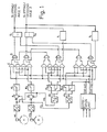
- Fig 1 is a partial view of a circuit diagram of an example of a control system for carrying out the inventive method
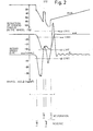
- Fig 2 is a diagram produced by a recording measuring equipment in a test for application of the inventive method and with the positions of the limit values indicated for the various parameters.
- the test refers to breaking with fully developed breaking force and sudden change of the adhesion from >0.3 to ⁇ 0.1.
- the present invention is primarily intended to be applied in vehicle drive systems in which all wheels or wheel axles are individually driveable and breakable. This might for instance be the case in electrically driven locomotives but also in other locomotives and vehicles having hydrostatic power transmission between e.g. an internal combustion engine and a number of wheels or wheel axles.
- a control device which preferably comprises an analog portion and a digital portion.
- To the analog portion belong first of all revolution counting means for the respective wheels or wheel axles, which means might be of a type known per se and therefore not further illustrated in the drawings.
- Said revolution counting means preferably consist of electromagnetic means, so-called pick-ups.
- the revolution counting means emit output signals corresponding to the rotary speeds or number of revolutions ⁇ 1 , ⁇ 2 for the respective wheels.
- the analog portion furthermore comprises not further illustrated acceleration-measuring means which are intended to determine the acceleration on the basis of the output signals from the revolution counting means.
- said acceleration-measuring means are constituted of known deriving circuits for said output signals known per se so as to thereby provide acceleration output signals ⁇ 1 , ⁇ 2 .
- summation points A 1 , A 2 is formed the differential between the output signals of the revolution counting means and after said summation points A1, A 2 are arranged comparators, particularly comparators K 1 , K 21 adapted to receive the resulting signal from the summation points A 1 , A 2 obtained from a speed differential, if any.
- the comparators K1, K 2 are adapted to carry out several functions. They compare the resulting revolution signals and determine the value of the highest number of revolutions and the lowest, respectively and also determine the differential between the highest and lowest number of revolutions. Furthermore, the comparators K,, K 2 are made such that they determine whether said differential thereby exceeds a predetermined limit value, in which case they emit an output signal, otherwise not.
- comparators K 3 , K 4 , K 5 , K 6 which are made such that when any of the acceleration output signals ⁇ 1 , ⁇ 2 exhibits a too great positive value (acceleration) or negative value (deceleration) an output signal is obtained which indicates which wheel or axle that has accelerated and which wheel or axle that has decelerated.
- the comparators K 1 -K 6 are connected AND- and OR-circuits C and D, respectively, for determining on the basis of the respective output signal from the aforementioned which wheel or which wheelaxle that has too great acceleration or too great number of revolutions relative the other wheels or wheel axles and which wheel or wheel axle that has too low acceleration or too low number of revolutions relative the other wheels or wheel axles.
- the respective OR-circuit is then connected to a setting means S 1 , S2 which suitably is constituted by an electric switch means known per se for a purpose which will be further evident from the following.
- a transducer for the determining control parameter such as the hydraulic system pressure as far as a hydrostatic power transmission is concerned, or the current in an electric traction system, and on the other a detecting means (not illustrated, too) for the direction of travel of the vehicle as selected by the driver.
- the outputs from said two last-mentioned means as well as the outputs from the setting means S 1 , S 2 and from the acceleration measuring means are carried to the digital portion, which constitutes a signal processing device, such as a simple micro-processor of known type.
- the digital portion is adapted to determine on the basis of the outputs from the control parameter transducer and the detecting means for the direction of vehicle travel whether acceleration or deceleration of the vehicle is to be expected at the wheels or wheel axles and hence also whether slipping or skidding is to be expected, and then to form an electric expectation output signal for the expected condition.
- this is carried out in a circuit including a comparator and an "EXCLUSIVE-OR"-circuit.
- the digital portion is adapted to correlate, when acceleration is expected, the expectation output signal to the signal of the wheel or the wheel axle which has too high a rotary speed in relation to the other wheels or axles, while-when deceleration is expected said digital portions correlate to the signal of the wheel or wheel axle which has a rotary speed or number of revolutions which is lower than that of other wheels or axles. Said correlation results in an output signal which "sets" the condition of the setting means S 1 and S 2 , respectively, so as to thereby release desired measures as to the actual control parameter (pressure reduction, current reduction).
- the output signal from the setting means as to slipping or alternatively locking of the respective wheel axle or wheel is held as known per se momentarily, even if the releasing signal ceases.
- certain restoration conditions are namely superposed on the digital portion.
- the expectation output signal is namely correlated to the output signal from the acceleration measuring means of the wheel or wheel axle in question and provides a cancellation of the measure determined by the setting means S 1 , S 2 not until the acceleration .output signal alters its sign.
- the digital portion again releases an output signal from the comparator K 1 and K 2 respectively and the operation sequence is repeated.
- timing means T 1 , T 2 might be utilized. Said timing means T 1 , T 2 are then adapted to restore the setting means S 1 , S 2 after a predetermined period of time, soch as one second should no "normal" restoring already has occurred. If a slipping or skidding is present as indicated by the difference in numbers of revolutions, when the timing means restore the setting means S 1 , S 2 , it is immediately released a new indication by the actual setting means S 1 or S 2 .
- the timing means hence contribute to a rapid cancellation of erroneous operations, if any, of the control device.
- an expectation output signal is provided dependent on the actual direction of travel of the vehicle, said output signal when acceleration is expected brings the wheel, which has too high a rotary speed in relation to other wheels or wheel axles and/or exhibits too great acceleration in comparison with a calculated maximum possible acceleration, to release an indication of slipping by means of which steps then are taken for elimination of said slipping.
- the wheel which has the lowest relative number of revolutions or too great negative acceleration in comparison with a calculated possible acceleration is brought to release an indication of skidding, by means of which steps likewise are taken for eliminating said skidding.
- the respective indication is held until, when acceleration is expected, the slipping wheel exhibits negative acceleration, and when deceleration is expected the skidding wheel exhibits positive acceleration.
- the rotary speed differentials between the. wheels thereby have to lie within a predetermined range of limit values such that the method might respond also to so-called "creeping" slipping and skidding, respectively, of one or more wheels or wheel axles of the vehicle.
Landscapes
- Engineering & Computer Science (AREA)
- Transportation (AREA)
- Mechanical Engineering (AREA)
- Chemical & Material Sciences (AREA)
- Combustion & Propulsion (AREA)
- Microelectronics & Electronic Packaging (AREA)
- Physics & Mathematics (AREA)
- Fluid Mechanics (AREA)
- Regulating Braking Force (AREA)
- Electric Propulsion And Braking For Vehicles (AREA)
- Arrangement And Driving Of Transmission Devices (AREA)
- Control Of Vehicle Engines Or Engines For Specific Uses (AREA)
Applications Claiming Priority (2)
| Application Number | Priority Date | Filing Date | Title |
|---|---|---|---|
| SE8302686 | 1983-05-10 | ||
| SE8302686A SE443539B (sv) | 1983-05-10 | 1983-05-10 | Forfarande och anordning for att forhindra slirning och/eller glidning mellan driv- och bromsbara hjul och underlaget vid fordonsdrivsystem |
Publications (3)
| Publication Number | Publication Date |
|---|---|
| EP0126051A2 true EP0126051A2 (de) | 1984-11-21 |
| EP0126051A3 EP0126051A3 (en) | 1986-10-08 |
| EP0126051B1 EP0126051B1 (de) | 1988-08-10 |
Family
ID=20351163
Family Applications (1)
| Application Number | Title | Priority Date | Filing Date |
|---|---|---|---|
| EP19840850147 Expired EP0126051B1 (de) | 1983-05-10 | 1984-05-09 | Verfahren und Anlage zum Verhüten des Schleuderns und des Gleitens zwischen antreibbaren und bremsbaren Rädern und der Stutzfläche in Kraftfahrzeugantriebssystemen |
Country Status (3)
| Country | Link |
|---|---|
| EP (1) | EP0126051B1 (de) |
| DE (1) | DE3473252D1 (de) |
| SE (1) | SE443539B (de) |
Cited By (4)
| Publication number | Priority date | Publication date | Assignee | Title |
|---|---|---|---|---|
| FR2589413A1 (fr) * | 1985-11-05 | 1987-05-07 | Honda Motor Co Ltd | Vehicule a quatre roues motrices comportant un systeme antiblocage a sections de commande avant et arriere |
| EP0270092A3 (en) * | 1986-12-02 | 1988-07-20 | Sumitomo Electric Industries Limited | Wheel spin control apparatus |
| EP0254943A3 (en) * | 1986-07-24 | 1988-11-23 | Mazda Motor Corporation | Vehicle slip control apparatus |
| EP4219252A1 (de) * | 2022-01-28 | 2023-08-02 | Volvo Truck Corporation | Verfahren zur steuerung eines schwerlastfahrzeugs |
Family Cites Families (4)
| Publication number | Priority date | Publication date | Assignee | Title |
|---|---|---|---|---|
| US3398994A (en) * | 1966-09-14 | 1968-08-27 | Westinghouse Air Brake Co | Anti-skid wheel control system for railway cars |
| US3832013A (en) * | 1970-09-30 | 1974-08-27 | Bendix Corp | Anti-skid control system for fluid pressure brakes |
| IT1002135B (it) * | 1972-12-06 | 1976-05-20 | Teldix Gmbh | Sistema di regolazione di antibloc caggio per veicoli |
| US4071282A (en) * | 1976-02-04 | 1978-01-31 | Vapor Corporation | Slip-slide detector system for railway car wheels |
-
1983
- 1983-05-10 SE SE8302686A patent/SE443539B/sv not_active IP Right Cessation
-
1984
- 1984-05-09 DE DE8484850147T patent/DE3473252D1/de not_active Expired
- 1984-05-09 EP EP19840850147 patent/EP0126051B1/de not_active Expired
Cited By (6)
| Publication number | Priority date | Publication date | Assignee | Title |
|---|---|---|---|---|
| FR2589413A1 (fr) * | 1985-11-05 | 1987-05-07 | Honda Motor Co Ltd | Vehicule a quatre roues motrices comportant un systeme antiblocage a sections de commande avant et arriere |
| EP0254943A3 (en) * | 1986-07-24 | 1988-11-23 | Mazda Motor Corporation | Vehicle slip control apparatus |
| EP0270092A3 (en) * | 1986-12-02 | 1988-07-20 | Sumitomo Electric Industries Limited | Wheel spin control apparatus |
| US4823269A (en) * | 1986-12-02 | 1989-04-18 | Sumitomo Electric Industries, Ltd. | Wheel spin control apparatus |
| EP4219252A1 (de) * | 2022-01-28 | 2023-08-02 | Volvo Truck Corporation | Verfahren zur steuerung eines schwerlastfahrzeugs |
| US12617407B2 (en) | 2022-01-28 | 2026-05-05 | Volvo Truck Corporation | Method for controlling a heavy-duty vehicle |
Also Published As
| Publication number | Publication date |
|---|---|
| SE443539B (sv) | 1986-03-03 |
| SE8302686D0 (sv) | 1983-05-10 |
| EP0126051A3 (en) | 1986-10-08 |
| EP0126051B1 (de) | 1988-08-10 |
| DE3473252D1 (en) | 1988-09-15 |
| SE8302686L (sv) | 1984-11-11 |
Similar Documents
| Publication | Publication Date | Title |
|---|---|---|
| EP0291217B1 (de) | Verfahren zur Feststellung eines leeren Reifens auf einem Fahrzeug | |
| US5502433A (en) | Method and device for detecting hydroplaning conditions for vehicle tires | |
| CA2110964C (en) | Method and device for detecting a deflated tire | |
| US5442331A (en) | Method and device for detecting a deflated tire by comparing angular velocity and forward/backward speed data with a data table | |
| GB2243657A (en) | A method for monitoring the friction between the roadway and the tyres of driven motor vehicle wheels | |
| JPH09509500A (ja) | 回転数センサにおけるエラーの検出方法 | |
| JPS6364664B2 (de) | ||
| JP3409389B2 (ja) | 路面摩擦係数推定装置 | |
| EP0075932A2 (de) | Bremsantiblockiersystem das eine Sicherheitseinrichtung aufweist | |
| US6682153B2 (en) | Method for detecting output-stuck fault of car body acceleration sensor, apparatus for detecting output-stuck fault of car body acceleration sensor, and anti-lock braking system for car | |
| EP0374924A2 (de) | Antiblockiersteuerungssystem | |
| US5290095A (en) | Wheel lock detection arrangement for multiple-axle railway vehicles | |
| EP0126051B1 (de) | Verfahren und Anlage zum Verhüten des Schleuderns und des Gleitens zwischen antreibbaren und bremsbaren Rädern und der Stutzfläche in Kraftfahrzeugantriebssystemen | |
| CA2078495C (en) | Method of inspecting limited slip differential for vehicle | |
| US6302500B1 (en) | Device for detecting vehicle speed of four-wheeled vehicles for use in ABS | |
| US4774668A (en) | Anti-skid control system for motor vehicles | |
| US4992945A (en) | Method and apparatus for distinguishing skidding wheels of a vehicle from drive train vibrations | |
| KR102702825B1 (ko) | 차량 제동배분 장치 및 이를 이용한 차량 제동배분 방법 | |
| US6554376B2 (en) | Method and device for adjusting the braking and/or driving effect on the wheels of a motor vehicle | |
| JP4004184B2 (ja) | 車輪速異常検出装置 | |
| JPS647259B2 (de) | ||
| JP2557751B2 (ja) | アンチロックブレーキの検査方法及び検査装置 | |
| KR970009631B1 (ko) | 회전속도감지기의 작용능력 모니터방법 | |
| JPS63214548A (ja) | 車両用車速センサの故障診断装置 | |
| KR0180588B1 (ko) | 차량의 클러치 마모 경고장치와 방법 |
Legal Events
| Date | Code | Title | Description |
|---|---|---|---|
| PUAI | Public reference made under article 153(3) epc to a published international application that has entered the european phase |
Free format text: ORIGINAL CODE: 0009012 |
|
| AK | Designated contracting states |
Designated state(s): CH DE FR GB IT LI |
|
| PUAL | Search report despatched |
Free format text: ORIGINAL CODE: 0009013 |
|
| AK | Designated contracting states |
Kind code of ref document: A3 Designated state(s): CH DE FR GB IT LI |
|
| 17P | Request for examination filed |
Effective date: 19861114 |
|
| 17Q | First examination report despatched |
Effective date: 19870827 |
|
| GRAA | (expected) grant |
Free format text: ORIGINAL CODE: 0009210 |
|
| AK | Designated contracting states |
Kind code of ref document: B1 Designated state(s): CH DE FR GB IT LI |
|
| ITF | It: translation for a ep patent filed | ||
| REF | Corresponds to: |
Ref document number: 3473252 Country of ref document: DE Date of ref document: 19880915 |
|
| ET | Fr: translation filed | ||
| PLBI | Opposition filed |
Free format text: ORIGINAL CODE: 0009260 |
|
| 26 | Opposition filed |
Opponent name: ROBERT BOSCH GMBH Effective date: 19890508 |
|
| PGFP | Annual fee paid to national office [announced via postgrant information from national office to epo] |
Ref country code: GB Payment date: 19900508 Year of fee payment: 7 |
|
| PGFP | Annual fee paid to national office [announced via postgrant information from national office to epo] |
Ref country code: FR Payment date: 19900514 Year of fee payment: 7 |
|
| PGFP | Annual fee paid to national office [announced via postgrant information from national office to epo] |
Ref country code: DE Payment date: 19900528 Year of fee payment: 7 Ref country code: CH Payment date: 19900528 Year of fee payment: 7 |
|
| ITTA | It: last paid annual fee | ||
| RDAG | Patent revoked |
Free format text: ORIGINAL CODE: 0009271 |
|
| STAA | Information on the status of an ep patent application or granted ep patent |
Free format text: STATUS: PATENT REVOKED |
|
| REG | Reference to a national code |
Ref country code: CH Ref legal event code: PL |
|
| 27W | Patent revoked |
Effective date: 19910805 |
|
| GBPR | Gb: patent revoked under art. 102 of the ep convention designating the uk as contracting state |