EP0126410A2 - Assemblage traverse-montant à l'aide d'un élément d'assemblage en deux pièces - Google Patents
Assemblage traverse-montant à l'aide d'un élément d'assemblage en deux pièces Download PDFInfo
- Publication number
- EP0126410A2 EP0126410A2 EP84105506A EP84105506A EP0126410A2 EP 0126410 A2 EP0126410 A2 EP 0126410A2 EP 84105506 A EP84105506 A EP 84105506A EP 84105506 A EP84105506 A EP 84105506A EP 0126410 A2 EP0126410 A2 EP 0126410A2
- Authority
- EP
- European Patent Office
- Prior art keywords
- profile
- bolt
- stem
- grooves
- insertion profile
- Prior art date
- Legal status (The legal status is an assumption and is not a legal conclusion. Google has not performed a legal analysis and makes no representation as to the accuracy of the status listed.)
- Granted
Links
Images


Classifications
-
- E—FIXED CONSTRUCTIONS
- E04—BUILDING
- E04H—BUILDINGS OR LIKE STRUCTURES FOR PARTICULAR PURPOSES; SWIMMING OR SPLASH BATHS OR POOLS; MASTS; FENCING; TENTS OR CANOPIES, IN GENERAL
- E04H15/00—Tents or canopies, in general
- E04H15/18—Tents having plural sectional covers, e.g. pavilions, vaulted tents, marquees, circus tents; Plural tents, e.g. modular
-
- E—FIXED CONSTRUCTIONS
- E04—BUILDING
- E04B—GENERAL BUILDING CONSTRUCTIONS; WALLS, e.g. PARTITIONS; ROOFS; FLOORS; CEILINGS; INSULATION OR OTHER PROTECTION OF BUILDINGS
- E04B1/00—Constructions in general; Structures which are not restricted either to walls, e.g. partitions, or floors or ceilings or roofs
- E04B1/38—Connections for building structures in general
- E04B1/58—Connections for building structures in general of bar-shaped building elements
- E04B1/5825—Connections for building structures in general of bar-shaped building elements with a closed cross-section
- E04B1/5831—Connections for building structures in general of bar-shaped building elements with a closed cross-section of substantially rectangular form
-
- E—FIXED CONSTRUCTIONS
- E04—BUILDING
- E04H—BUILDINGS OR LIKE STRUCTURES FOR PARTICULAR PURPOSES; SWIMMING OR SPLASH BATHS OR POOLS; MASTS; FENCING; TENTS OR CANOPIES, IN GENERAL
- E04H15/00—Tents or canopies, in general
- E04H15/32—Parts, components, construction details, accessories, interior equipment, specially adapted for tents, e.g. guy-line equipment, skirts, thresholds
- E04H15/64—Tent or canopy cover fastenings
- E04H15/642—Tent or canopy cover fastenings with covers held by elongated fixing members locking in longitudinal recesses of a frame
- E04H15/644—Tent or canopy cover fastenings with covers held by elongated fixing members locking in longitudinal recesses of a frame the fixing members being a beading
-
- E—FIXED CONSTRUCTIONS
- E04—BUILDING
- E04B—GENERAL BUILDING CONSTRUCTIONS; WALLS, e.g. PARTITIONS; ROOFS; FLOORS; CEILINGS; INSULATION OR OTHER PROTECTION OF BUILDINGS
- E04B1/00—Constructions in general; Structures which are not restricted either to walls, e.g. partitions, or floors or ceilings or roofs
- E04B1/38—Connections for building structures in general
- E04B1/58—Connections for building structures in general of bar-shaped building elements
- E04B1/5825—Connections for building structures in general of bar-shaped building elements with a closed cross-section
- E04B2001/5856—Connections for building structures in general of bar-shaped building elements with a closed cross-section using the innerside thereof
Definitions
- the invention relates to a transom-stem connection by means of a two-part connecting element in a scaffold construction made of hollow profiles equipped with keder grooves at least for the transoms, with a push connection running in the transom direction, as is given in particular when creating light metal supporting frameworks for the respective eaves corner in tent halls.
- the task on which this roof truss training is based is to design the connection area mentioned in such a way that the required dimensional stability is achieved in this area in a simple manner without the functionality of the roof truss being impaired thereby.
- the insertion profile is screwed to the lower wall while at the same time securing a non-positioned molded part lying outside the truss or transom profile.
- DE-OS 29 28 751 from the same applicant provides more information about this molding. It is the molded part 5, in which transverse, ie perpendicular to the bolt course, guide carriages for receiving guide rails, which are carried by the molded part 4 associated with the handle, are provided.
- the "Höcker special aluminum shear connections" brochure shows the two interlocking molded parts and the fastening of a part arranged inside the profile by means of riveted connections within the circle shown on the brochure.
- GM 80 00 952 indicates a shear connection between the handle and the bolt that runs in the bolt direction.
- the disadvantages of the shear connections provided transversely to the direction of the transom were critically assessed, with particular reference being made to the static weaknesses of such associations, since the length of the connections is ultimately determined by the narrow sides of the transom profile, and also to the risk of, for example, transport-related injury of the two connecting elements provided here, which are arranged parallel and at a small distance from one another, and even slight damage can negate the functionality of these connections by tilting associated therewith.
- the solution to this problem according to the invention provides that the bolt is opened at least over the length of the bolt insertion profile between the lower keder grooves, wherein between the wall flanges of the insertion profile engaging in the bolt and its walls and the area of the guide slide, a shaped groove for receiving the The interior of the profile-oriented area of the double-sided welt grooves is provided in the insert profile,
- the opening of the transom base between the welt grooves creates an insertion gap for the transom insert profile equipped with shaped grooves, this profile being positively supported by the engagement of the shaped grooves over the area of the welt groove directed towards the profile interior through the transom profile in the direction of the vertical. This eliminates the need for screwing together the transom profile, the insert profile and the guide carriage.
- the guide carriage itself is integrated in the plug-in profile, so that this is also not required as an independent part.
- the wall flanges of the plug-in profile lying against the transom walls are made in the usual way, e.g. connected by rivets.
- the T-shaped recess forming the guide carriage in the insertion profile essentially within the locking profile.
- the volume of the parts emerging from the bolt is thus reduced to a minimum, so that the bulkiness when loading preassembled bolts is reduced and the slide guide is largely protected against injuries.
- the number of individual parts required is further reduced by the design of a stem insertion profile as a coherent unit. This is particularly true when the stem insertion profile is an integrated, extruded unit.
- the profile should be cut into sections according to the inclination, in the supplementary angle to the vertical, in sections according to the engagement width, this embodiment only addresses a procedure which is preferably to be referred to as i.
- Both profiles, the stem insertion profile and the bolt insertion profile are usually made of aluminum.
- the side boundaries of the part of the bolt insertion profile protruding from the bolt support the lower lips of the welt grooves, spanning their entire width.
- the part of the bolt insert profile introduced into the bolt has a fork shape which either opens into wall flanges, but is designed as a box profile with side walls parallel to the bolt walls.
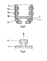
- the scaffold structure 1 is formed from the stems 2 and the bars 3, the connection between each stalk 2 and one bar 3 being made by inserting the stem insertion profile 4 into the bolt insertion profile 5.
- the bar 3 is formed by a hollow profile equipped with welt grooves 3.1, in the case of this example a similarly dimensioned and identically designed hollow profile is also proposed for the handle 2, in the interest of standardizing the material inventory.
- the stem insertion profile 4 is delimited at the top by a T-shaped guide rail 4.1 formed on a support plane, the support plane carrying the web of a fork flange 4.2 which can be inserted into the stem 2.
- the stem insertion profile 4 is an integrated unit, the limit of which is directed towards the bolt and is oriented in its position at an angle to the vertical stem guide in accordance with the predetermined roof inclination.
- the connection of the stem insertion profile 4 with the stem 2 takes place in the case of this example by rivet connections 4.3.
- the transom insert profile 5 is provided on both sides with a shaped groove 5.4 which, after removal of the base from the transom 3 - which must be carried out at least over the length of the transom insertion profile 5 - can be pushed over the region of the welt grooves 3.1 formed on both sides towards the profile interior. After insertion, the latch 3 and latch insertion profile 5 are positively connected perpendicular to the latter.
- the bolt insertion profile 5 is provided with wall flanges 5.2 directed outwards, which in turn are connected to the inner side walls of the bolt 3 by rivet connections 5.3.
- the bolt insertion profile 5 partially forms a box support 5.6, which is also connected by rivet connections 5.3 to the side walls of the bolt 3.
- the number and strength of the rivets or the number of rows of rivets vary depending on the load conditions
- the dimensions and shape of the T-shaped guide rail 4.1 and the recess 5.1 forming the guide carriage correspond.
- the recess 5.1 forming the guide carriage is arranged essentially within the part of the plug-in profile 5 lying in the latch 3.
- the insertion profile 5 ends with a flange-like limitation of the shaped grooves 5.4.
- the slide guide is largely secured against injury in this embodiment, whereby, as mentioned, there are also static advantages.
Landscapes
- Engineering & Computer Science (AREA)
- Architecture (AREA)
- Civil Engineering (AREA)
- Structural Engineering (AREA)
- Physics & Mathematics (AREA)
- Electromagnetism (AREA)
- Mutual Connection Of Rods And Tubes (AREA)
- Body Structure For Vehicles (AREA)
- Rod-Shaped Construction Members (AREA)
- Tents Or Canopies (AREA)
Priority Applications (1)
| Application Number | Priority Date | Filing Date | Title |
|---|---|---|---|
| AT84105506T ATE37921T1 (de) | 1983-05-21 | 1984-05-15 | Riegel-stielverbindung durch ein zweiteiliges verbindungselement. |
Applications Claiming Priority (2)
| Application Number | Priority Date | Filing Date | Title |
|---|---|---|---|
| DE19833318655 DE3318655A1 (de) | 1983-05-21 | 1983-05-21 | Riegel-stielverbindung durch ein zweiteiliges verbindungselement |
| DE3318655 | 1983-05-21 |
Publications (3)
| Publication Number | Publication Date |
|---|---|
| EP0126410A2 true EP0126410A2 (fr) | 1984-11-28 |
| EP0126410A3 EP0126410A3 (en) | 1986-06-11 |
| EP0126410B1 EP0126410B1 (fr) | 1988-10-12 |
Family
ID=6199648
Family Applications (1)
| Application Number | Title | Priority Date | Filing Date |
|---|---|---|---|
| EP84105506A Expired EP0126410B1 (fr) | 1983-05-21 | 1984-05-15 | Assemblage traverse-montant à l'aide d'un élément d'assemblage en deux pièces |
Country Status (3)
| Country | Link |
|---|---|
| EP (1) | EP0126410B1 (fr) |
| AT (1) | ATE37921T1 (fr) |
| DE (2) | DE3318655A1 (fr) |
Cited By (3)
| Publication number | Priority date | Publication date | Assignee | Title |
|---|---|---|---|---|
| EP0261532A1 (fr) * | 1986-09-22 | 1988-03-30 | Siegfried Kraus | Dispositif d'assemblage d'angle pour profilés creux |
| EP0301987A1 (fr) * | 1987-07-27 | 1989-02-01 | Bator S.A. | Dispostif d'assemblage d'un arbalétrier de ferme avec un poteau, pour la réalisation de charpentes et structures |
| EP0429931A3 (en) * | 1989-11-23 | 1992-04-22 | Schueco International Kg | T-connecting between two profiles, mainly between upright and transom of a wall |
Family Cites Families (5)
| Publication number | Priority date | Publication date | Assignee | Title |
|---|---|---|---|---|
| AT179640B (de) * | 1953-02-21 | 1954-09-25 | Oesterreichische Metallwerke A | Metallbauverbindung |
| DE2314866A1 (de) * | 1972-03-30 | 1974-02-14 | Straub Siegfried | Verbindungssystem |
| DE2719490C2 (de) * | 1977-05-02 | 1983-01-05 | Karl Höcker Stahlbau KG, 4902 Bad Salzuflen | Dachbinder eines Zelt-Traggerüstes |
| DE2928751C2 (de) * | 1979-07-17 | 1983-12-01 | Karl Höcker Stahlbau GmbH & Co KG, 4902 Bad Salzuflen | Traggerüst für ein Zelt o.dgl. |
| DE8000952U1 (de) * | 1980-01-16 | 1980-04-10 | Roeder, Edwin, 6470 Buedingen | Zweiteiliges verbindungselement fuer die herstellung jeweils einer riegel- und stielverbindung einer geruestkonstruktion |
-
1983
- 1983-05-21 DE DE19833318655 patent/DE3318655A1/de not_active Withdrawn
-
1984
- 1984-05-15 AT AT84105506T patent/ATE37921T1/de not_active IP Right Cessation
- 1984-05-15 EP EP84105506A patent/EP0126410B1/fr not_active Expired
- 1984-05-15 DE DE8484105506T patent/DE3474576D1/de not_active Expired
Cited By (4)
| Publication number | Priority date | Publication date | Assignee | Title |
|---|---|---|---|---|
| EP0261532A1 (fr) * | 1986-09-22 | 1988-03-30 | Siegfried Kraus | Dispositif d'assemblage d'angle pour profilés creux |
| EP0301987A1 (fr) * | 1987-07-27 | 1989-02-01 | Bator S.A. | Dispostif d'assemblage d'un arbalétrier de ferme avec un poteau, pour la réalisation de charpentes et structures |
| FR2618819A1 (fr) * | 1987-07-27 | 1989-02-03 | Bator Sa | Dispositif d'assemblage d'un arbaletrier de ferme avec un poteau, pour la realisation de charpentes et structures |
| EP0429931A3 (en) * | 1989-11-23 | 1992-04-22 | Schueco International Kg | T-connecting between two profiles, mainly between upright and transom of a wall |
Also Published As
| Publication number | Publication date |
|---|---|
| EP0126410B1 (fr) | 1988-10-12 |
| ATE37921T1 (de) | 1988-10-15 |
| DE3318655A1 (de) | 1984-11-22 |
| DE3474576D1 (en) | 1988-11-17 |
| EP0126410A3 (en) | 1986-06-11 |
Similar Documents
| Publication | Publication Date | Title |
|---|---|---|
| EP0784126B1 (fr) | Construction d'ossature faite de barres profilées | |
| DE3024410C2 (de) | Frachtbehälter, insbesondere für Lufttransporte | |
| EP0864489B1 (fr) | Elément de plancher | |
| EP0300399A2 (fr) | Plateforme d'échafaudage composé de profilés extrudés en métal léger | |
| DE69226207T2 (de) | Verbesserungen an regalen | |
| DE10012690C1 (de) | Profilverbinder für Brandschutzkonstruktionen | |
| EP0126410B1 (fr) | Assemblage traverse-montant à l'aide d'un élément d'assemblage en deux pièces | |
| DE3539507A1 (de) | Geruestrahmentafel | |
| DE2604320C3 (de) | Bauelementensatz für ein Hallenbauwerk, insbesondere ein landwirtschaftliches Stallbauwerk | |
| DE68903348T2 (de) | Aufbauten vom typ sattelauflieger mit plane. | |
| EP0451616B1 (fr) | Plate-forme d'échafaudage | |
| EP0736648B1 (fr) | Echafaudage | |
| DE8315104U1 (de) | Riegel-stielverbinder | |
| EP4379169A1 (fr) | Système de cadre vertical pour échafaudage de système | |
| DE19712278A1 (de) | Bodenelement | |
| DE3701618C2 (de) | Auffahrschiene für Verladebrücke | |
| DE8305623U1 (de) | Geruestbohle | |
| DE29916844U1 (de) | Türschwelle | |
| DE3912484C2 (fr) | ||
| EP4562256B1 (fr) | Agencement de composants d'échafaudage pour un échafaudage | |
| EP0268197A2 (fr) | Echafaudage, plus spécialement échafaudage pour le bâtiment | |
| DE8000952U1 (de) | Zweiteiliges verbindungselement fuer die herstellung jeweils einer riegel- und stielverbindung einer geruestkonstruktion | |
| EP0178258A1 (fr) | Châssis de wagon de chemin de fer | |
| DE29621492U1 (de) | Baukonstruktion für einen Turm mit Wendeltreppe | |
| DE2712752A1 (de) | Wagenkasten fuer grossraumfahrzeuge, insbesondere omnibusse |
Legal Events
| Date | Code | Title | Description |
|---|---|---|---|
| PUAI | Public reference made under article 153(3) epc to a published international application that has entered the european phase |
Free format text: ORIGINAL CODE: 0009012 |
|
| AK | Designated contracting states |
Designated state(s): AT BE CH DE FR GB IT LI LU NL SE |
|
| PUAL | Search report despatched |
Free format text: ORIGINAL CODE: 0009013 |
|
| AK | Designated contracting states |
Kind code of ref document: A3 Designated state(s): AT BE CH DE FR GB IT LI LU NL SE |
|
| 17P | Request for examination filed |
Effective date: 19861209 |
|
| 17Q | First examination report despatched |
Effective date: 19880301 |
|
| GRAA | (expected) grant |
Free format text: ORIGINAL CODE: 0009210 |
|
| AK | Designated contracting states |
Kind code of ref document: B1 Designated state(s): AT BE CH DE FR GB IT LI LU NL SE |
|
| REF | Corresponds to: |
Ref document number: 37921 Country of ref document: AT Date of ref document: 19881015 Kind code of ref document: T |
|
| ITF | It: translation for a ep patent filed | ||
| REF | Corresponds to: |
Ref document number: 3474576 Country of ref document: DE Date of ref document: 19881117 |
|
| ET | Fr: translation filed | ||
| GBT | Gb: translation of ep patent filed (gb section 77(6)(a)/1977) | ||
| PG25 | Lapsed in a contracting state [announced via postgrant information from national office to epo] |
Ref country code: LU Free format text: LAPSE BECAUSE OF NON-PAYMENT OF DUE FEES Effective date: 19890531 |
|
| PLBE | No opposition filed within time limit |
Free format text: ORIGINAL CODE: 0009261 |
|
| STAA | Information on the status of an ep patent application or granted ep patent |
Free format text: STATUS: NO OPPOSITION FILED WITHIN TIME LIMIT |
|
| 26N | No opposition filed | ||
| PGFP | Annual fee paid to national office [announced via postgrant information from national office to epo] |
Ref country code: SE Payment date: 19900509 Year of fee payment: 7 Ref country code: LU Payment date: 19900509 Year of fee payment: 7 |
|
| PGFP | Annual fee paid to national office [announced via postgrant information from national office to epo] |
Ref country code: AT Payment date: 19900515 Year of fee payment: 7 |
|
| PGFP | Annual fee paid to national office [announced via postgrant information from national office to epo] |
Ref country code: FR Payment date: 19900518 Year of fee payment: 7 |
|
| PGFP | Annual fee paid to national office [announced via postgrant information from national office to epo] |
Ref country code: CH Payment date: 19900521 Year of fee payment: 7 |
|
| ITTA | It: last paid annual fee | ||
| PGFP | Annual fee paid to national office [announced via postgrant information from national office to epo] |
Ref country code: NL Payment date: 19900531 Year of fee payment: 7 |
|
| PGFP | Annual fee paid to national office [announced via postgrant information from national office to epo] |
Ref country code: BE Payment date: 19900601 Year of fee payment: 7 |
|
| PGFP | Annual fee paid to national office [announced via postgrant information from national office to epo] |
Ref country code: GB Payment date: 19900608 Year of fee payment: 7 |
|
| PGFP | Annual fee paid to national office [announced via postgrant information from national office to epo] |
Ref country code: DE Payment date: 19910130 Year of fee payment: 7 |
|
| PG25 | Lapsed in a contracting state [announced via postgrant information from national office to epo] |
Ref country code: GB Effective date: 19910515 Ref country code: AT Effective date: 19910515 |
|
| PG25 | Lapsed in a contracting state [announced via postgrant information from national office to epo] |
Ref country code: SE Effective date: 19910516 |
|
| PG25 | Lapsed in a contracting state [announced via postgrant information from national office to epo] |
Ref country code: LI Effective date: 19910531 Ref country code: CH Effective date: 19910531 Ref country code: BE Effective date: 19910531 |
|
| BERE | Be: lapsed |
Owner name: RODER EDWIN Effective date: 19910531 |
|
| PG25 | Lapsed in a contracting state [announced via postgrant information from national office to epo] |
Ref country code: NL Effective date: 19911201 |
|
| GBPC | Gb: european patent ceased through non-payment of renewal fee | ||
| NLV4 | Nl: lapsed or anulled due to non-payment of the annual fee | ||
| PG25 | Lapsed in a contracting state [announced via postgrant information from national office to epo] |
Ref country code: FR Effective date: 19920131 |
|
| REG | Reference to a national code |
Ref country code: CH Ref legal event code: PL |
|
| PG25 | Lapsed in a contracting state [announced via postgrant information from national office to epo] |
Ref country code: DE Effective date: 19920303 |
|
| REG | Reference to a national code |
Ref country code: FR Ref legal event code: ST |
|
| EUG | Se: european patent has lapsed |
Ref document number: 84105506.4 Effective date: 19911209 |