EP0736648B1 - Echafaudage - Google Patents
Echafaudage Download PDFInfo
- Publication number
- EP0736648B1 EP0736648B1 EP96105043A EP96105043A EP0736648B1 EP 0736648 B1 EP0736648 B1 EP 0736648B1 EP 96105043 A EP96105043 A EP 96105043A EP 96105043 A EP96105043 A EP 96105043A EP 0736648 B1 EP0736648 B1 EP 0736648B1
- Authority
- EP
- European Patent Office
- Prior art keywords
- scaffold
- bearing
- horizontal
- crossmember
- lift
- Prior art date
- Legal status (The legal status is an assumption and is not a legal conclusion. Google has not performed a legal analysis and makes no representation as to the accuracy of the status listed.)
- Expired - Lifetime
Links
- 238000013461 design Methods 0.000 claims description 26
- 210000000078 claw Anatomy 0.000 claims description 9
- 238000006073 displacement reaction Methods 0.000 claims description 7
- 239000002184 metal Substances 0.000 claims description 6
- 239000012530 fluid Substances 0.000 claims description 3
- 238000009749 continuous casting Methods 0.000 claims 1
- 238000005058 metal casting Methods 0.000 claims 1
- 125000006850 spacer group Chemical group 0.000 claims 1
- 229910000831 Steel Inorganic materials 0.000 abstract description 3
- 239000010959 steel Substances 0.000 abstract description 3
- 210000003128 head Anatomy 0.000 description 44
- 239000000463 material Substances 0.000 description 7
- 230000002349 favourable effect Effects 0.000 description 5
- 238000004519 manufacturing process Methods 0.000 description 5
- 238000003466 welding Methods 0.000 description 5
- 238000005452 bending Methods 0.000 description 4
- 230000005540 biological transmission Effects 0.000 description 4
- 238000010276 construction Methods 0.000 description 4
- 230000002787 reinforcement Effects 0.000 description 4
- 238000012549 training Methods 0.000 description 4
- 238000005516 engineering process Methods 0.000 description 3
- 230000002265 prevention Effects 0.000 description 3
- 239000000725 suspension Substances 0.000 description 3
- 230000007704 transition Effects 0.000 description 3
- 230000015572 biosynthetic process Effects 0.000 description 2
- 239000002131 composite material Substances 0.000 description 2
- 238000005520 cutting process Methods 0.000 description 2
- 238000009826 distribution Methods 0.000 description 2
- 210000001061 forehead Anatomy 0.000 description 2
- 238000003780 insertion Methods 0.000 description 2
- 230000037431 insertion Effects 0.000 description 2
- 238000000034 method Methods 0.000 description 2
- 238000010422 painting Methods 0.000 description 2
- 230000008569 process Effects 0.000 description 2
- 230000003068 static effect Effects 0.000 description 2
- 238000004381 surface treatment Methods 0.000 description 2
- 239000002023 wood Substances 0.000 description 2
- 241001136792 Alle Species 0.000 description 1
- 241001295925 Gegenes Species 0.000 description 1
- 230000006978 adaptation Effects 0.000 description 1
- 230000000712 assembly Effects 0.000 description 1
- 238000000429 assembly Methods 0.000 description 1
- 238000004364 calculation method Methods 0.000 description 1
- 230000015556 catabolic process Effects 0.000 description 1
- 238000006731 degradation reaction Methods 0.000 description 1
- 230000001419 dependent effect Effects 0.000 description 1
- 238000011161 development Methods 0.000 description 1
- 230000018109 developmental process Effects 0.000 description 1
- 238000009434 installation Methods 0.000 description 1
- 230000003993 interaction Effects 0.000 description 1
- 230000007246 mechanism Effects 0.000 description 1
- 239000007769 metal material Substances 0.000 description 1
- 230000035515 penetration Effects 0.000 description 1
- 230000000284 resting effect Effects 0.000 description 1
- 230000003319 supportive effect Effects 0.000 description 1
- 238000012546 transfer Methods 0.000 description 1
Images







Classifications
-
- E—FIXED CONSTRUCTIONS
- E04—BUILDING
- E04G—SCAFFOLDING; FORMS; SHUTTERING; BUILDING IMPLEMENTS OR AIDS, OR THEIR USE; HANDLING BUILDING MATERIALS ON THE SITE; REPAIRING, BREAKING-UP OR OTHER WORK ON EXISTING BUILDINGS
- E04G1/00—Scaffolds primarily resting on the ground
- E04G1/15—Scaffolds primarily resting on the ground essentially comprising special means for supporting or forming platforms; Platforms
- E04G1/152—Platforms made of metal or with metal-supporting frame
-
- E—FIXED CONSTRUCTIONS
- E04—BUILDING
- E04G—SCAFFOLDING; FORMS; SHUTTERING; BUILDING IMPLEMENTS OR AIDS, OR THEIR USE; HANDLING BUILDING MATERIALS ON THE SITE; REPAIRING, BREAKING-UP OR OTHER WORK ON EXISTING BUILDINGS
- E04G7/00—Connections between parts of the scaffold
- E04G7/02—Connections between parts of the scaffold with separate coupling elements
- E04G7/28—Clips or connections for securing boards
-
- E—FIXED CONSTRUCTIONS
- E04—BUILDING
- E04G—SCAFFOLDING; FORMS; SHUTTERING; BUILDING IMPLEMENTS OR AIDS, OR THEIR USE; HANDLING BUILDING MATERIALS ON THE SITE; REPAIRING, BREAKING-UP OR OTHER WORK ON EXISTING BUILDINGS
- E04G1/00—Scaffolds primarily resting on the ground
- E04G1/15—Scaffolds primarily resting on the ground essentially comprising special means for supporting or forming platforms; Platforms
- E04G2001/158—Platforms supported by spigots which engage through holes in the platform
Definitions
- Scaffolds have stems, horizontal bars, and diagonal bars in order a stable and somewhat rigid Build space structure.
- the horizontal bars include Horizontal support bars, which are usually much shorter than the other horizontal bars.
- On the horizontal support bars become the scaffolding floors essential for scaffolding with the running and working areas for the actual Supported use of the scaffold.
- the interaction between the various elements of the supporting structure and at least in the tread plane torsionally rigid scaffolding floors can be used to stabilize the whole framework and essentials contribute. However, this is due to the circumstances of the Manufacturing, building, growing and using game to take into account.
- the scaffolding is either with vertical scaffolding frames, which are usually vertical and normal to the building wall be set up, or with individual stems and Node elements for the connection between stems and Horizontal and diagonal bars built.
- the invention deals with improved solutions Scaffolds with individual stems and with knot elements to connect the rods and as 'Module scaffolding' can be called.
- For the node elements various configurations are known. Below there are different arrangements with cup-like rings on the Stems in which the horizontal rods and hooks from above other horizontal elements and the connecting elements for Diagonal bars hooked in and with additional means be secured.
- the scaffolding floors are attached to the in different ways Horizontal support bars connected.
- One uses cylindrical support bars, are usually claw-like Hooks placed from above and mostly spring-loaded and / or locked holding fingers from below to prevent lifting recorded.
- the horizontal bars have wedge heads at their ends, which have a horizontal slot in the middle, which allows those below and above Push the headboard over the perforated disc from the side and then a wedge through the openings in the two Headboards and through the opening in the perforated disc stuck.
- top and Bottom can serve as a running and work surface double prism-shaped support elements on their end faces, which are also on the upper edge surfaces of the Vertical leg of the U-shaped, open at the top Horizontal bars are placed. With these there is also one Side shift possible if not additional Aids are applied.
- EP-A-0 308 882 discloses a scaffold floor part for bridges smaller, not parallel and more limited at right angles Running and working areas within a scaffold. there there are two horizontal support bars inside the scaffold Commitment. A first horizontal support bar is considered an after U-profile open at the top, which is attached to the wedge heads Perforated disks of the stems of the scaffold are connected and in which the scaffolding floor elements are hung using hooks become.
- horizontal support bars used which are welded to the scaffolding posts are and have vertical pins on which on the scaffold floors existing hangers are hooked in.
- the present invention has the technical problem or the task is based on scaffolding with support structure element arrangements of the type mentioned the holding, fixing and Supporting devices for scaffolding floors on the structure and associated Design elements so that manufacturing, Assembly, disassembly and use can be improved by the formation of the scaffolding and the support of the occurring Forces are improved and optimized.
- the invention further aims by Association of advantageous features from different Interchangeability and that arbitrary merging of elements of different To enable scaffolding systems, but above all on the other hand with a simple structure and cheap and inexpensive Manufacturing options a particularly good one, in several Directionally stable connection between the scaffold frame floors and the stems of the overall structure of the scaffold enable.
- the scaffold according to the invention is characterized by the features of given independent claim 1. advantageous Refinements and developments are the subject of dependent claims.
- consoles have a fastening on the scaffold arm and a little lower horizontal, usually loose, lower console support, with an inclined strut to the outer end of the Horizontal bar or horizontal support element of Console is connected so that all supporting forces on the Handle-side of the console can be introduced into the handle.
- the attachment to the respective one is known Node element. So far, U-shaped horizontal support elements with wedge heads attached to perforated disks provided or there are horizontal support elements with vertical pins and cup attachment common.
- a preferred alternative embodiment of the Scaffold according to the invention is characterized in that the support structure element arrangement designed with consoles is in each case instead of the horizontal support bar Have horizontal support element, with one at one end attached wedge head with one free end, with one on Fasten the wedge-head end and rest on the stem, approximately perpendicular to the horizontal support element Vertical strut leading oblique strut as well as with vertical pins, to the securing holes in the scaffolding or Console scaffolding floors are arranged in suitable dimensions.
- the console attachment with some known per se Wedge heads with above and below the perforated disc adjacent support surface and wedge bracing also offers Loose wedge provides great security against undesired falling of parts and especially in Connection with the connection secured via the pins between console scaffolding floors and horizontal support element one in overall strength and overall stiffness significantly improved overall scaffolding design.
- the special wedge head design for the Connection to the handle can be the loose handle system of the lower Struts are successfully used in a stable manner.
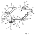
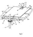
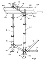
- the frame 30 has stems 31.1 and 31.2, which are in Support in the usual way on starting pieces 32.1 and 32.2. These in turn are based on nuts 33.1 and 33.2 adjustable support feet 34.1 and 34.2. In the usual Ways are also referred to as horizontal bars Horizontal longitudinal bar 35 and horizontal cross bar 36 and also diagonal bars 37 referred to as diagonal bars intended. These scaffolding elements are in the usual way often provided on the scaffold.
- a unusually wide horizontal support bar 45 To support the Scaffold floors 40.1 ... 4 of the first scaffold level 42 is a unusually wide horizontal support bar 45 provided, which with the help of provided by end Wedge heads 46.1 and 46.2 engage wedges 47.1 and 47.2 the perforated discs 48.1 and 48.2 of the stems 31.1 and 31.2 in which is wedged in the usual way with such scaffolding.
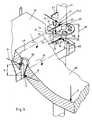
- This extremely stable and also safe against tipping forces Connection which the occurring forces with the Head end faces directly into the stem tube is 3 and 4 illustrated in more detail.
- the horizontal support bar 45 has a flat base support plate 50 and end pin support walls 51.1 and 51.2.
- Form cross struts 52 under the floor support plate 50 a structured, rigid element with an im essential box-shaped horizontal bar support tube 53, at the ends 54.1 and 54.2 the wedge heads 46.1 and 46.2 are preferably attached by welding. All Components usually exist for those as bulk goods used steel scaffolding. For those special costly, but for quick transportation as well the quick assembly and disassembly of inexpensive light metal frames they can also consist of light metal.
- the scaffolding floors 40.1 and 40.2 shown in Fig. 2 are just like the scaffolding floors 40.3 and 40.4 in Distance from its shorter end face 55 and from the long side vertical surfaces 56 in approximately the same Spaced, with securing holes or through-fixing openings 57.1 and 57.2 designed floor support means. These are usually designed with vertical sleeves 58. Wood, but also metal, can be used as scaffolding floor material or composite materials formed, common materials for Scaffold floors can be used.
- the dimensions of both the Scaffolding floor elements as well as for the arrangement of the Through-fixing openings 57.1 and 57.2 and their Distances from each other and from the forehead surfaces of the Scaffolding floors correspond to the scaffolding system to which they belong Usually include and the dimensions of the horizontal support bar are in accordance with those otherwise used To design scaffolding components.
- the free receiving length 67 is over the bearing surface 61 somewhat lower or at most equal to the height of 68 Tread 69 of the scaffolding floor 40 over the Support surface 61.
- Their upper ends 70 are more common Way slightly tapered to insert into the Through-fixing holes 57 to facilitate.
- Your Attachment ends 66 have an attachment length 73 that according to the usual dimensions and designs manufacturing technology favorable and the power ratios Appropriate attachment or as Transitional area for a formative training in one chipless forming process can serve.
- FIG. 3 illustrates the power transmission from one, as a result of the stress 3, bent scaffold floor 40 on the stem 31.
- the relatively precisely arranged Vertical sleeve 58 is supported in the area of the upper end 70 of the vertical pin 65 at the upper pin force application point 6 on one side and in the area of the fastening end 66 of the vertical pin 65 at the lower pin force application point 7 on the opposite side, making a relative large pin support spacing 5 between the two counter-acting pin support forces 8 and 9 of the applied moment 10 is to be considered.
- the upper head part 19 is supported with its upper inner limit 24.1 on one side of the wedge head 46 at the upper perforated disc force application point 13 with the upper perforated disc support force 11, while on the opposite side of the Wedge head 46 of the lower head part 20 with its lower Internal limitation 24.2 at the lower perforated disc force application point 14 with the lower perforated disc support force 12 supported. These support forces engage on the perforated disc the effective horizontal distance 4.
- the wedge head 46 is supported also on one side with its upper head part 19 at the upper point of tangential force 17 with the upper one tangential head support force while on the opposite side of the lower head part 20 at the lower Tangential force application point 18 with the lower one supports tangential head part supporting force.
- This Support forces engage in the effective vertical distance 29 Handle 31.
- the particularly advantageous design of the wedge head 46 leads in connection with the large effective distances of the Support force application points on perforated disk 48 (Horizontal distance 4) and in particular on the handle 31 (Vertical distance 2 and distance 29) to an optimal Power and torque transmission to the handle with which Consequence that greater static and dynamic loads are tolerable or that the corresponding scaffolding parts weight-optimized dimensions.
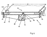
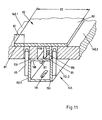
- the horizontal support bar 45 has on its underside Drain openings 84, so that a drain option for fluid media for surface treatment or for Rainwater is created.
- an anti-lift device 95 with a Bridging and anti-lift-off plate 80 provided, the support ends 81 with a support length 82 on the Support scaffolding floors 40.1 ... 4. In the middle are on its bottom securing hook 85 attached, which in Intervene with safety openings 86 with an elongated hole character.
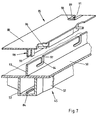
- FIG. 7 shows the security principle one of the bottom support plate 50 of the horizontal support bar 45 towering bending reinforcement and Locking washer 93 with hook slot 94 and above Engagement or insertion opening 97 is provided.
- To the another is under bridging and Anti-lift plate 80 also as a U-profile customizable double-bar arrangement 98, with receiving opening 99 to accommodate the locking plate 93, downwards designed, where appropriate Shift locking pins 96 are attached.
- anti-retraction means can also be used various types, especially with the help of Safety flap 89 may be provided.
- This design also shows the advantageous principles of modular scaffolding systems with perforated disks and themselves with their Support end faces on the tubes of the stems directly supporting wedge heads and from above and below with respect the wedge head elements inserted wedges.
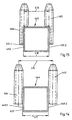
- the horizontal support bar has an upper, support surface 262 and lower on both sides of the horizontal support beam 245 running, parallel contact surfaces 263.1 and 263.2 from Pin and pad supports 264.1 and 264.2.
- the Boundary surface 262 is approximately at the same height 276 as the surface 277 of the scaffold floors 240.1 and 240.2 so that the distance 278 of the upper boundary surface 262 from the Support surface 263 approximately the thickness 279 of the scaffold floors 240 equivalent.
- the remaining features of the horizontal beam 245 correspond essentially to that described first Variant.
- they are cross struts 252 below the upper boundary surface 262 provided a structured, rigid element with the pin and pad support 264 and an im essential box-shaped horizontal bar support tube 253 form, with wedge heads at the ends in a conventional manner are preferably attached by welding.
- scaffolding elements can occur or make sense be part of the scaffold with scaffold floors 339 too provided with claws or Claws 343 on horizontal support legs that are open at the top Support 344 while next to it with its contact surface part 359 on the horizontal contact surface 361 overlying scaffold floors 340 with in Distance from the front and side surfaces
- Through-fixing openings 357.1 and 357.2 are provided, preferably with supportive, power-transmitting and enabling good conditions of use Vertical sleeves 358 are equipped.
- Such a Horizontal support bar 345 is shown in FIG. 13 with its two different scaffold frame floors 339 and 340 and Connection devices shown schematically.
- a wedge head 346 of here scaffolding system described in more detail with perforated disks 348 and Push-through wedges 347 shown.
- a fastening device be provided to the node element of the other scaffolding system fits.
- the vertical pins can in the connection area Horizontal support bars designed in different ways to meet the different requirements and constructive conditions of basic scaffolding systems To take into account.
- Figs. 14 and 15 can on the one hand in the area of their fastening ends 464 cylindrical vertical pins 463 may be provided.
- preferably semi-cylindrical Vertical pins 465 may be provided for one smaller pin spacing 416 or a larger width 418 of the horizontal bar 445 with its Horizontal bar support tube 453 technologically favorable can be realized.
- the vertical pins 463 and 465 are on the pin bearing walls 449.1 and 449.2 or 451.1 and 451.2 outside with their lower fastening ends 464 or 466 welded or in other ways by forming Education pronounced.
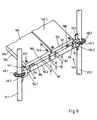
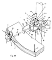
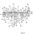
- the Console 500 deals with a wedge head 46.3.
- the Console 500 has a horizontal support element 501, which with one attached to the wedge head end 554.1, approximately extending perpendicular to the horizontal support element 501
- Vertical strut 502 and one from the free end or free end 554.2 to the vertical strut 502, in particular to their End 504 leading oblique strut 503 is equipped.
- the End 504 of the oblique strut 503 lies on the outside of the Tube 505 of the stem 31.2 loosely, while the wedge 47.3 the wedge head 46.3 in the usual way on the disc 48.2 sets.
- At the free end 554.2 of the horizontal support element 501 is a short vertical tube 506 fixed vertically with a weld seam 507 and has a thinner upper tube section 508 with a Transverse hole 509 for attaching further scaffolding elements, especially stem elements.
- the horizontal support element 501 has a flat bottom support plate 550 and end pin support walls 551.1 and 551.2.
- the horizontal support element 501 is with a essential box-shaped support element support tube 553 formed, at the wedge head end 554.1 the wedge head 46.3 is preferably attached by welding. All Components usually exist for as bulk goods used steel scaffolding. For those special costly, but for quick transportation as well the quick assembly and disassembly of inexpensive light metal frames they can also consist of light metal.
- the console scaffold floors 140.5 and 140.6 shown in Fig. 20 are shown just like that Scaffolding floors 140.1 ... 4 at a distance from their shorter end face 155 and from the Longitudinal vertical surfaces 156 at approximately the same distance horizontal through holes 57.1 and 57.2. This are usually designed with vertical sleeves 58.
- Scaffolding floor material can be wood, but also metal or composite materials formed, common materials for Scaffold floors can be used.
- the dimensions of both the Scaffolding floor elements as well as for the arrangement of the Through-fixing openings 57.1 and 57.2 and their Distances from each other and from the forehead surfaces of the Scaffolding floors correspond to the scaffolding system to which they belong Usually include and the dimensions of the horizontal support bar are in accordance with those otherwise used To design scaffolding components.
- the free receiving length 67 is over the bearing surface 561 somewhat lower or at most equal to the height of 68 Tread 169 of the scaffolding floors 140.5 and 140.6 above the Support surface 561.
- Their upper ends 70 are more common Way slightly tapered to insert into the Through-fixing holes 57 to facilitate.
- Your Attachment ends 66 have an attachment length 73 that according to the usual dimensions and designs manufacturing technology favorable and the power ratios Appropriate attachment or as Transitional area for a formative training in one chipless forming process can serve.
- the horizontal support element 501 has on its underside Drain openings 584, so that a drain option for fluid media for surface treatment or for Rainwater is created.
- a Anti-lift means 595 with a bridging and Anti-lift plate 580 is provided, the Support ends 581 with a support length 582 on the Support console scaffold floors 140.5 and 140.6.
- the Support ends 581 with a support length 582 on the Support console scaffold floors 140.5 and 140.6.
- safety hooks 585 on their underside attached, which in securing openings 586 Intervene elongated character.
- the hook ends 587 of the Securing hooks 585 are then under the support surface 588 of the horizontal support member 501 when the bridging and Lift-off plate 580 in the direction of crosswise Longitudinal extension of scaffold floors 140.5 and 140.6 extending securing opening 586 is moved so that it is in the anti-counterfeiting position as it stands out DE 30 20 389 C2 results.
- Can be used for backfeed protection various auxiliary elements can be provided.
- a Safety flap 589 which can be opened using a Hinge joint 590 is attached and by means of their Slot 591 on the inner wedge surface 92 of the supports the respective wedge 47.3 and so the Prevention of backfeed in a known manner.
- Stop tab 520 may be provided.
- this can be an end predominantly perpendicular and normal to it Have double web or U-profile arrangement 598.
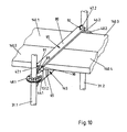
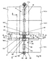
- Bridging plate 511 is provided to bridge the gap 576 between the Scaffold floors 140.1 and 140.3 on the one hand and the Console scaffolding floors 140.5 and 140.6 on the other hand. This faces the end a lift-off fixation tab 512 on the down placed under the two bridging and Lift-off protection plates 80 and 580 engage.
- the width 515 the lift fixation tab 512 is smaller and the width the bridging plate 511 is larger than that Lateral distance 514 between the scaffold floors 140.1 or 140.3 and the console scaffolding floors 140.5 and 140.6.
- the invention relates to a scaffold (30) or scaffold part with a support structure element arrangement, which has a torsionally rigid space structure with the aid of supports (31), horizontal bars (35, 36, 45) and Forms diagonal bars (37), and module grid dimensions in all three spatial directions and longitudinal connection grid dimensions for standard connecting scaffold floors (40.1 to 40.4).
- Horizontal support elements or Support bar (45) is connected by means of a wedge (47) via wedge heads (46), which are plugged onto horizontally attached perforated disks (48) of the stems (31).
- the scaffold floors (40) are open Horizontal support elements or support bolts (45) are at least partially secured against displacement by means of securing pins attached to them and supported against being lifted off.
Landscapes
- Engineering & Computer Science (AREA)
- Architecture (AREA)
- Mechanical Engineering (AREA)
- Civil Engineering (AREA)
- Structural Engineering (AREA)
- Bridges Or Land Bridges (AREA)
- Movable Scaffolding (AREA)
- Glass Compositions (AREA)
- Transition And Organic Metals Composition Catalysts For Addition Polymerization (AREA)
- Control Of Motors That Do Not Use Commutators (AREA)
Claims (20)
- Echafaudage (30) avec un ensemble d'éléments de structure porteuse, avec lequel une structure porteuse à trois dimensions rigide à la torsion est formée à l'aide de montants (31), de barres horizontales (35, 36, 45) et de barres en diagonale (37), l'échafaudage (30) ayant des dimensions modulaires dans les trois directions spatiales ainsi que des dimensions modulaires de raccordement longitudinal pour les plateaux d'échafaudage (40, 140, 240, 339, 340) et avec lequel la dimension modulaire en largeur est choisie en fonction de la largeur de l'espace de travail du personnel et la dimension modulaire en hauteur correspond à une dimension de module de hauteur pour une répartition variable d'une hauteur de travail d'une personne tandis que la dimension modulaire en longueur correspond à l'extension horizontale d'une dimension de champ et les dimensions modulaires de raccordement longitudinal selon la conception des éléments d'appui sont plus petites que les dimensions modulaires en longueur, avec les caractéristiques suivantes :a. des verrous porteurs horizontaux (45, 145, 245, 345, 444, 445) appuyés sur les montants (31) sont raccordés à des éléments nodaux chacun à l'aide d'une clavette ;b. les plateaux d'échafaudage (40, 140, 240, 339, 340; 140.5, 140.6) sont appuyés sur les verrous porteurs horizontaux (45, 145, 245, 345, 444, 445) ;c. des moyens d'appui des plateaux et des moyens d'appui des verrous sont prévus pour l'appui des plateaux d'échafaudage (40, 140, 240, 339, 340 ; 140.5, 140.6), sur les verrous porteurs horizontaux (45, 145, 245, 345, 444, 445) ;d. les plateaux d'échafaudage (40, 140, 240, 339, 340 ; 140.5, 140.6) sont protégés contre le soulèvement et sont au moins partiellement protégés contre le coulissement ;e. les verrous porteurs horizontaux (45, 145, 245, 345, 444, 445) sont munis à leurs extrémités ou à l'une de leurs extrémités de têtes de clavettes (46) avec des fentes horizontales (24) se trouvant approximativement à mi-hauteur pour l'enfichage sur des disques perforés (48), disposés horizontalement, des montants (31) et pour le passage des clavettes (47) à travers les pièces de tête (19, 20) se trouvant au-dessus et en dessous du disque perforé associé (48) et à travers les trous dans les disques perforés (48) qui évitent, en l'absence de toute intervention manuelle, un dégagement réciproque des éléments lorsque les clavettes (47) sont enfichées ;f. les plateaux d'échafaudage sont munis au moins partiellement dans la zone de leurs extrémités frontales de trous d'arrêt (57) cylindriques s'étendant verticalement ;g. sur les verrous porteurs horizontaux (45, 145, 245, 345, 444, 445) sont disposées des broches verticales (65) ayant des dimensions adaptées aux trous d'arrêt (57) ;h. les broches verticales (65) sont disposées conformément à l'espacement des trous et à l'espacement des surfaces terminales par rapport aux trous d'arrêt (57) prévus dans les plateaux d'échafaudage (40, 140, 240, 340 ; 140.5, 140.6) et dépassent par-dessus une surface d'appui de verrou supérieure du verrou porteur horizontal (45, 145, 245, 345, 444, 445) ;i. les broches verticales (65) dépassent avec une longueur de logement libre (67) par-dessus la surface d'appui de verrou, qui est un peu plus petite que ou au plus égale à l'épaisseur du plateau d'échafaudage (40, 140, 240, 340 ; 140.5, 140.6) et/ou de sa zone d'appui ;j. les bords des trous des plateaux d'échafaudage (40, 140, 240, 340 ; 140.5, 140.6) sont conçus comme surfaces d'appui des plateaux pour un appui sur la surface d'appui de verrou, caractérisé par les caractéristiques suivantes :k. les trous d'arrêt (57) sont munis de douilles verticales traversantes (58), dans lesquelles peuvent être introduites de manière relativement précise les broches verticales (65) ;l. le verrou porteur horizontal (45, 145, 245, 345, 444, 445) comprend des espaces libres d'engagement (97) pour la réception d'au moins un moyen de protection contre le soulèvement (95 ; 595) recouvrant les extrémités des plateaux d'échafaudage (40, 140, 240, 339, 340 ; 140.5, 140.6).
- Echafaudage selon la revendication 1, caractérisé en ce que le moyen de protection contre le soulèvement (95 ; 595) est conçu avec une plaque de pontage et de protection contre le soulèvement (80 ; 580), qui est munie sur le côté inférieur de pièces d'espacement verticales ainsi que d'éléments de branches horizontales d'appui et de fixation.
- Echafaudage selon au moins l'une quelconque des revendications 1 ou 2, caractérisé en ce que le moyen de protection contre le soulèvement (95 ; 595) est muni de crochets d'arrêt (85 ; 585) et d'une trappe d'arrêt se trouvant du côté terminal (89 ; 589).
- Echafaudage selon la revendication 2 ou 3, caractérisé en ce que les éléments de branches d'appui et de fixation sont formés avec au moins une broche de protection contre le coulissement (96) s'étendant sensiblement horizontalement et perpendiculairement à l'axe longitudinal du verrou porteur horizontal (45) et pénétrant dans une ouverture d'engagement (97), ouverte en haut et en forme de crochet, du verrou porteur horizontal (45) ou de l'élément de support horizontal (501).
- Echafaudage selon au moins l'une quelconque des revendications 1 à 4, caractérisé en ce que le verrou porteur horizontal (245) est formé avec une surface d'appui (262) se trouvant approximativement à la hauteur de la surface de circulation (69).
- Echafaudage selon la revendication 5, caractérisé en ce que la plaque de pontage et de protection contre le soulèvement (80 ; 580) est une mince plaque de tôle ou réalisée en coulée continue, qui s'appuie sur la surface d'appui (262) dans des zones de surfaces au moins plus importantes et qui est munie de crochets d'arrêt (85 ; 585) pour l'accrochage et la fixation.
- Echafaudage selon au moins l'une quelconque des revendications 1 à 6, caractérisé en ce que le verrou porteur horizontal (45, 145, 245, 345, 444, 445) comprend au moins une paroi porte-broches verticale (51, 151, 449, 451 ; 551), sur laquelle sont fixées les broches verticales (65).
- Echafaudage selon au moins l'une quelconque des revendications 1 à 7, caractérisé en ce que les brochés verticales (65) sont disposées sur les deux côtés du verrou porteur horizontal (45, 145, 245, 444, 445).
- Echafaudage selon la revendication 7 ou 8, caractérisé en ce que les broches verticales (65) dépassent au moins partiellement par-dessus la paroi porte-broches (51, 151, 449, 451 ; 551).
- Echafaudage selon au moins l'une quelconque des revendications 1 à 9, caractérisé en ce que le verrou porteur horizontal (45, 145, 245, 345, 444, 445) est conçu avec un tube support de verrou horizontal (53, 153, 253, 353, 423, 453) qui comprend sur son côté inférieur au moins un orifice d'écoulement (84, 184 ; 584) pour des matières fluides.
- Echafaudage selon au moins l'une quelconque des revendications 1 à 10, caractérisé en ce que les moyens d'appui de plateaux comprennent sur au moins une partie des plateaux d'échafaudage (340), dans la zone de leurs extrémités frontales, des trous d'arrêt (57) s'étendant dans le sens vertical, alors que dans une autre partie des plateaux d'échafaudage (339), dans la zone de leurs extrémités frontales, ils comprennent des griffes (343).
- Echafaudage selon au moins l'une quelconque des revendications 1 à 11, caractérisé en ce que les moyens d'appui des verrous sont conçus sur un côté du verrou porteur horizontal (345) avec des broches verticales (65) ayant des dimensions adaptées aux trous d'arrêt (57) ainsi qu'avec des surfaces d'appui de verrou (361) pour des plateaux d'échafaudage (340) avec des trous d'arrêt (57), alors que sur un autre côté du verrou porteur horizontal (345) les moyens d'appui de verrou comprennent des surfaces d'appui de verrou (341) pour des plateaux d'échafaudage (339) avec des griffes (343).
- Echafaudage selon la revendication 12, caractérisé en ce que les hauteurs des deux surfaces d'appui de verrou (341, 361) sont ajustées de telle manière entre elles que les surfaces de circulation des plateaux d'échafaudage (339) comprenant des griffes et les surfaces de circulation des plateaux d'échafaudage (340) comprenant des trous d'arrêt soient situées approximativement au même niveau.
- Echafaudage selon au moins l'une quelconque des revendications 2 à 6, caractérisé en ce que, sur le côté s'écartant de la trappe d'arrêt (589), la plaque de pontage et de protection contre le soulèvement (580) comprend une languette de butée (520) disposée à peu près normalement par rapport au plan de la plaque.
- Echafaudage selon au moins l'une quelconque des revendications 2 à 6, caractérisé en ce que, sur le côté s'écartant de la trappe d'arrêt (589), le moyen de protection contre le soulèvement (595) comprend une disposition à double nervure (598) s'étendant normalement par rapport au plan de la plaque, l'espacement entre les nervures correspondant approximativement au diamètre du montant (31) (figure 19).
- Echafaudage selon au moins l'une quelconque des revendications 1 à 15, caractérisé en ce que pour le pontage de la fente entre les plateaux d'échafaudage à consoles (140.5 et 140.6) et les autres plateaux d'échafaudage situés à l'opposé (140.1 et 140.3) il est prévu un moyen de pontage (510) formé avec une plaque de pontage (511).
- Echafaudage selon la revendication 16, caractérisé en ce que le moyen de pontage (510) est conçu avec une languette de fixation contre le soulèvement (512), qui pénètre d'une part sous la plaque de fixation contre le soulèvement (580) du moyen de fixation contre le soulèvement (595) et d'autre part sous la plaque de fixation contre le soulèvement (80) du moyen de fixation contre le soulèvement (95).
- Echafaudage selon la revendication 17, caractérisé en ce que le moyen de pontage (510) est protégé contre le coulissement latéral à l'aide de la languette de fixation contre le soulèvement (512) prévue de manière ajustée entre les surfaces frontales latérales dirigées l'une vers l'autre des plateaux d'échafaudage à consoles (140.5 et 140.6) et les autres plateaux d'échafaudage situés à l'opposé (140.1 et 140.3).
- Echafaudage selon au moins l'une quelconque des revendications 1 à 18, caractérisé en ce que l'appui des extrémités de plateaux d'échafaudage associées à une paire de montants (31.1 ; 31.2) et se trouvant des deux côtés du plan vertical commun aux deux montants est espacé de telle manière (espacement 75) que l'appui sur les parties de bras en porte-à-faux fixées à l'aide de têtes de clavettes sur les disques perforés des montants de manière à éviter tout basculement conduit à une conception en forme de support de Gerber de la section d'étage respective.
- Echafaudage selon au moins l'une quelconque des revendications 1 à 19, caractérisé en ce que l'ensemble d'éléments de structure porteuse est conçu avec des consoles (500), qui comprennent respectivement au lieu du verrou porteur horizontal un élément de support horizontal (501) avec une tête de clavette (46.3) fixée à une extrémité (554.1), avec une extrémité libre (554.2), avec une jambe de force verticale (502) fixée sur l'extrémité de la tête de clavette (554.1) et s'appuyant sur le montant (31) en s'étendant à peu près perpendiculairement à l'élément de support horizontal (501) et avec une jambe de force transversale (503) conduisant de l'extrémité libre (554.2) vers la jambe de force verticale (502), ainsi qu'avec des broches verticales (65), qui sont disposées avec des dimensions adaptées aux trous d'arrêt (57) des plateaux d'échafaudage ou des plateaux d'échafaudage à consoles (140.5, 140.6).
Applications Claiming Priority (2)
| Application Number | Priority Date | Filing Date | Title |
|---|---|---|---|
| DE19511848 | 1995-03-31 | ||
| DE19511848 | 1995-03-31 |
Publications (2)
| Publication Number | Publication Date |
|---|---|
| EP0736648A1 EP0736648A1 (fr) | 1996-10-09 |
| EP0736648B1 true EP0736648B1 (fr) | 2003-07-16 |
Family
ID=7758266
Family Applications (1)
| Application Number | Title | Priority Date | Filing Date |
|---|---|---|---|
| EP96105043A Expired - Lifetime EP0736648B1 (fr) | 1995-03-31 | 1996-03-29 | Echafaudage |
Country Status (3)
| Country | Link |
|---|---|
| EP (1) | EP0736648B1 (fr) |
| AT (1) | ATE245242T1 (fr) |
| DE (2) | DE59610602D1 (fr) |
Cited By (3)
| Publication number | Priority date | Publication date | Assignee | Title |
|---|---|---|---|---|
| EP3896240A1 (fr) * | 2020-04-15 | 2021-10-20 | RUX GmbH | Échafaudage |
| EP4183951A1 (fr) | 2021-11-23 | 2023-05-24 | ALFIX GmbH | Élément de sécurité pour planchers, échafaudage et procédé pour empêcher les planchers d'échafaudage de se soulever |
| DE202023105452U1 (de) | 2023-09-19 | 2023-09-28 | Alfix Gmbh | Belagsicherungselement und Baugerüst hiermit |
Families Citing this family (3)
| Publication number | Priority date | Publication date | Assignee | Title |
|---|---|---|---|---|
| AU2013101084B4 (en) * | 2013-02-11 | 2015-02-05 | 4 Ken Pty Ltd | Method and system for oblique scaffold connection |
| US10604951B2 (en) * | 2016-11-03 | 2020-03-31 | Alum-A-Pole Corporation | Support member for joinable scaffolding planks |
| CN114541730B (zh) * | 2022-03-16 | 2023-11-28 | 山东汇扬自动化设备有限公司 | 一种安全性高的便于拆装爬架 |
Family Cites Families (7)
| Publication number | Priority date | Publication date | Assignee | Title |
|---|---|---|---|---|
| DE3020389A1 (de) * | 1980-05-29 | 1981-12-03 | geb. Layher Ruth 7129 Güglingen Langer | Abhubsicherung fuer baugerueste |
| US4340130A (en) * | 1980-07-24 | 1982-07-20 | Kwikform America, Inc. | Scaffold frame header |
| DE8513985U1 (de) * | 1985-05-11 | 1985-09-05 | Müller & Borggräfe KG, 5820 Gevelsberg | Bohlengerüst aus Vertikalrahmen und Belagtafeln |
| ES2050133T3 (es) * | 1987-09-23 | 1994-05-16 | Geb Layher Ruth Langer | Pieza angular de fondo. |
| DE3824922A1 (de) * | 1988-07-22 | 1990-01-25 | Langer Ruth Geb Layher | Holzleiterngeruest mit aufstiegseinrichtungen |
| DE9311974U1 (de) * | 1993-08-11 | 1993-09-30 | Mafisco Bautechnik GmbH, 88480 Achstetten | Gerüstelement für im Bauwesen zu verwendende Gerüstsysteme |
| DE9417096U1 (de) * | 1994-10-27 | 1995-02-23 | Günter Rux GmbH, 58135 Hagen | Standgerüstelement |
-
1996
- 1996-03-29 AT AT96105043T patent/ATE245242T1/de not_active IP Right Cessation
- 1996-03-29 EP EP96105043A patent/EP0736648B1/fr not_active Expired - Lifetime
- 1996-03-29 DE DE59610602T patent/DE59610602D1/de not_active Expired - Fee Related
- 1996-03-29 DE DE19612537A patent/DE19612537A1/de not_active Withdrawn
Cited By (4)
| Publication number | Priority date | Publication date | Assignee | Title |
|---|---|---|---|---|
| EP3896240A1 (fr) * | 2020-04-15 | 2021-10-20 | RUX GmbH | Échafaudage |
| EP4183951A1 (fr) | 2021-11-23 | 2023-05-24 | ALFIX GmbH | Élément de sécurité pour planchers, échafaudage et procédé pour empêcher les planchers d'échafaudage de se soulever |
| DE102021130655A1 (de) | 2021-11-23 | 2023-05-25 | Alfix Gmbh | Belagsicherungselement, Baugerüst und Verfahren zur Sicherung von Gerüstbelägen gegen Abheben |
| DE202023105452U1 (de) | 2023-09-19 | 2023-09-28 | Alfix Gmbh | Belagsicherungselement und Baugerüst hiermit |
Also Published As
| Publication number | Publication date |
|---|---|
| DE19612537A1 (de) | 1996-10-02 |
| DE59610602D1 (de) | 2003-08-21 |
| EP0736648A1 (fr) | 1996-10-09 |
| ATE245242T1 (de) | 2003-08-15 |
Similar Documents
| Publication | Publication Date | Title |
|---|---|---|
| DE2704398C3 (de) | Aus Ständern und Riegeln zusammensetzbares Gerüst | |
| EP0918912B1 (fr) | Echafaudage de facade demontable | |
| EP0276487B1 (fr) | Echaufaudage avec moyens de raccord | |
| EP2411598B1 (fr) | Échafaudage et procédé de montage ou de démontage d'un tel échafaudage | |
| EP2642045B1 (fr) | Agencement de recouvrement d'au moins deux planches | |
| DE3832066A1 (de) | Geruestbodenteil | |
| DE3004245C2 (de) | Deckenschalung mit Fallköpfen | |
| DE19511847A1 (de) | Tragstruktur-Element-Anordnung eines Gerüstes | |
| EP0851075B1 (fr) | Plate-forme surélevée ou charpente, plus particulièrement exécutée comme coffrage de dalles en béton | |
| EP0116679A1 (fr) | Echafaudage, notamment échafaudage pour le bâtiment | |
| EP0308882B1 (fr) | Plate-forme pour échafaudages | |
| DE19612867A1 (de) | Gerüstboden | |
| DE4027754C3 (de) | Stützausbildung für Gerüstböden o. dgl. mit wenigstens einer Aussparung in der begehbaren Fläche | |
| EP0736648B1 (fr) | Echafaudage | |
| DE3504188A1 (de) | Diagonalstrebe fuer gerueste | |
| EP4379169B1 (fr) | Système de cadre vertical pour échafaudage de système | |
| DE9409626U1 (de) | Balkonkonstruktion | |
| DE4011624A1 (de) | Geruestboden | |
| EP0268197B1 (fr) | Echafaudage, plus spécialement échafaudage pour le bâtiment | |
| EP0331796B1 (fr) | Dispositif renforcé de suspension pour câbles | |
| EP0851074B1 (fr) | Echafaudage pour plate-forme, charpente ou coffrage de dalle | |
| EP3354818B1 (fr) | Dispositif de compensation en longueur pour échafaudages | |
| EP0276486B1 (fr) | Plinthe pour échafaudage | |
| EP1134331A2 (fr) | Ensemble d'éléments pour un coffrage | |
| DE4011625A1 (de) | Auflagehaken fuer geruestboeden |
Legal Events
| Date | Code | Title | Description |
|---|---|---|---|
| PUAI | Public reference made under article 153(3) epc to a published international application that has entered the european phase |
Free format text: ORIGINAL CODE: 0009012 |
|
| AK | Designated contracting states |
Kind code of ref document: A1 Designated state(s): AT BE CH DE DK ES FI FR GB IE IT LI LU MC NL PT SE |
|
| 17P | Request for examination filed |
Effective date: 19970128 |
|
| 17Q | First examination report despatched |
Effective date: 19990705 |
|
| RAP1 | Party data changed (applicant data changed or rights of an application transferred) |
Owner name: WILHELM LAYHER VERMOEGENSVERWALTUNGS-GMBH |
|
| RIN1 | Information on inventor provided before grant (corrected) |
Inventor name: LAYHER, ULRICH |
|
| GRAH | Despatch of communication of intention to grant a patent |
Free format text: ORIGINAL CODE: EPIDOS IGRA |
|
| GRAH | Despatch of communication of intention to grant a patent |
Free format text: ORIGINAL CODE: EPIDOS IGRA |
|
| GRAA | (expected) grant |
Free format text: ORIGINAL CODE: 0009210 |
|
| AK | Designated contracting states |
Designated state(s): AT BE CH DE DK ES FI FR GB IE IT LI LU MC NL PT SE |
|
| PG25 | Lapsed in a contracting state [announced via postgrant information from national office to epo] |
Ref country code: NL Free format text: LAPSE BECAUSE OF FAILURE TO SUBMIT A TRANSLATION OF THE DESCRIPTION OR TO PAY THE FEE WITHIN THE PRESCRIBED TIME-LIMIT Effective date: 20030716 Ref country code: IT Free format text: LAPSE BECAUSE OF FAILURE TO SUBMIT A TRANSLATION OF THE DESCRIPTION OR TO PAY THE FEE WITHIN THE PRESCRIBED TIME-LIMIT;WARNING: LAPSES OF ITALIAN PATENTS WITH EFFECTIVE DATE BEFORE 2007 MAY HAVE OCCURRED AT ANY TIME BEFORE 2007. THE CORRECT EFFECTIVE DATE MAY BE DIFFERENT FROM THE ONE RECORDED. Effective date: 20030716 Ref country code: IE Free format text: LAPSE BECAUSE OF FAILURE TO SUBMIT A TRANSLATION OF THE DESCRIPTION OR TO PAY THE FEE WITHIN THE PRESCRIBED TIME-LIMIT Effective date: 20030716 Ref country code: GB Free format text: LAPSE BECAUSE OF FAILURE TO SUBMIT A TRANSLATION OF THE DESCRIPTION OR TO PAY THE FEE WITHIN THE PRESCRIBED TIME-LIMIT Effective date: 20030716 Ref country code: FR Free format text: LAPSE BECAUSE OF FAILURE TO SUBMIT A TRANSLATION OF THE DESCRIPTION OR TO PAY THE FEE WITHIN THE PRESCRIBED TIME-LIMIT Effective date: 20030716 Ref country code: FI Free format text: LAPSE BECAUSE OF FAILURE TO SUBMIT A TRANSLATION OF THE DESCRIPTION OR TO PAY THE FEE WITHIN THE PRESCRIBED TIME-LIMIT Effective date: 20030716 Ref country code: ES Free format text: LAPSE BECAUSE OF FAILURE TO SUBMIT A TRANSLATION OF THE DESCRIPTION OR TO PAY THE FEE WITHIN THE PRESCRIBED TIME-LIMIT Effective date: 20030716 |
|
| REG | Reference to a national code |
Ref country code: GB Ref legal event code: FG4D Free format text: NOT ENGLISH |
|
| REG | Reference to a national code |
Ref country code: CH Ref legal event code: EP |
|
| REG | Reference to a national code |
Ref country code: IE Ref legal event code: FG4D Free format text: GERMAN |
|
| REF | Corresponds to: |
Ref document number: 59610602 Country of ref document: DE Date of ref document: 20030821 Kind code of ref document: P |
|
| PG25 | Lapsed in a contracting state [announced via postgrant information from national office to epo] |
Ref country code: SE Free format text: LAPSE BECAUSE OF FAILURE TO SUBMIT A TRANSLATION OF THE DESCRIPTION OR TO PAY THE FEE WITHIN THE PRESCRIBED TIME-LIMIT Effective date: 20031016 Ref country code: DK Free format text: LAPSE BECAUSE OF FAILURE TO SUBMIT A TRANSLATION OF THE DESCRIPTION OR TO PAY THE FEE WITHIN THE PRESCRIBED TIME-LIMIT Effective date: 20031016 |
|
| NLV1 | Nl: lapsed or annulled due to failure to fulfill the requirements of art. 29p and 29m of the patents act | ||
| PG25 | Lapsed in a contracting state [announced via postgrant information from national office to epo] |
Ref country code: PT Free format text: LAPSE BECAUSE OF FAILURE TO SUBMIT A TRANSLATION OF THE DESCRIPTION OR TO PAY THE FEE WITHIN THE PRESCRIBED TIME-LIMIT Effective date: 20031216 |
|
| GBV | Gb: ep patent (uk) treated as always having been void in accordance with gb section 77(7)/1977 [no translation filed] |
Effective date: 20030716 |
|
| REG | Reference to a national code |
Ref country code: IE Ref legal event code: FD4D |
|
| PG25 | Lapsed in a contracting state [announced via postgrant information from national office to epo] |
Ref country code: LU Free format text: LAPSE BECAUSE OF NON-PAYMENT OF DUE FEES Effective date: 20040329 Ref country code: AT Free format text: LAPSE BECAUSE OF NON-PAYMENT OF DUE FEES Effective date: 20040329 |
|
| PG25 | Lapsed in a contracting state [announced via postgrant information from national office to epo] |
Ref country code: MC Free format text: LAPSE BECAUSE OF NON-PAYMENT OF DUE FEES Effective date: 20040331 Ref country code: LI Free format text: LAPSE BECAUSE OF NON-PAYMENT OF DUE FEES Effective date: 20040331 Ref country code: CH Free format text: LAPSE BECAUSE OF NON-PAYMENT OF DUE FEES Effective date: 20040331 Ref country code: BE Free format text: LAPSE BECAUSE OF NON-PAYMENT OF DUE FEES Effective date: 20040331 |
|
| PLBE | No opposition filed within time limit |
Free format text: ORIGINAL CODE: 0009261 |
|
| STAA | Information on the status of an ep patent application or granted ep patent |
Free format text: STATUS: NO OPPOSITION FILED WITHIN TIME LIMIT |
|
| 26N | No opposition filed |
Effective date: 20040419 |
|
| EN | Fr: translation not filed | ||
| BERE | Be: lapsed |
Owner name: WILHELM *LAYHER VERMOGENSVERWALTUNGS-G.M.B.H. Effective date: 20040331 |
|
| REG | Reference to a national code |
Ref country code: CH Ref legal event code: PL |
|
| PGFP | Annual fee paid to national office [announced via postgrant information from national office to epo] |
Ref country code: DE Payment date: 20050425 Year of fee payment: 10 |
|
| PG25 | Lapsed in a contracting state [announced via postgrant information from national office to epo] |
Ref country code: DE Free format text: LAPSE BECAUSE OF NON-PAYMENT OF DUE FEES Effective date: 20061003 |