EP0126438A2 - Seitentürscharniermechanismus eines Kraftfahrzeugs - Google Patents
Seitentürscharniermechanismus eines Kraftfahrzeugs Download PDFInfo
- Publication number
- EP0126438A2 EP0126438A2 EP84105619A EP84105619A EP0126438A2 EP 0126438 A2 EP0126438 A2 EP 0126438A2 EP 84105619 A EP84105619 A EP 84105619A EP 84105619 A EP84105619 A EP 84105619A EP 0126438 A2 EP0126438 A2 EP 0126438A2
- Authority
- EP
- European Patent Office
- Prior art keywords
- side door
- disposed
- rotary link
- points
- rotary
- Prior art date
- Legal status (The legal status is an assumption and is not a legal conclusion. Google has not performed a legal analysis and makes no representation as to the accuracy of the status listed.)
- Granted
Links
Images
Classifications
-
- E—FIXED CONSTRUCTIONS
- E05—LOCKS; KEYS; WINDOW OR DOOR FITTINGS; SAFES
- E05D—HINGES OR SUSPENSION DEVICES FOR DOORS, WINDOWS OR WINGS
- E05D3/00—Hinges with pins
- E05D3/06—Hinges with pins with two or more pins
- E05D3/14—Hinges with pins with two or more pins with four parallel pins and two arms
- E05D3/145—Hinges with pins with two or more pins with four parallel pins and two arms specially adapted for vehicles
- E05D3/147—Hinges with pins with two or more pins with four parallel pins and two arms specially adapted for vehicles for vehicle doors
-
- E—FIXED CONSTRUCTIONS
- E05—LOCKS; KEYS; WINDOW OR DOOR FITTINGS; SAFES
- E05D—HINGES OR SUSPENSION DEVICES FOR DOORS, WINDOWS OR WINGS
- E05D15/00—Suspension arrangements for wings
- E05D15/04—Suspension arrangements for wings with arms fixed on the wing pivoting about an axis outside of the wing
-
- E—FIXED CONSTRUCTIONS
- E05—LOCKS; KEYS; WINDOW OR DOOR FITTINGS; SAFES
- E05D—HINGES OR SUSPENSION DEVICES FOR DOORS, WINDOWS OR WINGS
- E05D15/00—Suspension arrangements for wings
- E05D15/28—Suspension arrangements for wings supported on arms movable in horizontal plane
-
- E—FIXED CONSTRUCTIONS
- E05—LOCKS; KEYS; WINDOW OR DOOR FITTINGS; SAFES
- E05D—HINGES OR SUSPENSION DEVICES FOR DOORS, WINDOWS OR WINGS
- E05D15/00—Suspension arrangements for wings
- E05D15/28—Suspension arrangements for wings supported on arms movable in horizontal plane
- E05D15/32—Suspension arrangements for wings supported on arms movable in horizontal plane with two pairs of pivoted arms
-
- E—FIXED CONSTRUCTIONS
- E05—LOCKS; KEYS; WINDOW OR DOOR FITTINGS; SAFES
- E05Y—INDEXING SCHEME ASSOCIATED WITH SUBCLASSES E05D AND E05F, RELATING TO CONSTRUCTION ELEMENTS, ELECTRIC CONTROL, POWER SUPPLY, POWER SIGNAL OR TRANSMISSION, USER INTERFACES, MOUNTING OR COUPLING, DETAILS, ACCESSORIES, AUXILIARY OPERATIONS NOT OTHERWISE PROVIDED FOR, APPLICATION THEREOF
- E05Y2900/00—Application of doors, windows, wings or fittings thereof
- E05Y2900/50—Application of doors, windows, wings or fittings thereof for vehicles
- E05Y2900/53—Type of wing
- E05Y2900/531—Doors
Definitions
- This invention relates to a side door hinge mechanism in a motor vehicle, in which a quadric crank chain mechanism is utilized.
- the side door in a motor vehicle e.g. passenger car has heretofore been installed in a manner to be rotatable about a hinge affixed to a vehicle body for opening or closing.
- a door opening angle corresponding to the total length of the side door is required.
- one of the aforesaid front rotary link is formed by interconnecting two points including the front end point of the side door, possibly the foremost point, and a point forwardly of the front pillar, so that the side door is slidable forwardly to a considerable extent.
- the primary object of the present invention is to provide a side door hinge mechanism in a motor vehicle, capable of allowing an occupant of a vehicle to easily get on or off the vehicle by opening a side door even when a space at the side of the vehicle is small.
- the present invention has as its secondary object the provision of a quadric crank chain type side door hinge mechanism capable of allowing the occupant to further easily get on or off the vehicle in a side door opened state.
- the present invention has as its object the provision of a side door hinge mechanism in a motor vehicle, utilizing a quadric crank chain, in which the front rotary link is formed by interconnecting two points including the front end point of the side door and a point forwardly of the front pillar, without curving the rotary link, designing the side door into an unusual shape or increasing the weight and the area of the side door.
- a quadric crank chain comprises: a front rotary link interconnecting two points which are disposed at the front side of a vehicle body and a side door as rotary shafts out of four points including two points disposed on the vehicle body and spaced apart from each other in the longitudinal direction of the vehicle body and two points disposed on the side door and spaced apart from each other in the longitudinal direction of the side door, a rear rotary link interconnecting two points disposed at the rear sides as rotary shafts, a portion between the two points on the vehicle body, and a portion between the two points on the side door; the rotary shaft at the front side of the vehicle body is disposed forwardly of the rear end of a front fender and inwardly of the front fender, a portion of the front fender, which covers the outer surface of the aforesaid front rotary link, is divided from a main body of the front fender to be formed into a
- the present invention contemplates that the rotary shaft of the aforesaid front rotary link on the side door is disposed at a position close to the forward end portion of the side door, whereby the front rotary link is disposed at a position where it does not hinder the occupant from getting on or off the vehicle.
- the present invention contemplates that said rotary shaft of the front rotary link on the side door is disposed on an end panel at the forward end portion of said side door.
- the present invention contemplates that the rotary shaft of the rear rotary link on the vehicle body is disposed at a position close to the rear end of a front pillar, whereby the rear rotary link is disposed at a forward position where it does not hinder the occupant from getting on or off the vehicle.
- said movable fender comprises a portion of said front fender, said portion being disposed rearwardly of a front wheel and generally being lower than at least said front rotary link.
- said front rotary link is disposed at the lower portion of said side door and rearwardly of a front wheel.
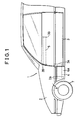
- a quadric crank chain comprises: a front rotary link 4 interconnecting two points which are disposed at the forward sides of a vehicle body 2 and a side door 3 in a motor vehicle 1 as rotary shafts 2A and 3A out of four points including two points disposed on the vehicle body 2 and spaced apart from each other in the longitudinal direction of the vheicle body.2 and two points disposed on the side door 3 and spaced apart from each other in the longitudinal direction of the side door 3; a rear rotary link 5 interconnecting two points disposed at the rear sides as rotary shafts 2B and 3B; a portion between the two points on the vehicle body 2; and a portion between the two points on the side door 3, whereby a side door hinge mechanism in a motor vheicle is formed.
- the respective rotary shafts 2A, 2B, 3A and 3B are elongated in the vertical direction of the vehicle body, and the front rotary link 4 and the rear rotary link 5 and formed to have large widths in the vertical dirction, corresponding to the lengths of these rotary shafts, respectively.
- the front rotary link 4 and the rear rotary link 5 control a moving path of the side door 3 during its opening or closing, and support the weight of the side door 3 as well.
- the front rotary shaft 2A on the vehicle body 2 is disposed forwardly of the rear end of a front fender 6 and inwardly of the front fender 6, and a portion of the front fender 6, which covers the outer surface of the front rotary link 4, is divided from a main body of the front fender 6 to be formed into a movable fender 6A rotatable with the front rotary link 4.
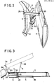
- this movable fender 6A as centered about the rotary shaft 6A is provided rearwardly of a moving path of a front wheel 7 as shown in Fig. 3, whereby, the movable fender 6A does not interfere with the front wheel 7.
- the rotary shaft 3A of the front rotary link 4 on the side door 3 is disposed at a position close to the forward end portion of the side door 3, e.g. on a front end panel 9, and the rotary shaft 2B of the rear rotary link 5 on the vehicle body 2 is disposed at a position close to the rear end of a front pillar 8.
- the rotary shaft 3B of the rear rotary link 5 on the side door 3 is disposed at a position inwardly of the substantially central portion in the longitudinal direction of the side door 3.
- the front rotary link 4 is made to be shorter in length than the rear rotry link 5, so that the rear portion of the side door 3 can be opened wider than the forward portion thereof in a fully opened state of the side door 3 as indicated by two-dot chain lines in Fig. 3.
- Reference numeral 5A designates a cover of the rotary link 5.
- the side door 3 is opened or closed by the quadric crank chain mechanism, so that, even when a space at the side of the motor vehicle 1 is small, an opening for allowing the occupant to get on or off the vehicle can be obtained without making the side door 3 to greatly project sidewards.
- a portion of the front fender 6 is formed into the movable fender 6A and this movable fender 6A is made rotatable with the front rotary link 4, whereby the front rotary link 4 and the rotary shaft 2A thereof can be disposed frowardly, so that, when the side door-3 is opened, a forwardly movement value of the side door 3 can be increased to provide a sufficient opening for allowing the occupant to get on or off the vehicle.
- the two rotary links 4 and 5 when the side door 3 is opened or closed by the quadric crank chain mechanism as described above, the two rotary links 4 and 5 must support not only the weight of the side door 3 but also the side door 3 against an angular moment of the side door 3 in the direction of thickness thereof. For this purpose, it is desirable that the two rotary links 4 and 5 be offset in the vertical direction.
- the front rotary link 4 and the rear rotary link 5 are offset in the vertical direction, it is desirable that at least a portion of the front rotary link 4 be positioned forwardly of the front pillar 8. In order to prevent the front rotarty link 4 from interfering with the front fender 6 at this time, it is necessary to mount the front rotary link 4 onto the undersurface of a floor of the motor vehicle 1.
- the front rotary link 4 supports the weight of the side door 3 in cooperation with the rear rotary link 5, whereby the front rotary link 4 is increased in width in the vertical direction.
- the front rotary link 4 is mounted onto the undersurface of the floor of the motor vehicle 1, such a disadvantage is presented that a projection value of the front rotary link 4 projecting downwardly is considerably increased.
- a portion of the front fender 6 is formed into the movable fender 6A and the front rotary link 4 is disposed inwardly of the movable fender 6A, so that the aforesaid disadvantage can be obviated.
- the rotary shaft 2B of the front rotary link 4 on the side door 3 is disposed at a position close to the forward end portion of the side door 3, so that the front rotary link 4 can be desirably set in its mounted position in the vertical direction with the front rotary link 4 not interfering with the front pillar 8.
- the rotary shaft 2B of the rear rotary link 5 on the vehicle body 2 is disposed at a position close to the rear end of the front pillar 8, so that, when the side door 3 is opened, the rear rotary link 5 can stay at a position least hindering the occupant from getting on or off the vehicle.
- the weight of the side door 3 is supported by the front rotary link 4 and the rear rotary link 5.
- the two rotary links 4 and 5 merely control the moving path of the side door 3, and consequently, the weight of the side door 3 may be supported by a member other than these rotary links 4 and 5.
Landscapes
- Engineering & Computer Science (AREA)
- Mechanical Engineering (AREA)
- Hinges (AREA)
- Body Structure For Vehicles (AREA)
Applications Claiming Priority (2)
| Application Number | Priority Date | Filing Date | Title |
|---|---|---|---|
| JP74913/83U | 1983-05-19 | ||
| JP1983074913U JPS59179974U (ja) | 1983-05-19 | 1983-05-19 | 自動車のサイドドアヒンジ |
Publications (3)
| Publication Number | Publication Date |
|---|---|
| EP0126438A2 true EP0126438A2 (de) | 1984-11-28 |
| EP0126438A3 EP0126438A3 (en) | 1985-12-27 |
| EP0126438B1 EP0126438B1 (de) | 1989-08-16 |
Family
ID=13561098
Family Applications (1)
| Application Number | Title | Priority Date | Filing Date |
|---|---|---|---|
| EP84105619A Expired EP0126438B1 (de) | 1983-05-19 | 1984-05-17 | Seitentürscharniermechanismus eines Kraftfahrzeugs |
Country Status (4)
| Country | Link |
|---|---|
| US (1) | US4650241A (de) |
| EP (1) | EP0126438B1 (de) |
| JP (1) | JPS59179974U (de) |
| DE (1) | DE3479433D1 (de) |
Cited By (8)
| Publication number | Priority date | Publication date | Assignee | Title |
|---|---|---|---|---|
| DE3528817A1 (de) * | 1985-08-10 | 1987-02-19 | Audi Ag | Scharnier fuer fahrzeugtueren |
| US4700983A (en) * | 1984-11-02 | 1987-10-20 | Toyota Jidosha Kabushiki Kaisha | Construction of body of motor vehicle |
| US4700984A (en) * | 1984-11-02 | 1987-10-20 | Toyota Jidosha Kabushiki Kaisha | Construction of body of motor vehicle |
| US4713862A (en) * | 1984-11-02 | 1987-12-22 | Toyota Jidosha Kabushiki Kaisha | Side door hinge mechanism in motor vehicle |
| US4716623A (en) * | 1984-11-02 | 1988-01-05 | Toyota Jidosha Kabushiki Kaisha | Side door hinge mechanism in motor vehicle |
| WO1997025505A1 (en) * | 1996-01-08 | 1997-07-17 | Pentti Design | Pivot mechanism for motor car doors |
| FR2797656A1 (fr) * | 1999-08-19 | 2001-02-23 | Peugeot Citroen Automobiles Sa | Agencement d'une porte coulissante sur un vehicule |
| FR3097247A1 (fr) * | 2019-06-12 | 2020-12-18 | Renault S.A.S. | Trappe de dissimulation d’un mécanisme d’ouverture d’un ouvrant de véhicule. |
Families Citing this family (16)
| Publication number | Priority date | Publication date | Assignee | Title |
|---|---|---|---|---|
| JPH0523733Y2 (de) * | 1986-07-14 | 1993-06-17 | ||
| FR2613293B1 (fr) * | 1987-04-03 | 1992-02-07 | Matra Automobile | Dispositif de fermeture a ouvrant articule autour de deux axes |
| US6175991B1 (en) | 1998-09-14 | 2001-01-23 | Ford Global Technologies, Inc. | Articulated door hinge for an automotive vehicle |
| US6149222A (en) * | 1999-07-01 | 2000-11-21 | Daimlerchrysler Corporation | Hinge assembly for a vehicle door |
| US6305737B1 (en) | 2000-08-02 | 2001-10-23 | Asc Incorporated | Automotive vehicle door system |
| US6609748B1 (en) * | 2000-09-25 | 2003-08-26 | Ford Global Technologies, Llc | Forward facing rear door assembly for motor vehicles |
| US6799788B2 (en) * | 2002-04-08 | 2004-10-05 | Ssr Roofing Systems, Llc | Decklid mechanism for vehicle with retractable top |
| US6899368B2 (en) * | 2002-05-23 | 2005-05-31 | Wilhelm Karmann Gmbh | Decklid mechanism for vehicle with retractable top |
| CA2489097C (en) * | 2002-06-11 | 2011-06-14 | Peter Lance Oxley | Vehicle door with pivot arm |
| US6935676B2 (en) * | 2003-12-30 | 2005-08-30 | Mitsubishi Jidosha Kogyo Kabushiki Kaisha | Vehicle with door capable of swinging horizontally |
| CA2510413A1 (en) * | 2004-06-28 | 2005-12-28 | Guy Valois | Automated system for opening car doors |
| US7488029B2 (en) * | 2005-12-16 | 2009-02-10 | Ford Global Technologies, Llc | Independently opening doors for an automotive door opening |
| US7328932B2 (en) * | 2005-12-22 | 2008-02-12 | Nissan Design America, Inc. | Automotive door hinge |
| DE102007006360A1 (de) * | 2007-02-08 | 2008-08-21 | Dura Automotive Body & Glass Systems Gmbh | Schiebetüre für ein Kraftfahrzeug |
| US9303437B1 (en) * | 2014-09-16 | 2016-04-05 | Ford Global Technologies, Llc | Closure assembly incorporating an integrated articulating closure hinge and cover |
| JP7600803B2 (ja) * | 2021-03-19 | 2024-12-17 | 株式会社アイシン | 車両用ドア装置 |
Family Cites Families (8)
| Publication number | Priority date | Publication date | Assignee | Title |
|---|---|---|---|---|
| US3006683A (en) * | 1958-07-30 | 1961-10-31 | Ford Motor Co | Vehicle door hinge |
| US2956836A (en) * | 1958-09-09 | 1960-10-18 | Rolf E James | Door construction for vehicles and the like |
| US2955871A (en) * | 1959-09-17 | 1960-10-11 | Gen Motors Corp | Flipper finger guard |
| US3074755A (en) * | 1960-02-05 | 1963-01-22 | Renault | Door assembly for a vehicle |
| US3095600A (en) * | 1960-03-18 | 1963-07-02 | Gen Motors Corp | Door hinging arrangement for vehicle bodies |
| FR1331484A (fr) * | 1962-05-22 | 1963-07-05 | Dispositif de télécommande pneumatique, notamment pour attelages automatiques de véhicules de chemins de fer | |
| US3275370A (en) * | 1964-05-18 | 1966-09-27 | Ford Motor Co | Motor vehicle |
| DE2105659A1 (de) * | 1971-02-06 | 1972-08-10 | Volkswagenwerk Ag, 3180 Wolfsburg | Türanordnung fur Fahrzeuge, ins besondere Kraftfahrzeuge |
-
1983
- 1983-05-19 JP JP1983074913U patent/JPS59179974U/ja active Granted
-
1984
- 1984-05-17 DE DE8484105619T patent/DE3479433D1/de not_active Expired
- 1984-05-17 EP EP84105619A patent/EP0126438B1/de not_active Expired
- 1984-05-17 US US06/611,216 patent/US4650241A/en not_active Expired - Fee Related
Cited By (10)
| Publication number | Priority date | Publication date | Assignee | Title |
|---|---|---|---|---|
| US4700983A (en) * | 1984-11-02 | 1987-10-20 | Toyota Jidosha Kabushiki Kaisha | Construction of body of motor vehicle |
| US4700984A (en) * | 1984-11-02 | 1987-10-20 | Toyota Jidosha Kabushiki Kaisha | Construction of body of motor vehicle |
| US4713862A (en) * | 1984-11-02 | 1987-12-22 | Toyota Jidosha Kabushiki Kaisha | Side door hinge mechanism in motor vehicle |
| US4716623A (en) * | 1984-11-02 | 1988-01-05 | Toyota Jidosha Kabushiki Kaisha | Side door hinge mechanism in motor vehicle |
| DE3528817A1 (de) * | 1985-08-10 | 1987-02-19 | Audi Ag | Scharnier fuer fahrzeugtueren |
| WO1997025505A1 (en) * | 1996-01-08 | 1997-07-17 | Pentti Design | Pivot mechanism for motor car doors |
| AU715728B2 (en) * | 1996-01-08 | 2000-02-10 | Filepost Limited | Pivot mechanism for motor car doors |
| US6030025A (en) * | 1996-01-08 | 2000-02-29 | Filepost Limited | Pivot mechanism for motor car doors |
| FR2797656A1 (fr) * | 1999-08-19 | 2001-02-23 | Peugeot Citroen Automobiles Sa | Agencement d'une porte coulissante sur un vehicule |
| FR3097247A1 (fr) * | 2019-06-12 | 2020-12-18 | Renault S.A.S. | Trappe de dissimulation d’un mécanisme d’ouverture d’un ouvrant de véhicule. |
Also Published As
| Publication number | Publication date |
|---|---|
| JPH0335830Y2 (de) | 1991-07-30 |
| JPS59179974U (ja) | 1984-12-01 |
| US4650241A (en) | 1987-03-17 |
| EP0126438B1 (de) | 1989-08-16 |
| EP0126438A3 (en) | 1985-12-27 |
| DE3479433D1 (de) | 1989-09-28 |
Similar Documents
| Publication | Publication Date | Title |
|---|---|---|
| EP0126438A2 (de) | Seitentürscharniermechanismus eines Kraftfahrzeugs | |
| EP0302499B1 (de) | Bewegbarer Verkleidungsdeckel | |
| US5273310A (en) | Instrument panel structure for automotive vehicle | |
| EP0136714A2 (de) | Scharniermechanismus für Seitentüren von Kraftfahrzeugen | |
| US5491875A (en) | Extended cab pickup truck concealed cargo door hinge | |
| EP0644104A2 (de) | Fahrzeug-Motorhauben | |
| US4632447A (en) | Side door hinge mechanism in a motor vehicle | |
| EP0135929A2 (de) | Bedrahtungsaufbau in Kraftfahrzeugseitentüren | |
| EP0140245B1 (de) | Seitentürscharniermechanismus eines Kraftfahrzeugs | |
| US5244247A (en) | Door installation arrangement for vehicle | |
| US4069550A (en) | Closure panel hinge | |
| EP0125703B1 (de) | Seitentürscharniermechanismus eines Kraftfahrzeugs | |
| EP0129067B1 (de) | Aufbau eines Schmutzfängers für einen beweglichen Kotflügelteil an Motorfahrzeugen | |
| GB1566587A (en) | Motor vehicle body with a rigid sunshine roof | |
| US6257650B1 (en) | Automobile provided with movable roof | |
| GB2248875A (en) | Hinge mechanism | |
| US3147994A (en) | Swing-out vehicle seat | |
| EP0131303B1 (de) | Bauart einer Abdeckung zum Schutz gegen Vereisung eines beweglichen Kotflügelteiles von einem Kraftfahrzeug | |
| JPH01186427A (ja) | 自動車のサンルーフ構造 | |
| EP0507486A1 (de) | Ausstellbares Dachteil eines Kraftfahrzeuges | |
| KR200143354Y1 (ko) | 자동차의 2단링크형 본네트 힌지 | |
| JP2539910Y2 (ja) | 車両のルーフ構造 | |
| JPH0628972B2 (ja) | 自動車のル−フ構造 | |
| JPS6332526Y2 (de) | ||
| KR200162235Y1 (ko) | 자동차용 도어의 힌지 마운팅구조 |
Legal Events
| Date | Code | Title | Description |
|---|---|---|---|
| PUAI | Public reference made under article 153(3) epc to a published international application that has entered the european phase |
Free format text: ORIGINAL CODE: 0009012 |
|
| AK | Designated contracting states |
Designated state(s): DE FR GB |
|
| 17P | Request for examination filed |
Effective date: 19850513 |
|
| PUAL | Search report despatched |
Free format text: ORIGINAL CODE: 0009013 |
|
| AK | Designated contracting states |
Designated state(s): DE FR GB |
|
| 17Q | First examination report despatched |
Effective date: 19870701 |
|
| GRAA | (expected) grant |
Free format text: ORIGINAL CODE: 0009210 |
|
| AK | Designated contracting states |
Kind code of ref document: B1 Designated state(s): DE FR GB |
|
| REF | Corresponds to: |
Ref document number: 3479433 Country of ref document: DE Date of ref document: 19890928 |
|
| ET | Fr: translation filed | ||
| PLBE | No opposition filed within time limit |
Free format text: ORIGINAL CODE: 0009261 |
|
| STAA | Information on the status of an ep patent application or granted ep patent |
Free format text: STATUS: NO OPPOSITION FILED WITHIN TIME LIMIT |
|
| 26N | No opposition filed | ||
| REG | Reference to a national code |
Ref country code: GB Ref legal event code: 746 |
|
| REG | Reference to a national code |
Ref country code: FR Ref legal event code: DL |
|
| PGFP | Annual fee paid to national office [announced via postgrant information from national office to epo] |
Ref country code: GB Payment date: 19940509 Year of fee payment: 11 |
|
| PGFP | Annual fee paid to national office [announced via postgrant information from national office to epo] |
Ref country code: FR Payment date: 19940511 Year of fee payment: 11 Ref country code: DE Payment date: 19940511 Year of fee payment: 11 |
|
| PG25 | Lapsed in a contracting state [announced via postgrant information from national office to epo] |
Ref country code: GB Effective date: 19950517 |
|
| GBPC | Gb: european patent ceased through non-payment of renewal fee |
Effective date: 19950517 |
|
| PG25 | Lapsed in a contracting state [announced via postgrant information from national office to epo] |
Ref country code: DE Effective date: 19960201 |
|
| PG25 | Lapsed in a contracting state [announced via postgrant information from national office to epo] |
Ref country code: FR Effective date: 19960229 |
|
| REG | Reference to a national code |
Ref country code: FR Ref legal event code: ST |
|
| REG | Reference to a national code |
Ref country code: FR Ref legal event code: ST |