EP0126457A2 - Vorrichtung zum automatischen Einfügen der U-Rohre in Wärmetauscher - Google Patents
Vorrichtung zum automatischen Einfügen der U-Rohre in Wärmetauscher Download PDFInfo
- Publication number
- EP0126457A2 EP0126457A2 EP84105671A EP84105671A EP0126457A2 EP 0126457 A2 EP0126457 A2 EP 0126457A2 EP 84105671 A EP84105671 A EP 84105671A EP 84105671 A EP84105671 A EP 84105671A EP 0126457 A2 EP0126457 A2 EP 0126457A2
- Authority
- EP
- European Patent Office
- Prior art keywords
- heat transfer
- transfer tube
- tube
- gripping
- support members
- Prior art date
- Legal status (The legal status is an assumption and is not a legal conclusion. Google has not performed a legal analysis and makes no representation as to the accuracy of the status listed.)
- Granted
Links
- 238000012546 transfer Methods 0.000 claims abstract description 66
- 238000003780 insertion Methods 0.000 claims abstract description 15
- 230000037431 insertion Effects 0.000 claims abstract description 15
- 238000005406 washing Methods 0.000 claims description 31
- 238000005498 polishing Methods 0.000 claims description 24
- 239000012530 fluid Substances 0.000 claims description 21
- 230000007246 mechanism Effects 0.000 claims description 5
- 230000002093 peripheral effect Effects 0.000 claims 6
- 238000005192 partition Methods 0.000 description 25
- 210000000078 claw Anatomy 0.000 description 24
- 241000282472 Canis lupus familiaris Species 0.000 description 12
- 238000003825 pressing Methods 0.000 description 10
- 239000007788 liquid Substances 0.000 description 8
- 238000010276 construction Methods 0.000 description 4
- 239000011295 pitch Substances 0.000 description 3
- 230000000694 effects Effects 0.000 description 2
- 230000005484 gravity Effects 0.000 description 2
- 238000000034 method Methods 0.000 description 2
- 230000009471 action Effects 0.000 description 1
- 238000013459 approach Methods 0.000 description 1
- 238000004140 cleaning Methods 0.000 description 1
- 238000010586 diagram Methods 0.000 description 1
- 238000005470 impregnation Methods 0.000 description 1
- 230000006872 improvement Effects 0.000 description 1
- 238000012986 modification Methods 0.000 description 1
- 230000004048 modification Effects 0.000 description 1
- FFNMBRCFFADNAO-UHFFFAOYSA-N pirenzepine hydrochloride Chemical compound [H+].[H+].[Cl-].[Cl-].C1CN(C)CCN1CC(=O)N1C2=NC=CC=C2NC(=O)C2=CC=CC=C21 FFNMBRCFFADNAO-UHFFFAOYSA-N 0.000 description 1
- 230000008569 process Effects 0.000 description 1
- 238000003466 welding Methods 0.000 description 1
Images





Classifications
-
- B—PERFORMING OPERATIONS; TRANSPORTING
- B23—MACHINE TOOLS; METAL-WORKING NOT OTHERWISE PROVIDED FOR
- B23P—METAL-WORKING NOT OTHERWISE PROVIDED FOR; COMBINED OPERATIONS; UNIVERSAL MACHINE TOOLS
- B23P19/00—Machines for simply fitting together or separating metal parts or objects, or metal and non-metal parts, whether or not involving some deformation; Tools or devices therefor so far as not provided for in other classes
- B23P19/02—Machines for simply fitting together or separating metal parts or objects, or metal and non-metal parts, whether or not involving some deformation; Tools or devices therefor so far as not provided for in other classes for connecting objects by press fit or for detaching same
- B23P19/022—Extracting or inserting relatively long parts
-
- Y—GENERAL TAGGING OF NEW TECHNOLOGICAL DEVELOPMENTS; GENERAL TAGGING OF CROSS-SECTIONAL TECHNOLOGIES SPANNING OVER SEVERAL SECTIONS OF THE IPC; TECHNICAL SUBJECTS COVERED BY FORMER USPC CROSS-REFERENCE ART COLLECTIONS [XRACs] AND DIGESTS
- Y10—TECHNICAL SUBJECTS COVERED BY FORMER USPC
- Y10T—TECHNICAL SUBJECTS COVERED BY FORMER US CLASSIFICATION
- Y10T29/00—Metal working
- Y10T29/53—Means to assemble or disassemble
- Y10T29/53039—Means to assemble or disassemble with control means energized in response to activator stimulated by condition sensor
-
- Y—GENERAL TAGGING OF NEW TECHNOLOGICAL DEVELOPMENTS; GENERAL TAGGING OF CROSS-SECTIONAL TECHNOLOGIES SPANNING OVER SEVERAL SECTIONS OF THE IPC; TECHNICAL SUBJECTS COVERED BY FORMER USPC CROSS-REFERENCE ART COLLECTIONS [XRACs] AND DIGESTS
- Y10—TECHNICAL SUBJECTS COVERED BY FORMER USPC
- Y10T—TECHNICAL SUBJECTS COVERED BY FORMER US CLASSIFICATION
- Y10T29/00—Metal working
- Y10T29/53—Means to assemble or disassemble
- Y10T29/53039—Means to assemble or disassemble with control means energized in response to activator stimulated by condition sensor
- Y10T29/53061—Responsive to work or work-related machine element
-
- Y—GENERAL TAGGING OF NEW TECHNOLOGICAL DEVELOPMENTS; GENERAL TAGGING OF CROSS-SECTIONAL TECHNOLOGIES SPANNING OVER SEVERAL SECTIONS OF THE IPC; TECHNICAL SUBJECTS COVERED BY FORMER USPC CROSS-REFERENCE ART COLLECTIONS [XRACs] AND DIGESTS
- Y10—TECHNICAL SUBJECTS COVERED BY FORMER USPC
- Y10T—TECHNICAL SUBJECTS COVERED BY FORMER US CLASSIFICATION
- Y10T29/00—Metal working
- Y10T29/53—Means to assemble or disassemble
- Y10T29/53113—Heat exchanger
-
- Y—GENERAL TAGGING OF NEW TECHNOLOGICAL DEVELOPMENTS; GENERAL TAGGING OF CROSS-SECTIONAL TECHNOLOGIES SPANNING OVER SEVERAL SECTIONS OF THE IPC; TECHNICAL SUBJECTS COVERED BY FORMER USPC CROSS-REFERENCE ART COLLECTIONS [XRACs] AND DIGESTS
- Y10—TECHNICAL SUBJECTS COVERED BY FORMER USPC
- Y10T—TECHNICAL SUBJECTS COVERED BY FORMER US CLASSIFICATION
- Y10T29/00—Metal working
- Y10T29/53—Means to assemble or disassemble
- Y10T29/53113—Heat exchanger
- Y10T29/53117—Heat exchanger including means to manipulate heat exchanger tube bundle
-
- Y—GENERAL TAGGING OF NEW TECHNOLOGICAL DEVELOPMENTS; GENERAL TAGGING OF CROSS-SECTIONAL TECHNOLOGIES SPANNING OVER SEVERAL SECTIONS OF THE IPC; TECHNICAL SUBJECTS COVERED BY FORMER USPC CROSS-REFERENCE ART COLLECTIONS [XRACs] AND DIGESTS
- Y10—TECHNICAL SUBJECTS COVERED BY FORMER USPC
- Y10T—TECHNICAL SUBJECTS COVERED BY FORMER US CLASSIFICATION
- Y10T29/00—Metal working
- Y10T29/53—Means to assemble or disassemble
- Y10T29/53539—Means to assemble or disassemble including work conveyor
- Y10T29/53543—Means to assemble or disassemble including work conveyor including transporting track
- Y10T29/53548—Means to assemble or disassemble including work conveyor including transporting track and work carrying vehicle
-
- Y—GENERAL TAGGING OF NEW TECHNOLOGICAL DEVELOPMENTS; GENERAL TAGGING OF CROSS-SECTIONAL TECHNOLOGIES SPANNING OVER SEVERAL SECTIONS OF THE IPC; TECHNICAL SUBJECTS COVERED BY FORMER USPC CROSS-REFERENCE ART COLLECTIONS [XRACs] AND DIGESTS
- Y10—TECHNICAL SUBJECTS COVERED BY FORMER USPC
- Y10T—TECHNICAL SUBJECTS COVERED BY FORMER US CLASSIFICATION
- Y10T29/00—Metal working
- Y10T29/53—Means to assemble or disassemble
- Y10T29/53961—Means to assemble or disassemble with work-holder for assembly
-
- Y—GENERAL TAGGING OF NEW TECHNOLOGICAL DEVELOPMENTS; GENERAL TAGGING OF CROSS-SECTIONAL TECHNOLOGIES SPANNING OVER SEVERAL SECTIONS OF THE IPC; TECHNICAL SUBJECTS COVERED BY FORMER USPC CROSS-REFERENCE ART COLLECTIONS [XRACs] AND DIGESTS
- Y10—TECHNICAL SUBJECTS COVERED BY FORMER USPC
- Y10T—TECHNICAL SUBJECTS COVERED BY FORMER US CLASSIFICATION
- Y10T29/00—Metal working
- Y10T29/53—Means to assemble or disassemble
- Y10T29/53961—Means to assemble or disassemble with work-holder for assembly
- Y10T29/53974—Means to assemble or disassemble with work-holder for assembly having means to permit support movement while work is thereon
Definitions
- the present invention relates to a system for automatically inserting U-shaped heat transfer tubes (referred to as "U-tubes”, hereinunder) into an equipment such a heat exchanger, boiler, cooler or the like.
- U-tubes U-shaped heat transfer tubes
- U-tubes installed in an equipment of the kind mentioned above are usually supported by, for example, perforated partition plates.
- the U-tubes which have been inserted have to be withdrawn, due to a reason concerning the assembling process.
- an object of the invention is to provide an automatic system for inserting U-tubes capable of automatically inserting the tubes into a supporting member of an equipment such as a heat exchanger in which the U-tubes are to be installed, without causing any damage on the U-tubes.
- heat exchanger in this specification is used to broadly mean equipments having heat transfer tubes in the form of U-tubes, such as feedwater heaters, boilers, coolers and so forth.
- an automatic tube inserting system for inserting a plurality of U-shaped heat transfer tubes successively into supporting members of an equipment such as a heat exchanger, the system comprising: fixing means for removably fixing the support members at a predetermined pitch, each of the support members having a plurality of holes for receiving the heat transfer tubes, such that two holes in each support member for receiving both straight portions of an identical heat transfer tube are located at a substantially equal level and the corresponding holes in the support members are axially aligned; gripping means for gripping a heat transfer tube and raising the same to the level of holes into which the heat transfer tube is to be inserted, the gripping means being movable relatively to the support members so as to be able to press the gripped heat transfer tube in the direction of the aligned holes; positioning means disposed between the gripping means and the support members fixed by the fixing means, the positioning means being adapted to clamp the heat transfer tube on the gripping means from the upper and lower sides and to clamp the straight portions of the heat transfer
- Figs. 1 and 2 show the general arrangement of an automatic U-tube insertion system in accordance with the invention, respectively, in a state in which a U-tube is being grasped and picked up by the system and in a state in which the U-tube 3 is being held horizontally and going to be inserted into holes of a partition plate 8.
- This embodiment of the automatic U-tube insertion system has a U-tube holding apparatus A, positioning apparatus B and a partition plate holding apparatus C which are arranged in the same direction at spaces predetermined in accordance with the lengths of U-tubes to be inserted.
- the system further has a control unit D which controls the operation of the above-mentioned apparatus A and B.
- the direction of movement from the position of the holding apparatus A towards the partition plate holding apparatus C will be referred to as the tube inserting direction.
- a device for grasping and picking up a U-tube 3 accomodated by a box 4 is provided in the U-tube holding apparatus A, together with a device for holding the picked-up U-tube in a horizontal posture by clamping the same from the upper and lower sides.
- These devices are mounted on a truck 1 which is adapted to run on rails 2 in the tube inserting direction by means of the driving of a motor which also is mounted on the truck 1.
- a plurality of swing posts 5 (three posts in the illustrated embodiment) each having a swing arm 6 are disposed along the rails 2. These swing posts 5 are adapted to support the U-tube from the lower side to maintain predetermined heights of portions of the U-tube.
- Each swing post 5 is provided with a screw shaft which extends in the heightwise direction of the post, as well as a motor for driving the swing arm 6.
- Each of the swing arms 6a, 6b, 6c is mounted on the associated swing post 5 such that it is movable by the power of these motors vertically, i.e. in the directions perpendicular to the tube inserting direction and is also rotatable in horizontal planes.
- the swing arms In the state shown in Fig. 1, the swing arms have been rotated to be directed in the direction opposite to that for inserting tubes and moved to lowered positions, whereas, in Fig. 2, there swing arms have been raised and rotated to extend transversely of the tube inserting direction.
- the positioning apparatus B has a saddle 38 movable in the direction perpendicular to the tube inserting direction and a pair of saddles 39 which are movable horizontally and transversely of the tube inserting direction. As will be explained later, these saddles are driven by respective motors under the control of the control unit D so as to determine and maintain the position and height of the U-tube 3.
- the positioning apparatus B includes a devices for washing and polishing the U-tube.
- the partition plate holding means C is for removably fixing a predetermined number of partition plates at a predetermined pitch, and incorporates a table 9.
- Each partition plate 8 incorporates a multiplicity of holes for receiving U-tubes formed at predetermined pitches.
- the partition plates 8 are fixed on the table 9 such that two holes of each plate for receiving an identical U-tube are located at a substantially equal level and corresponding holes of these plates are axially aligned.
- the control unit D is adapted for controlling the sequence of operation of the above-described apparatus and is provided with a numerical control (NC) circuit incorporating a microcomputer.
- the control unit D is operatively connected to the U-tube holding apparatus A and the positioning apparatus B so that the control unit D, upon receipt of signals from various sensors on respective apparatus, electrically drives the motors of apparatus or activates fluid actuators of apparatus through the intermediary of a fluid, in sequences and with control conditions which are beforehand stored in the NC circuit.
- NC numerical control
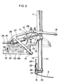
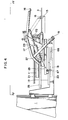
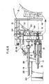
- FIGs. 3 to 5 show, in a larger scale, a device for grasping and picking up the U-tube 3 and a device for clamping the U-tube from the upper and lower sides of the later.
- a reference numeral 11 designates a fluid actuator having a piston rod 10 which in turn is provided at its end with claws 13, 14 for gripping the bent portion of the U-tube.
- the fluid actuator 11 is mounted on a table 27 through joint members 70, 71 which can be flexed at pivot portion 72. Another connection between the fluid actuator 11 and the table 27 is made through a pair of fluid actuator 12. (see Fig.
- the fluid actuator 11 is rotatable around the pivot portion 72 between a first position in which is to substantially perpendicular to the tube inserting direction and a second position in which the same is held in parallel with the tube inserting direction, by the extending and retracting operation of the fluid actuator 12.
- the table 27 is mounted on another table 26 and is adapted to be slightly adjustable in the rotational direction with respect to the tabe 26.
- the table 26 is movable along rails 19 laid on a support 20 and is adapted to be driven by a fluid actuator 18 mounted on the support 20.
- the fluid actuator 18 is connected to the table 26 in such a manner as to drive the table 26 in the tube inserting direction through the intermediary of a spring 68.
- a limit switch 67 is secured to the support 20. This limit switch is activated to stop the inserting operation when the table 26 is retracted rearwardly against the force of the spring 68 due to, for instance, a collision of the U-tube with a partition plate during the insertion.
- the support 20 is movable along rails provided on the truck 1 and extending in the heightwise direction (see Fig. 4), so as to be driven up and down on the truck 1 by the operation of a motor mounted on the truck 1, under the control by the control unit.
- a guide bar 21 is provided for sliding movement in parallel with the fluid actuator 11, and is connected at its end to the end of the piston rod by a connecting member.
- the claw 13 has a recess of curvature for fitting the outer surface of the U-tube 3 and is fixed to the connecting member.
- the claw 14 has a hook-like shape and is pivotally connected to the claw 13 such that the recess of the claw 13 and the hook-shaped portion of the claw 14 are moved towards and away from each other by the operation of a fluid actuator 22.
- the fluid actuator 22 is started as the sensor 23 senses the presence of the U-tube to make the grip and release of the bent portion of the U-tube 3.
- a fluid actuator 24 is connected to the sensor 23 to lift the same and is used whenever the operation of the claw 14 is necessary, regardless of the presence of the U-shaped tube 3.
- a pair of guide bars 25 one of which is shown in Fig. 5, are provided on the table 27 for sliding movement in parallel with the actuator 11.
- a plate 36 is attached to the ends of the guide bars 25 so as to extend transversely of the tube inserting direction.
- the plate 36 is provided with a notch adapted to engage with a groove 35 formed in a part of the claw 13 when the actuator 11 is rotated from the vertical position shown in Fig. 3 to a horizontal position shown in Fig. 4 after the piston rod 10 is retracted.
- the U-tube holding apparatus A further has a device for clamping the U-tube 3, while the U-tube is held by the claws 13, 14 and lifted by the actuator 11, from the upper and lower side of the latter.
- the device includes a pressing plate 16 which operates to press the U-tube 3 from the upper side, a pressing plate 15 for pressing the U-tube from the lower side and a pair of fluid actuators 17 adapted to drive these pressing plates.
- Both of the pressing plates 15 and 16 are pivotally secured to the support 28, and are swung as indicated by two-dot-and- dash lines and full lines in Figs. 3 and 4 by the operation of the actuators 17 which are connected at their ends to the pressing plate 15 and their other ends to the pressing plate 16, respectively.
- the U-tube holding apparatus constructed as explained hereinbefore, is shown in Fig. 1 in a state in which the fluid actuator 11 is in the vertical posture. In this state, the U-tube 3 gripped by the clows is lifted as the piston rod 10 is retracted.
- Fig. 5 which shows a half part of the U-tube holding apparatus
- reference numerals 29, 30 and 31 denote contact pieces which are mounted on the plate 36. These contact pieces 29, 30 and 31 are adapted to contact with the bent portion of the U-tube by the operation of respective fluid actuators 32, 33 and 34 so as to apply the inserting force uniformly along the curvature of the bent portion of the U-tube in the inserting operation.
- a reference numeral 7 designates a frame which defines an opening in the tube inserting direction.
- the aforementioned saddle 38 is disposed in the opening of the frame 7.
- the saddle 38 is provided in its both side portions with threaded holes which engage with screw shafts extending in the heightwise direction from bottom ends of the frame 7, respectively.
- the screw shafts on both sides of the frame 7 are adapted to be driven simultaneously by a motor which is provided on the bottom of the frame 7, thereby to drive the saddle 38 up and down.
- the vertical movement of the saddle 38 is guided by rails 65 and 66 which are provided on both side portions of the frame 7.
- a pair of saddles 39 are mounted on the saddle 38, for movement along the rails 63, 64 which extend transversely of the tube inserting direction.
- a screw shaft 62 is rotatably provided on the saddle 38 to extend along the rails 63, 64.
- the screw shaft 62 is drivingly connected through a belt 61 to a motor 60 which is also mounted on the saddle 38.
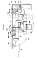
- the screw shaft 62 have two halves which are threaded in opposite directions. These threaded halves mesh with corresponding saddles 39 as shown in Fig. 7. Therefore, when the screw shaft 62 rotates, the saddles 39 are moved towards each other or away from each other depending on the direction of rotation of the motor 60.
- Each of the saddles 39 carries a guide 40 and three sets of guide rollers each having vertical guide rollers and horizontal guide rollers, in alignment with each other in the tube inserting direction.
- the guide 40 has a configuration suitable for guiding the U-tube 3 to the guide rollers and is provided at its lower portion with a groove for receiving a supporting bar 37.
- the supporting bar 37 is a bar which extends, as shown in Figs. 1 and 2, outwardly of the frame 7 along the lower portion of the latter.
- the supportihg bar 37 is connected at its both ends to operating mechanisms provided on both sides of the frame 7. Each of these mechanisms is provided with a pair of actuators. By the operation of the actuators, the supporting bar 37 is moved from the position shown by two- dot-and-dash line in Fig.
- Each set of guide rollers has a pair of lateral guide rollers 41, 42 and a pair of horizontal guide rollers 43, 44.
- the upper one 44 of the horizontal guide rollers is drivingly connected to a fluid actuator 45 mounted on the saddle 39 as shown in Fig. 7 so that it comes into contact with or gets out of contact with the U-tube 3 in accordance with the operation of this actuator 45.
- a pair of saddles 39 are moved under the control of the control unit D in accordance with the distance between parallel straight portions of the U-tube 3.
- the saddle 38 is moved up and down in accordance with the level of the gripping device of the U-tube holding apparatus so as to make the saddle 38 hold the parallel portions of the U-tube while keeping the latter horizontally.
- a device for washing the U-tube and a device for polishing the same are incorporated in the positioning apparatus.
- the washing device includes a washing member 46 disposed between second and third set of guide rollers on each saddle 39.
- the washing member 46 is driven by a rotary actuator 47 mounted on the lower side of the saddle 39 between the rails 63 and 64, so as to be rotated between a position where the end of the washing member 46 contacts the U-tube on the saddle 39 and a position in which the end of the washing member 46 is immersed in a washing liquid disposed at the lower side of the saddle 38.
- Each of washing members 46 is provided with an actuator 59 by which its end is opened and closed selectively.
- the washing member 46 carries at its end a sponge 58 which is adapted to be impregnated with the washing liquid.
- the washing member 46 After impregnation of the sponge 58 with the washing liquid, the washing member 46 is rotated upwardly so that the sponge 58 is held on the path of movement of the U-tube 3 to make contact with the latter. Consequently, only contaminates which would impair the welding are removed from the surface of the U-tube.
- the polishing device includes a pair of saddles 56 movably carried by rails disposed in the vicinity of leading end edge of the saddle 39 as viewed in the tube inserting direction, the rails being extended in parallel with the rails 63, 64 on the saddles 38.
- a saddle 55 is mounted on each saddle 56 for movement in the tube inserting direction, and an actuator 57 mounted on the saddle 56 is drivingly connected to this saddle 55.
- Each saddle 55 is provided at its trailing end as viewed in the tube inserting direction with a dog 50 which has a groove conforming with a projection of a dog 49 provided on the associated saddle 39, as will be seen from Fig. 8.
- each set of the saddle 55 and saddle 56 is moved together with the associated saddle 39.
- Each saddle 56 is provided with a brake 69 which starts to operate to engage with the rail simultaneously with the start of the operation of the actuator 55 in the direction for breaking the engagement between the dogs 49 and 50, i.e. in the tube inserting direct. As a result of the operation of the brake, the saddles 56 remain at the positions where the dogs are disengaged from each other.
- Each saddle 55 further carries a flap wheel 51, a motor for driving this flap wheel and a sensor including a contactor 53 and a limit switch 54.
- the contactor 53 of the sensor is positioned to activate the limit switch 54 when pressed by the end of the U-tube 3 which has been driven into the positioning apparatus.
- the end portion of the contactor 53 is concaved to receive a guide 52 attached to the end of the U-tube 3.
- the guide 52 is a bullet- shaped member made of a plastic attached to each end of the U-tube 3 to facilitate the passing of the tube ends through the holes in the partition plates 8.
- the flap wheel 51 is disposed in parallel with the U-tube so as to rotate in contact with the U-tube 3 and to revolve around the latter, and is driven in accordance with the operation of the limit switch 54.
- the partition plate holding apparatus C can have any construction constituted by known technics, provided that it can removably fix a predetermined number of partition plates at predetermined positions and levels.
- the control unit D can have any known arrangement which has a control circuit including a computer and is adapted to control the operation of the above-described apparatus in a sequence which will be described later. No further description will be needed for the construction of the partition plate holding apparatus C and the control unit D.
- the apparatus A, B and C should be arranged in predetermined relationship in the horizontal plane and in the heightwise direction, in accordance with the kind and other conditions of the U-tubes to be inserted.
- these apparatus may be installed for independent adjustment of their position and height, provided that the relationship described as above can be settled during the automatic inserting operation.
- the partition plates 8 are fixed on the partition plate holding apparatus C with the corresponding holes of these plates 8 in axial alignment with each other.
- the box 4 accommodating a multiplicity of U-tubes in a predetermined manner is placed in the U-tube holding apertures A.
- a multiplicity of holes of each partition plate are formed in parallel rows.
- each row is arranged so that the U-tube having the smallest radius of curvature is inserted first into a pair of holes arranged at the innermost of the raw and then the U-tubes having progressively increasing radii of curvature are successively inserted into pairs of holes arranged outside of the innermost holes in order of size of radius to stride over the inserted U-tube one after another.
- the box 4 houses the U-tubes in a plurality of layers, each layer including U-tubes arranged in accordance with the order or sequence of the insertion, i.e. such that the U-tube of smallest radius of curvature is positioned at the innermost position and the U-tubes having progressively increasing radii of curvature are disposed at the outer side successively.
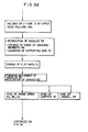
- control unit D is manually operated to effect the initial set up of the automatic tube inserting system as follows.
- the automatic tube insertion system is started after the above initial set up.
- the operation is commenced in accordance with the program which is beforehand set in the NC circuit of the control unit, so that the actuator 11 of the U-tube holding apparatus is operated to lower the claws 13 and 14 attached to the end of the piston rod 10.
- the sensor 23 operates to make a confirming signal upon receipt of which the control unit operates the actuator 22 thereby to make the claws 13 and 14 grip the U-tube 3.
- the claws 13 and 14 are moved upwardly by the actuator 11 to lift the U-tube 3 by a predetermined amount.
- the actuator 17 of the clamping device is actuated to move the pressing plates 15 and 16 towards each other to clamp the U-tube 3.
- the control unit delivers an instruction signal also to the positioning apparatus.
- each motor 47 of the washing device Upon receipt of this signal, each motor 47 of the washing device is started to downwardly rotate the washing member 46 to dip the sponge 58 on the end thereof in the washing liquid of the cell 48.
- the actuator 59 makes a repetitional movement in accordance with the instruction given by the control unit so that the end of the washing member 46 is opened and closed repeatedly, thereby removing the contaminates from the sponge 58 and allowing the latter to be impregnated with the washing liquid.
- each washing member 46 is rotated upwardly with the end thereof opened, and is stationed in the path of incoming of the U-tube to prepare for the washing.
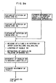
- control unit D effects a 90° rotation of the swing arm 6a of the swing post 5 closest to the truck 1 and raises the same to the level of polishing of the U-tube. Then, the swing arms 6b and 6c are successively operated similarly to the swing arm 6a and, thereafter, the supporting bar 37 of the positioning apparatus is raised through the action of the actuating mechanisms to support the ends of the U-tube 3.
- control unit D operates to start the motor 60 of the positioning apparatus to move the pair of saddles 39, before the rise of the supporting bar 37, until the distance between these saddles 39 comes to coincide with corresponding one of the breadths of the U-tubes which have been beforehand put in the NC circuit in accordance wit_: the order of insertion of the tubes.
- the claws 13 and 14 of the gripping device are moved away from each other by the instruction given from the control unit so that they temporarily release the U-tube 3 to prevent damaging of the U-tube which may be caused during the rotation of the actuator 11.
- the control unit activates the actuator 57 of each polishing device to drive the saddle 55 in the tube inserting direction to release the engagement between the dogs 49 and 50.
- the brakes 69 are actuated at this moment to prevent the saddles 56 from moving the positions reached at the time of disengagement of the dogs 49, 50, i.e. from the positions where the distance between the contactors 53 of the polishing device corresponds to the breadth of the U-tube to be inserted.
- the actuators 12 are operated to turn the actuator 11 sideways.
- the groove 35 formed in the claw 13 is brought into engagement with the notch formed in the plate 36 on the ends of the guide bars 25.
- the control unit operates the actuator 22 to close the claws 13, 14 so that the claws again grip the bent portion of the U-tube 3.
- the control unit then activates the actuators 32, 33 and 34 to move the contact pieces 29, 30 and 31 ahead thereby to bring them into contact with the bent portion of the U-tube 3.
- the motor on the truck 1 is activated so that the truck 1 is moved in the tube inserting direction until the ends of the U-tube come to the positions just in front of respective washing members 46.
- the actuators 45 on respective saddles 39 are activated to rotate the guide rollers 44a and 44b to the positions where they can hold the U-tube.
- the end of each washing member 46 stationed in the path of incoming of the U-tube is closed.
- the control unit restarts the motor of the truck 1 so that the truck 1 is moved ahead over a predetermined distance until the ends of the U-tube are brought to the positions convenient for the polishing.
- the linear portions of the U-tube 3 are rubbed by the sponges 58 which are impregnated with the washing liquid and held by the ends of the washing members 46, so that the outer surfaces of the U-tube is washed and cleaned.
- the remaining actuators 45 are operated under the control by the control unit to make the guide rollers 44c on the saddles 39 hold the U-tube 3.
- the actuators 57 of the polishing device are operated to move the saddles 55 in the direction counter to the tube inserting direction.
- the contactors . 53 of the sensors on respective saddles are brought into contact with the guides 52 on the ends of the U-tube 3 to activate the limit switches 54.
- the ends of the cleaning members 46 are opened and the supporting bar 37 is lowered. Thereafter, the flap wheel 51 in contact with each end of the U-tube is driven to rotate while making a revolution around each end, thereby polishing the end of the U-tube 3.
- the saddles 55 are moved in the tube inserting direction.
- the swing arms 6a, 6b, 6c of the U-tube holding apparatus together with the support 20 of the truck 1 and the saddle 38 of the positioning apparatus, are raised under the control of the control unit D to the level of the aimed holes in the partition plates 8.
- the truck 1 starts to move again in the tube inserting direction to insert the U-tube into the aimed holes in the partition plates 8.
- this swing arm is further rotated 90° by the control of the control unit D to come out of the path of movement of the truck 1.
- Similar operation is carried out with the swing arm 6b and then with the swing arm 6c as the truck 1 further moves in the tube inserting direction.
- the truck 1 advances to a position which is at a predetermined distance (about 1 m in the illustrated embodiment) from the positioning apparatus.
- the U-tube 3 has been inserted over its half length into the holes in the partition plates 8 when the truck 1 reaches this position.
- the control unit gives an instruction of rotating the guide rollers 44a, 44b, 44c on each saddle 39 through the operation of the actuators 45 to release the U-tube 3 and then lowering the saddle 38 to the level of polishing of the U-tube 3.
- the saddles 55 of the polishing device are retracted to engage the dogs 49 and 50 with each other, while releasing the brakes 69 of respective saddles 56.
- each saddle 39 is moved to the position above the cell 48 which contains the washing liquid. After the movement of saddles 39, the truck 1 is moved ahead to the final position required for the full insertion of the U-tube 3.
- the actuators 17 of the clamping device are operated under the control of the control unit to move the pressing plates 15 and 16 away from each other thereby to release the U-tube 3.
- the actuator 11 is operates to extend its piston rod 10 to move the plate 36 ahead, thereby inserting the U-tube into the partition plates 8 to the final position.
- the control unit D then operates the actuator 22 of the gripping device to swing the claw 14 away from the claw 13, thereby to release the U-tube 3 from the gripping device.
- the actuators 32, 33 and 34 are operated to return the contact pieces 29, 30 and 31 to the starting positions.
- the piston rod 10 of the actuator 11 is retracted in this stage thereby retracting the plate 36. Meanwhile, the truck 1 moves backwardly to bring the gripping device to a position convenient for picking up the next U-tube to be inserted.
- the data concerning the distances between the bent portions of adjacent tubes are beforehand inputted to the NC circuit of the control unit, so that the truck 1 can move backwardly to the position convenient for the picking up of the bent portion of the U-tube to be inserted next.
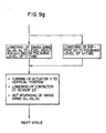
- the actuator 11 is rotated to resume the vertical posture.
- the contactor of the sensor 23 projects from the claw 13 by the gravity.
- the swing arms 6a, 6b and 6c are rotated 180° reversely to return to the initial positions.
- the series of operation described hereinabove is repeated cyclically to successively insert a plurality of U-tubes into the holes in the partition plates.
- the automatic tube inserting system of the invention it is possible to automatically insert the U-tubes into the object such as the partition plates of a heat exchanger without causing any damage on the U-tube.
- the invention therefore, greatly contributes to the saving of labour-in assembling of equipments which have U-shaped heat transfer tubes, as well as to the improvement in the quality of the assembled products.
Landscapes
- Engineering & Computer Science (AREA)
- Mechanical Engineering (AREA)
- Automatic Assembly (AREA)
Applications Claiming Priority (2)
| Application Number | Priority Date | Filing Date | Title |
|---|---|---|---|
| JP87749/83 | 1983-05-20 | ||
| JP58087749A JPS59214523A (ja) | 1983-05-20 | 1983-05-20 | 熱交換器等のu字管の自動插入装置 |
Publications (3)
| Publication Number | Publication Date |
|---|---|
| EP0126457A2 true EP0126457A2 (de) | 1984-11-28 |
| EP0126457A3 EP0126457A3 (en) | 1985-04-10 |
| EP0126457B1 EP0126457B1 (de) | 1987-08-12 |
Family
ID=13923578
Family Applications (1)
| Application Number | Title | Priority Date | Filing Date |
|---|---|---|---|
| EP84105671A Expired EP0126457B1 (de) | 1983-05-20 | 1984-05-18 | Vorrichtung zum automatischen Einfügen der U-Rohre in Wärmetauscher |
Country Status (5)
| Country | Link |
|---|---|
| US (1) | US4543711A (de) |
| EP (1) | EP0126457B1 (de) |
| JP (1) | JPS59214523A (de) |
| CA (1) | CA1216144A (de) |
| DE (1) | DE3465260D1 (de) |
Cited By (2)
| Publication number | Priority date | Publication date | Assignee | Title |
|---|---|---|---|---|
| GB2257061A (en) * | 1991-06-26 | 1993-01-06 | Ford Motor Co | Inserting u-shaped heat exchanger tubes in a heat exchanger core. |
| CN112264536A (zh) * | 2020-10-29 | 2021-01-26 | 武汉凯比思电力设备有限公司 | 一种列管式换热器自动穿管设备 |
Families Citing this family (31)
| Publication number | Priority date | Publication date | Assignee | Title |
|---|---|---|---|---|
| US4625396A (en) * | 1984-12-27 | 1986-12-02 | Westinghouse Electric Corp. | Pattern fuel assembly loading system |
| DE3509177C1 (de) * | 1985-03-14 | 1986-10-02 | Brown Boveri Reaktor GmbH, 6800 Mannheim | Einrichtung zum Einbringen eines zylindrischen Koerpers,insbesondere einer Huelse,in ein Rohr eines Dampferzeugers |
| US4649632A (en) * | 1985-11-18 | 1987-03-17 | General Electric Company | Fuel bundle assembly machine |
| US4720902A (en) * | 1986-12-22 | 1988-01-26 | Carrier Corporation | One step tension expander and method of using |
| US4829648A (en) * | 1987-01-27 | 1989-05-16 | Westinghouse Electric Corp. | Apparatus and method for simultaneously loading a reinforcing sleeve and mandrel into a tube |
| US4760637A (en) * | 1987-05-06 | 1988-08-02 | Westinghouse Electric Corp. | Reduced stress fuel assembly fabrication apparatus and method |
| US5228191A (en) * | 1989-10-16 | 1993-07-20 | Richard Casterline | Apparatus for making a barrel type fluid heat exchanger |
| US5002120A (en) * | 1990-03-08 | 1991-03-26 | Boisture Thomas B | Multi-lance tube cleaning system |
| US5031691A (en) * | 1990-03-08 | 1991-07-16 | Ohmstede Mechanical Services, Inc. | Multi-lance tube cleaning system having sliding plate |
| US5067558A (en) * | 1990-03-08 | 1991-11-26 | Ohmstede Mechanical Services, Inc. | Multi-lance tube cleaning system |
| US5022463A (en) * | 1990-03-08 | 1991-06-11 | Ohmstede Mechanical Services, Inc. | Multi-hose flexible lance tube cleaning system |
| US5129455A (en) * | 1990-03-08 | 1992-07-14 | Ohmstede Mechanical Services, Inc. | Multi-lance tube cleaning system having flexible portions |
| US5322410A (en) * | 1992-01-22 | 1994-06-21 | Stewart & Stevenson Services, Inc. | Tube bundle extractor |
| JP3315151B2 (ja) * | 1992-07-02 | 2002-08-19 | 日高精機株式会社 | 熱交換器組立装置のパイプ挿入装置 |
| US5323529A (en) * | 1992-12-10 | 1994-06-28 | American Mechanical Services, Inc. | Heat exchanger bundle extractor assembly and method |
| US5632080A (en) * | 1994-07-26 | 1997-05-27 | Burr Oak Tool & Gauge Company, Inc. | Tube cutter/bender to lacer transfer station |
| US5687473A (en) * | 1994-10-05 | 1997-11-18 | Kyoshin Kogyo Co., Ltd. | Apparatus and method for mounting a hairpin tube to a heat exchanger |
| JP3300609B2 (ja) * | 1996-08-07 | 2002-07-08 | 株式会社東芝 | 熱交換器の熱交換用チューブ組立て装置および組立て方法 |
| US5979041A (en) * | 1997-04-29 | 1999-11-09 | Ahaus Tool & Engineering, Inc. | Apparatus for assembling heat exchangers |
| US6308409B1 (en) | 1999-05-05 | 2001-10-30 | Solar Turbines Incorporated | Recuperator cell assembly system |
| KR100480484B1 (ko) * | 2002-06-15 | 2005-04-06 | 주식회사 우진 | 프로브용 측온센서 자동 압입장치 |
| US8365407B2 (en) * | 2009-04-14 | 2013-02-05 | Neng Tyi Precision Industries Co., Ltd. | Radiator manufacturing method and aligning-and-moving mechanism thereof |
| CN102161157B (zh) * | 2011-04-27 | 2013-04-03 | 上海九段精密机电科技有限公司 | 一种汽车热交换器芯装配生产线及其工作方法 |
| ITCR20120010A1 (it) * | 2012-04-05 | 2013-10-06 | Maus Italia F Agostino & C Sas | Procedimento di assemblaggio di un fascio tubiero per scambiatori di calore |
| US9612063B2 (en) * | 2014-07-31 | 2017-04-04 | Altex Industries Inc. | Support for a heat exchanger tube bundle |
| CN107520590B (zh) * | 2017-09-28 | 2023-10-20 | 深圳市捷牛智能装备有限公司 | 智能装管设备及其装管工艺 |
| EP3946775B1 (de) * | 2019-04-04 | 2024-07-31 | MBK MASCHINENBAU GmbH | Vorrichtung zur bestueckung einer korbschweissmaschine und korbschweissmaschine |
| CN112059843A (zh) * | 2020-09-18 | 2020-12-11 | 嘉兴金亿新材料股份有限公司 | 木质包装箱加工生产线 |
| CN115106764B (zh) * | 2022-08-11 | 2024-06-04 | 武汉凯比思电力设备有限公司 | 一种换热器智能自动穿管生产线 |
| CN116967763B (zh) * | 2023-09-25 | 2024-02-20 | 广东赛普智能制造股份有限公司 | 一种管体加工系统及其应用 |
| CN117340577B (zh) * | 2023-11-03 | 2025-03-14 | 山东一明节能环保设备科技有限公司 | 一种空气预热器生产组装装置 |
Family Cites Families (17)
| Publication number | Priority date | Publication date | Assignee | Title |
|---|---|---|---|---|
| US1802929A (en) * | 1929-11-18 | 1931-04-28 | Mcquay Radiator Corp | Heat-exchange core-assembling machine |
| GB1111140A (en) * | 1966-02-07 | 1968-04-24 | Hudson Engineering Corp | Manufacture of metal plate fin tube modules |
| US3574917A (en) * | 1968-07-31 | 1971-04-13 | Toyo Radiator Co Ltd The | Machine for assembling the core of heat exchanger |
| US3785506A (en) * | 1971-09-10 | 1974-01-15 | Roger A Crocker | Drill pipe handling apparatus |
| US3789479A (en) * | 1972-06-30 | 1974-02-05 | Mordo Co | Machine for assembling tubes in a heat exchanger |
| US3810553A (en) * | 1972-08-31 | 1974-05-14 | R Crocker | Pipe handling device |
| US3824668A (en) * | 1973-01-26 | 1974-07-23 | Emerson Electric Co | Continuous stroke tube insertion and expanding device |
| DE2620406B2 (de) * | 1976-05-08 | 1980-04-03 | Gerhard 4600 Dortmund Hindrichs | Montagevorrichtung zum Einschieben der Rohre in die Rohrboden von großen Wärmetauschanlagen |
| DE2643632A1 (de) * | 1976-09-28 | 1978-03-30 | Kraftwerk Union Ag | Vorrichtung zum zufuehren von rohren fuer waermetauscher |
| JPS53119274A (en) * | 1977-03-29 | 1978-10-18 | Ube Ind Ltd | Batch distillation method |
| US4125928A (en) * | 1977-08-17 | 1978-11-21 | Ohmstede Machine Works, Inc. | Method and apparatus for pulling tubes from heat exchanger baffles |
| JPS6047121B2 (ja) * | 1977-09-30 | 1985-10-19 | 株式会社日立製作所 | 車輪装着装置 |
| JPS5626644A (en) * | 1979-08-11 | 1981-03-14 | Mitsui Eng & Shipbuild Co Ltd | Pipe inserting device of multitubular heat exchanger |
| IT1132450B (it) * | 1979-08-24 | 1986-07-02 | Kobe Steel Ltd | Macchina per l'inserimento di tubi |
| DE3019017A1 (de) * | 1980-05-19 | 1981-12-03 | KK Automation Klaus Th. Krämer GmbH & Co KG, 7107 Neckarsulm | Handhabungssystem fuer werkstuecke |
| JPS5733937A (en) * | 1980-07-29 | 1982-02-24 | Meiji Gomme Kasei:Kk | Caulking device for hose metal fittings |
| US4380868A (en) * | 1981-03-30 | 1983-04-26 | United Aircraft Products, Inc. | Tube loading apparatus |
-
1983
- 1983-05-20 JP JP58087749A patent/JPS59214523A/ja active Pending
-
1984
- 1984-05-15 US US06/610,409 patent/US4543711A/en not_active Expired - Fee Related
- 1984-05-16 CA CA000454457A patent/CA1216144A/en not_active Expired
- 1984-05-18 EP EP84105671A patent/EP0126457B1/de not_active Expired
- 1984-05-18 DE DE8484105671T patent/DE3465260D1/de not_active Expired
Cited By (4)
| Publication number | Priority date | Publication date | Assignee | Title |
|---|---|---|---|---|
| GB2257061A (en) * | 1991-06-26 | 1993-01-06 | Ford Motor Co | Inserting u-shaped heat exchanger tubes in a heat exchanger core. |
| WO1993000198A1 (en) * | 1991-06-26 | 1993-01-07 | Ford Motor Company Limited | Inserting u-shaped heat exchanger tubes in a heat exchanger core |
| US5369876A (en) * | 1991-06-26 | 1994-12-06 | Ford Motor Company | Apparatus for inserting U-shaped tubes in a heat exchanger core |
| CN112264536A (zh) * | 2020-10-29 | 2021-01-26 | 武汉凯比思电力设备有限公司 | 一种列管式换热器自动穿管设备 |
Also Published As
| Publication number | Publication date |
|---|---|
| DE3465260D1 (en) | 1987-09-17 |
| JPS59214523A (ja) | 1984-12-04 |
| CA1216144A (en) | 1987-01-06 |
| US4543711A (en) | 1985-10-01 |
| EP0126457B1 (de) | 1987-08-12 |
| EP0126457A3 (en) | 1985-04-10 |
Similar Documents
| Publication | Publication Date | Title |
|---|---|---|
| US4543711A (en) | System for automatically inserting U-tubes of heat exchanger or the like | |
| CN1131761C (zh) | 热交换器的热交换器用管组装装置及组装方法 | |
| CN112379243B (zh) | 一种电路板常温测试自动上下料与插拔系统及方法 | |
| CN111646204B (zh) | 多工位曲轴自动化三维测量系统 | |
| US4058017A (en) | Automatic probe feeding, setting and withdrawing apparatus | |
| CN107052815A (zh) | 一种全自动去除马达转子换向器毛刺和铜粉屑的去毛刺机及其操作方法 | |
| GB2217244A (en) | Work manipulating apparatus for sheet bending machine | |
| EP0297541B1 (de) | Automatische Vorrichtung zum Abtasten eines Rohrumfanges | |
| CA1332619C (en) | Manipulator for a plate bending machine and a robotic device equipped with said manipulator | |
| CN104959892B (zh) | 一种水晶坯件磨抛系统 | |
| CN211516352U (zh) | 一种带自动弯脚功能的全自动浸锡机 | |
| CN212120885U (zh) | 一种板材清洁装置 | |
| EP0434868B1 (de) | Einrichtung zur Inspektion und Reparatur der Rohre eines Atomkraftwerks | |
| CN218447050U (zh) | 一种工业机器人自动上下料实训装置 | |
| CN110340715A (zh) | 一种型材生产线用的上料装置 | |
| CN112157663B (zh) | 套被机器人 | |
| US4683649A (en) | Device for assembling return bend to coil | |
| CN212762385U (zh) | 一种二拖二式桁架机械手装置 | |
| US4747208A (en) | Device for assembling return bend to coil | |
| CN223229621U (zh) | 一种水泥胶砂试件存储传输装置 | |
| CN223632355U (zh) | 一种新型积放链旋转吊具自动找正及扶正机构 | |
| CN223229330U (zh) | 一种用于放置折断后的水泥胶砂试件的中转台 | |
| CN219561850U (zh) | 一种激光打标机的抓取装置 | |
| JPS63172B2 (de) | ||
| CN121608183A (zh) | 一种用于取水口粗格栅检修作业的机械手末端装置 |
Legal Events
| Date | Code | Title | Description |
|---|---|---|---|
| PUAI | Public reference made under article 153(3) epc to a published international application that has entered the european phase |
Free format text: ORIGINAL CODE: 0009012 |
|
| AK | Designated contracting states |
Designated state(s): DE FR GB |
|
| PUAL | Search report despatched |
Free format text: ORIGINAL CODE: 0009013 |
|
| AK | Designated contracting states |
Designated state(s): DE FR GB |
|
| 17P | Request for examination filed |
Effective date: 19850412 |
|
| 17Q | First examination report despatched |
Effective date: 19860221 |
|
| GRAA | (expected) grant |
Free format text: ORIGINAL CODE: 0009210 |
|
| AK | Designated contracting states |
Kind code of ref document: B1 Designated state(s): DE FR GB |
|
| REF | Corresponds to: |
Ref document number: 3465260 Country of ref document: DE Date of ref document: 19870917 |
|
| ET | Fr: translation filed | ||
| PLBE | No opposition filed within time limit |
Free format text: ORIGINAL CODE: 0009261 |
|
| STAA | Information on the status of an ep patent application or granted ep patent |
Free format text: STATUS: NO OPPOSITION FILED WITHIN TIME LIMIT |
|
| 26N | No opposition filed | ||
| PGFP | Annual fee paid to national office [announced via postgrant information from national office to epo] |
Ref country code: FR Payment date: 19890410 Year of fee payment: 6 |
|
| PGFP | Annual fee paid to national office [announced via postgrant information from national office to epo] |
Ref country code: GB Payment date: 19890531 Year of fee payment: 6 |
|
| PGFP | Annual fee paid to national office [announced via postgrant information from national office to epo] |
Ref country code: DE Payment date: 19890621 Year of fee payment: 6 |
|
| PG25 | Lapsed in a contracting state [announced via postgrant information from national office to epo] |
Ref country code: GB Effective date: 19900518 |
|
| GBPC | Gb: european patent ceased through non-payment of renewal fee | ||
| PG25 | Lapsed in a contracting state [announced via postgrant information from national office to epo] |
Ref country code: FR Effective date: 19910131 |
|
| PG25 | Lapsed in a contracting state [announced via postgrant information from national office to epo] |
Ref country code: DE Effective date: 19910201 |
|
| REG | Reference to a national code |
Ref country code: FR Ref legal event code: ST |