EP0126655A2 - Unter Vakuum arbeitende Ausdruckanlage für Trommeldrehfilter - Google Patents
Unter Vakuum arbeitende Ausdruckanlage für Trommeldrehfilter Download PDFInfo
- Publication number
- EP0126655A2 EP0126655A2 EP84303519A EP84303519A EP0126655A2 EP 0126655 A2 EP0126655 A2 EP 0126655A2 EP 84303519 A EP84303519 A EP 84303519A EP 84303519 A EP84303519 A EP 84303519A EP 0126655 A2 EP0126655 A2 EP 0126655A2
- Authority
- EP
- European Patent Office
- Prior art keywords
- filter
- drum
- cake
- vacuum
- rolls
- Prior art date
- Legal status (The legal status is an assumption and is not a legal conclusion. Google has not performed a legal analysis and makes no representation as to the accuracy of the status listed.)
- Withdrawn
Links
Images


Classifications
-
- B—PERFORMING OPERATIONS; TRANSPORTING
- B30—PRESSES
- B30B—PRESSES IN GENERAL
- B30B9/00—Presses specially adapted for particular purposes
- B30B9/02—Presses specially adapted for particular purposes for squeezing-out liquid from liquid-containing material, e.g. juice from fruits, oil from oil-containing material
- B30B9/24—Presses specially adapted for particular purposes for squeezing-out liquid from liquid-containing material, e.g. juice from fruits, oil from oil-containing material using an endless pressing band
- B30B9/241—Presses specially adapted for particular purposes for squeezing-out liquid from liquid-containing material, e.g. juice from fruits, oil from oil-containing material using an endless pressing band co-operating with a drum or roller
-
- B—PERFORMING OPERATIONS; TRANSPORTING
- B01—PHYSICAL OR CHEMICAL PROCESSES OR APPARATUS IN GENERAL
- B01D—SEPARATION
- B01D33/00—Filters with filtering elements which move during the filtering operation
- B01D33/06—Filters with filtering elements which move during the filtering operation with rotary cylindrical filtering surfaces, e.g. hollow drums
- B01D33/073—Filters with filtering elements which move during the filtering operation with rotary cylindrical filtering surfaces, e.g. hollow drums arranged for inward flow filtration
-
- B—PERFORMING OPERATIONS; TRANSPORTING
- B01—PHYSICAL OR CHEMICAL PROCESSES OR APPARATUS IN GENERAL
- B01D—SEPARATION
- B01D2201/00—Details relating to filtering apparatus
- B01D2201/28—Position of the filtering element
- B01D2201/282—Filtering elements with a horizontal rotation or symmetry axis
-
- B—PERFORMING OPERATIONS; TRANSPORTING
- B01—PHYSICAL OR CHEMICAL PROCESSES OR APPARATUS IN GENERAL
- B01D—SEPARATION
- B01D33/00—Filters with filtering elements which move during the filtering operation
- B01D33/44—Regenerating the filter material in the filter
- B01D33/46—Regenerating the filter material in the filter by scrapers, brushes nozzles or the like acting on the cake-side of the filtering element
-
- B—PERFORMING OPERATIONS; TRANSPORTING
- B01—PHYSICAL OR CHEMICAL PROCESSES OR APPARATUS IN GENERAL
- B01D—SEPARATION
- B01D33/00—Filters with filtering elements which move during the filtering operation
- B01D33/58—Handling the filter cake in the filter for purposes other than for regenerating the filter cake remaining on the filtering element
- B01D33/60—Handling the filter cake in the filter for purposes other than for regenerating the filter cake remaining on the filtering element for washing
-
- B—PERFORMING OPERATIONS; TRANSPORTING
- B01—PHYSICAL OR CHEMICAL PROCESSES OR APPARATUS IN GENERAL
- B01D—SEPARATION
- B01D33/00—Filters with filtering elements which move during the filtering operation
- B01D33/58—Handling the filter cake in the filter for purposes other than for regenerating the filter cake remaining on the filtering element
- B01D33/62—Handling the filter cake in the filter for purposes other than for regenerating the filter cake remaining on the filtering element for drying
- B01D33/64—Handling the filter cake in the filter for purposes other than for regenerating the filter cake remaining on the filtering element for drying by compression
- B01D33/642—Handling the filter cake in the filter for purposes other than for regenerating the filter cake remaining on the filtering element for drying by compression by pressure belts
Definitions
- the present invention is directed to new and useful improvements in rotary vacuum drum filters and more particularly to vacuum expression means and method for dewatering and compressing filter cake.
- Rotary vacuum drum filters are well known and have many industrial and municipal uses. For example, in the municipal area such filters have been used to process sewage , sludge and in the pulp and paper industry such filters are used for brownstock washing and to filter and wash pulp slurries.
- the filters generally comprise a cylindrical drum mounted for rotation in a tank containing a slurry solution.
- a filter media such as a filter cloth is provided about the drum and as the drum is rotated through a filtration cycle a vacuum is maintained inside the drum during a portion of the cycle whereby a filter cake is formed on the surface of the filter media.
- As the drum ascends from the tank the filtrate is drawn into suitable filtrate compartments in the drum by the applied vacuum.
- Another object is to provide an air tight expressor device which includes novel means for mounting the device on the outer surface of a rotary drum filter requiring a minimum area of operation.
- Another object is to provide novel press belt expressor means whereby the entire area of the filter cake passing under the belt is contacted by the expression means and is subjected to equal pressure so as to dry to approximately the same uniform moisture content.
- the present invention contemplates a novel vacuum expressor device for a rotary drum filter comprising an endless impervious membrane belt mounted about spaced elongated rolls which extend horizontally across the top of the filter drum.
- Means are provided for detachably mounting the rolls and belt to the filter housing and include brackets at each side of the housing interconnected by an elongated bar member.
- Sprockets are mounted at opposite ends of the belt rolls and are connected to an adjacent bracket.
- Each pair of sprockets are interconnected by chain members to which the side edges of the expressor belt are attached.
- a rotary vacuum drum filter which comprises a pulp washing unit incorporating an embodiment of the present invention is generally indicated by the reference numeral 10 in FIGS. 1 and 2.
- Filter 10 includes a cylindrical drum 11 mounted for rotation in a tank 12 containing a pulp slurry.
- Drum 10 is provided with a plurality of filtrate compartments (not shown) about the outer wall surface thereof.
- a filter media such as a filter cloth 14 is provided about drum 10.
- a liquid pulp slurry is fed to tank 12 and drum 11 is rotated in the direction designated by the arrow A in FIG. 1.
- a vacuum is applied to the filtrate compartments within drum 11 to effect a suction through filter cloth 14 as drum 11 ascends from tank 12 whereby a filter cake 15 adheres to the surface of filter cloth 14 .as the filtrate is drawn into the filtrate compartment for removal from the filter through suitable valves.
- a spray assembly 16 is provided for applying liquid wash to the filter cake 15 in a well known manner.
- a valve assembly (not shown) is operated in a usual manner to interrupt the vacuum to permit removal of the filter cake 15 from the filter cloth 14 by a doctoring device 17 partially shown in FIG. 1.
- an expressor device generally indicated by the reference numeral 20 in FIGS. 1 and 2 is mounted as a detachable unit on filter 10 intermediate spray assembly 16 and doctor device 17 in the applied vacuum cycle of drum 11.
- Expressor device 20 includes two spaced and parallel elongated roll members 21 and 22 which extend horizontally across the top of drum 11. The opposite ends of each roll 21 or 22 are provided with stub shafts 23-24 which are suitably mounted for rotation in spaced brackets 25 and 26 at.opposite end walls of tank 12 as shown with respect to one end wall 27 in FIG. 1. Brackets 25 and 26 are interconnected by an elongated bar member 28 which extends across top of filter 10 intermediate rolls 21 and 22. It is to be understood that the means for mounting rolls 21 and 22 and brackets 25 and 26 are identical at each end wall 27 of filter 10 and the description hereinafter set forth is directed to filter end wall 27 as viewed from the right in FIG. 1 with like reference numerals used to identify corresponding identical parts at each end of expressor device 20.
- sprocket wheels 30-31 are mounted on stub shafts 23-24 intermediate rolls 21-22 and bracket 26.
- An endless chain 33 is wound about in mesh with sprockets 30 and 31 to interconnect rolls 21 and 22 for common movement.
- An air tight press belt 35 comprising an endless impermeable membrane sheet member made from a suitable material such as a polyvinyl elastomeric material is wound about rolls 21 and 22 and has opposite parallel end edges 36 interconnected to chain 33 by connecting pins 37 (FIG. 3).
- Expressor device 20 is mounted on filter 10 for movement towards and away from drum 11 by means of a pneumatic hydraulic lifting assembly which comprises a pneumatic cylindrical actuator 39 having one end 40 pivotally attached to a flange 41 provided on an arcuate shaped end panel 42 of filter 20.
- the projecting piston end of piston 43 is pivotally connected to a boss 44 at the bottom of bracket 26 (FIG. 2).
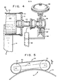
- a second pneumatic actuator comprising a diaphragm type actuator 46 (FIGS. 2 and 4) is mounted on a guide bracket 47 attached to a flange support 48 secured to end panel 42 adjacent the end of roll 22.
- bracket 47 on which actuator 46 is mounted includes spaced legs 50 and 51.
- Actuator 46 is mounted on an interconnecting member 52 with piston 54 thereof extending downward therefrom and interconnected to the end of stub shaft 24.
- the end of shaft 24 is mounted in a housing.55 which is movable on legs 50 and 51 of bracket 47.
- An adjustable stop member comprised of an adjustable nut 56 is mounted in the bite portion 57 of bracket 47 for limiting the downward movement of piston 54 and which in turn limits the downward movement of roll 22.
- Similar stop means are provided for roll 21 and include a threaded fastening and nut member 59 secured to panel 42 to engage and limit the downward movement of bracket 26. In this manner the distance of belt 35 from the surface of drum 11 is readily predetermined through adjustment of stops 56-59.
- Cylindrical actuators 39 and diaphragm actuators 46 are connected to a suitable pneumatic source (not shown) whereby pistons 43 and 54 may be reciprocated to move expressor brackets 25-26 in the directions of arrow B (FIG. 5) to move roll 22 upward and away from filter drum 11.
- piston 54 moves housing 55 up or down on guide legs 50-51 to move roll 22 toward or away from drum 11. Stop means 56 and 57 are so adjusted that expressor belt 35 is adapted to engage the surface of filter cake 15 but will not engage filter cloth 14.
- the pneumatic source may be connected to any suitable control means for selecting timing and sequence of operation of pistons 43 and 54 to operate either in unison or individually in accordance with the needs of the user to provide suitable clearance between expressor 20 and drum 11 for changing or clearing belt 35 or filter cloth 14.
- expressor belt 35 is adapted to cover the entire surface of the filter cake which it engages to provide an air tight compression of the cake in a manner to diminish air passage through the cake and provide more uniform thickness of the cake. As a result cake consistency is improved and the dewatering of the cake greatly enhanced.
- the novel means for mounting expressor device 20 on the filter 10 permits for retrofitting of existing filters with the device.
- the novel hydraulic actuator mounting permits for ready and efficient access to the expressor belt 35 or filter media 14 for cleaning or replacement of parts.
Landscapes
- Engineering & Computer Science (AREA)
- Mechanical Engineering (AREA)
- Chemical & Material Sciences (AREA)
- Chemical Kinetics & Catalysis (AREA)
- Filtration Of Liquid (AREA)
- Centrifugal Separators (AREA)
- Treatment Of Steel In Its Molten State (AREA)
Applications Claiming Priority (2)
| Application Number | Priority Date | Filing Date | Title |
|---|---|---|---|
| US49758883A | 1983-05-24 | 1983-05-24 | |
| US497588 | 1983-05-24 |
Publications (2)
| Publication Number | Publication Date |
|---|---|
| EP0126655A2 true EP0126655A2 (de) | 1984-11-28 |
| EP0126655A3 EP0126655A3 (de) | 1986-06-18 |
Family
ID=23977475
Family Applications (1)
| Application Number | Title | Priority Date | Filing Date |
|---|---|---|---|
| EP84303519A Withdrawn EP0126655A3 (de) | 1983-05-24 | 1984-05-24 | Unter Vakuum arbeitende Ausdruckanlage für Trommeldrehfilter |
Country Status (12)
| Country | Link |
|---|---|
| EP (1) | EP0126655A3 (de) |
| JP (1) | JPS6034708A (de) |
| AU (1) | AU570247B2 (de) |
| BR (1) | BR8402445A (de) |
| CA (1) | CA1233755A (de) |
| FI (1) | FI841859L (de) |
| GB (1) | GB2140318B (de) |
| IN (1) | IN160903B (de) |
| NO (1) | NO842046L (de) |
| NZ (1) | NZ208061A (de) |
| PT (1) | PT78626B (de) |
| ZA (1) | ZA843452B (de) |
Cited By (12)
| Publication number | Priority date | Publication date | Assignee | Title |
|---|---|---|---|---|
| US6267889B1 (en) | 2000-01-26 | 2001-07-31 | Mdf, Llc | Rotary drum filter |
| US20130032543A1 (en) * | 2011-04-05 | 2013-02-07 | Butters Brian E | Decontamination System with Insoluble Additives |
| KR101351271B1 (ko) * | 2012-02-10 | 2014-01-15 | 중앙기계공업 주식회사 | 바큠시크너 |
| CN103691182A (zh) * | 2013-12-07 | 2014-04-02 | 四川锦宇化机有限公司 | 真空转鼓滤碱机 |
| US20140091043A1 (en) * | 2012-09-30 | 2014-04-03 | Daritech, Inc. | Systems and Methods for Separating Solids from Liquids |
| US9597618B2 (en) | 2009-11-05 | 2017-03-21 | Daritech, Inc. | Systems and methods for extracting sand from raw slurry material |
| US9610521B2 (en) | 2009-11-05 | 2017-04-04 | Daritech, Inc. | Systems and methods for extracting particulate from raw slurry material |
| US10286340B2 (en) | 2014-05-27 | 2019-05-14 | Daritech, Inc. | Feed systems and methods for rotary screen separators |
| WO2020035141A1 (en) * | 2018-08-16 | 2020-02-20 | Weld-Tech Engineering Services Limited | Cylindrical filter with support rollers having improved filter replacement arrangement |
| US10603611B2 (en) | 2014-05-30 | 2020-03-31 | Daritech, Inc. | Cleaning systems and methods for rotary screen separators |
| US10603675B2 (en) | 2014-11-02 | 2020-03-31 | Dari-Tech, Inc. | Systems and methods for extracting particulate from raw slurry material |
| CN114653127A (zh) * | 2022-02-28 | 2022-06-24 | 中信重工机械股份有限公司 | 一种用于真空盘式过滤机的自调节刮刀装置 |
Families Citing this family (4)
| Publication number | Priority date | Publication date | Assignee | Title |
|---|---|---|---|---|
| US4737277A (en) * | 1986-11-03 | 1988-04-12 | Dorr-Oliver Incorporated | Vacuum expression belt tracking and control apparatus for rotary drum vacuum filter |
| JPH0592768U (ja) * | 1992-05-20 | 1993-12-17 | 三菱自動車エンジニアリング株式会社 | 車間距離警報装置 |
| JPH0592769U (ja) * | 1992-05-20 | 1993-12-17 | 三菱自動車エンジニアリング株式会社 | 車間距離警報装置 |
| CN107875720B (zh) * | 2017-12-08 | 2019-10-18 | 宁波清智环保科技有限公司 | 生活污水处理装置 |
Family Cites Families (7)
| Publication number | Priority date | Publication date | Assignee | Title |
|---|---|---|---|---|
| US1377765A (en) * | 1921-03-03 | 1921-05-10 | Myrens Verksted As | Revolving suction-strainer |
| GB221311A (en) * | 1923-07-06 | 1924-09-11 | Julius Huebner | Improvements in or relating to the extraction of liquids from paper pulp, sewage sludges and the like by means of suction |
| US2796991A (en) * | 1952-03-21 | 1957-06-25 | Nyquist Borje Sune | Apparatus for the dewatering of suspensions |
| NL7110689A (de) * | 1971-05-17 | 1972-11-21 | ||
| FR2315304A1 (fr) * | 1975-06-26 | 1977-01-21 | Besson Paul | Appareillage pour le filtrage des boues, notamment des boues provenant des eaux residuaires, urbaines ou industrielles |
| FR2416043A1 (fr) * | 1978-02-06 | 1979-08-31 | Degremont Sa | Filtre a bande vibrante |
| GB2077131B (en) * | 1980-05-30 | 1984-03-14 | Gec Diesels Ltd | Filtration |
-
1984
- 1984-05-01 IN IN377/DEL/84A patent/IN160903B/en unknown
- 1984-05-04 NZ NZ208061A patent/NZ208061A/en unknown
- 1984-05-08 ZA ZA843452A patent/ZA843452B/xx unknown
- 1984-05-09 FI FI841859A patent/FI841859L/fi not_active Application Discontinuation
- 1984-05-14 JP JP59097411A patent/JPS6034708A/ja active Pending
- 1984-05-22 PT PT78626A patent/PT78626B/pt unknown
- 1984-05-22 CA CA000454795A patent/CA1233755A/en not_active Expired
- 1984-05-23 NO NO842046A patent/NO842046L/no unknown
- 1984-05-23 AU AU28529/84A patent/AU570247B2/en not_active Expired - Fee Related
- 1984-05-24 EP EP84303519A patent/EP0126655A3/de not_active Withdrawn
- 1984-05-24 GB GB08413387A patent/GB2140318B/en not_active Expired
- 1984-11-24 BR BR8402445A patent/BR8402445A/pt unknown
Cited By (14)
| Publication number | Priority date | Publication date | Assignee | Title |
|---|---|---|---|---|
| US6267889B1 (en) | 2000-01-26 | 2001-07-31 | Mdf, Llc | Rotary drum filter |
| US9610521B2 (en) | 2009-11-05 | 2017-04-04 | Daritech, Inc. | Systems and methods for extracting particulate from raw slurry material |
| US9597618B2 (en) | 2009-11-05 | 2017-03-21 | Daritech, Inc. | Systems and methods for extracting sand from raw slurry material |
| US20130032543A1 (en) * | 2011-04-05 | 2013-02-07 | Butters Brian E | Decontamination System with Insoluble Additives |
| US9133047B2 (en) * | 2011-04-05 | 2015-09-15 | Brian E. Butters | Decontamination system with insoluble additives |
| KR101351271B1 (ko) * | 2012-02-10 | 2014-01-15 | 중앙기계공업 주식회사 | 바큠시크너 |
| US20140091043A1 (en) * | 2012-09-30 | 2014-04-03 | Daritech, Inc. | Systems and Methods for Separating Solids from Liquids |
| CN103691182A (zh) * | 2013-12-07 | 2014-04-02 | 四川锦宇化机有限公司 | 真空转鼓滤碱机 |
| US10286340B2 (en) | 2014-05-27 | 2019-05-14 | Daritech, Inc. | Feed systems and methods for rotary screen separators |
| US10603611B2 (en) | 2014-05-30 | 2020-03-31 | Daritech, Inc. | Cleaning systems and methods for rotary screen separators |
| US10603675B2 (en) | 2014-11-02 | 2020-03-31 | Dari-Tech, Inc. | Systems and methods for extracting particulate from raw slurry material |
| WO2020035141A1 (en) * | 2018-08-16 | 2020-02-20 | Weld-Tech Engineering Services Limited | Cylindrical filter with support rollers having improved filter replacement arrangement |
| CN114653127A (zh) * | 2022-02-28 | 2022-06-24 | 中信重工机械股份有限公司 | 一种用于真空盘式过滤机的自调节刮刀装置 |
| CN114653127B (zh) * | 2022-02-28 | 2023-02-28 | 中信重工机械股份有限公司 | 一种用于真空盘式过滤机的自调节刮刀装置 |
Also Published As
| Publication number | Publication date |
|---|---|
| AU2852984A (en) | 1984-11-29 |
| GB8413387D0 (en) | 1984-06-27 |
| NZ208061A (en) | 1986-07-11 |
| FI841859A7 (fi) | 1984-11-25 |
| BR8402445A (pt) | 1985-04-02 |
| FI841859A0 (fi) | 1984-05-09 |
| ZA843452B (en) | 1984-12-24 |
| AU570247B2 (en) | 1988-03-10 |
| IN160903B (de) | 1987-08-15 |
| PT78626A (en) | 1984-06-01 |
| JPS6034708A (ja) | 1985-02-22 |
| CA1233755A (en) | 1988-03-08 |
| GB2140318A (en) | 1984-11-28 |
| EP0126655A3 (de) | 1986-06-18 |
| PT78626B (en) | 1986-05-30 |
| FI841859L (fi) | 1984-11-25 |
| NO842046L (no) | 1984-11-25 |
| GB2140318B (en) | 1986-06-25 |
Similar Documents
| Publication | Publication Date | Title |
|---|---|---|
| EP0126655A2 (de) | Unter Vakuum arbeitende Ausdruckanlage für Trommeldrehfilter | |
| US3951809A (en) | Filter press | |
| AU7150281A (en) | Dewatering system | |
| US3696930A (en) | Horizontal compression type automatic filter press | |
| US3992298A (en) | Dewatering machine | |
| JPH0857248A (ja) | 湿式排煙脱硫方法及びその装置 | |
| CA1230258A (en) | Filter press for thickening cellulose pulp or sludge | |
| EP0500212A1 (de) | Trommelfilter | |
| NO782567L (no) | Filterinnretning. | |
| US4737277A (en) | Vacuum expression belt tracking and control apparatus for rotary drum vacuum filter | |
| CN112535893A (zh) | 转鼓真空压榨脱水机 | |
| AU723824B2 (en) | Filtration system for removing solid particles | |
| RU2248957C2 (ru) | Машина для обезвоживания сапропеля | |
| JPH07213818A (ja) | 固液分離装置 | |
| US3087538A (en) | Apparatus for extracting liquid from a fiber formation | |
| US2568420A (en) | Filter apparatus | |
| JP4590096B2 (ja) | 濾布ベルト式脱水装置 | |
| JP3786381B2 (ja) | 真空濾過機およびこれを用いた濾過方法 | |
| SU1526756A1 (ru) | Ленточный фильтр-пресс | |
| JPH047241B2 (de) | ||
| JPS6221563B2 (de) | ||
| JPS5912154Y2 (ja) | 圧搾型「ろ」過機 | |
| DE2635738C2 (de) | Saugtrommel-Bandfilter | |
| GB2389061A (en) | Sewage filtration press | |
| JPH0243354Y2 (de) |
Legal Events
| Date | Code | Title | Description |
|---|---|---|---|
| PUAI | Public reference made under article 153(3) epc to a published international application that has entered the european phase |
Free format text: ORIGINAL CODE: 0009012 |
|
| AK | Designated contracting states |
Designated state(s): BE DE FR GB NL SE |
|
| PUAL | Search report despatched |
Free format text: ORIGINAL CODE: 0009013 |
|
| AK | Designated contracting states |
Kind code of ref document: A3 Designated state(s): BE DE FR GB NL SE |
|
| 17P | Request for examination filed |
Effective date: 19861030 |
|
| 17Q | First examination report despatched |
Effective date: 19880831 |
|
| STAA | Information on the status of an ep patent application or granted ep patent |
Free format text: STATUS: THE APPLICATION IS DEEMED TO BE WITHDRAWN |
|
| 18D | Application deemed to be withdrawn |
Effective date: 19890111 |
|
| RIN1 | Information on inventor provided before grant (corrected) |
Inventor name: SPILKIN, GORDON Inventor name: WILLUS, CHARLES ARTHUR Inventor name: KOSONEN, VAINO JUHANI |