EP0126739B1 - A dosing apparatus for dispensing predetermined quantities preferably of beverages from a bottle - Google Patents
A dosing apparatus for dispensing predetermined quantities preferably of beverages from a bottle Download PDFInfo
- Publication number
- EP0126739B1 EP0126739B1 EP83903536A EP83903536A EP0126739B1 EP 0126739 B1 EP0126739 B1 EP 0126739B1 EP 83903536 A EP83903536 A EP 83903536A EP 83903536 A EP83903536 A EP 83903536A EP 0126739 B1 EP0126739 B1 EP 0126739B1
- Authority
- EP
- European Patent Office
- Prior art keywords
- valve
- valve body
- valve device
- dosing apparatus
- bottle
- Prior art date
- Legal status (The legal status is an assumption and is not a legal conclusion. Google has not performed a legal analysis and makes no representation as to the accuracy of the status listed.)
- Expired
Links
- 235000013361 beverage Nutrition 0.000 title abstract description 18
- 230000004913 activation Effects 0.000 claims abstract description 17
- 238000006073 displacement reaction Methods 0.000 claims description 55
- 239000007788 liquid Substances 0.000 claims description 21
- 239000007787 solid Substances 0.000 claims description 6
- 238000007789 sealing Methods 0.000 description 7
- 239000000463 material Substances 0.000 description 3
- 238000004519 manufacturing process Methods 0.000 description 2
- 238000003466 welding Methods 0.000 description 2
- 235000009508 confectionery Nutrition 0.000 description 1
- 238000000151 deposition Methods 0.000 description 1
- 238000000034 method Methods 0.000 description 1
- 230000036316 preload Effects 0.000 description 1
- 238000003825 pressing Methods 0.000 description 1
- 239000007921 spray Substances 0.000 description 1
Images

Classifications
-
- B—PERFORMING OPERATIONS; TRANSPORTING
- B67—OPENING, CLOSING OR CLEANING BOTTLES, JARS OR SIMILAR CONTAINERS; LIQUID HANDLING
- B67D—DISPENSING, DELIVERING OR TRANSFERRING LIQUIDS, NOT OTHERWISE PROVIDED FOR
- B67D1/00—Apparatus or devices for dispensing beverages on draught
- B67D1/08—Details
- B67D1/12—Flow or pressure control devices or systems, e.g. valves, gas pressure control, level control in storage containers
-
- B—PERFORMING OPERATIONS; TRANSPORTING
- B67—OPENING, CLOSING OR CLEANING BOTTLES, JARS OR SIMILAR CONTAINERS; LIQUID HANDLING
- B67D—DISPENSING, DELIVERING OR TRANSFERRING LIQUIDS, NOT OTHERWISE PROVIDED FOR
- B67D3/00—Apparatus or devices for controlling flow of liquids under gravity from storage containers for dispensing purposes
-
- B—PERFORMING OPERATIONS; TRANSPORTING
- B67—OPENING, CLOSING OR CLEANING BOTTLES, JARS OR SIMILAR CONTAINERS; LIQUID HANDLING
- B67D—DISPENSING, DELIVERING OR TRANSFERRING LIQUIDS, NOT OTHERWISE PROVIDED FOR
- B67D3/00—Apparatus or devices for controlling flow of liquids under gravity from storage containers for dispensing purposes
- B67D3/0003—Apparatus or devices for controlling flow of liquids under gravity from storage containers for dispensing purposes provided with automatic fluid control means
- B67D3/0006—Apparatus or devices for controlling flow of liquids under gravity from storage containers for dispensing purposes provided with automatic fluid control means responsive to coded information provided on the neck or spout of the storage container, e.g. bar-code, magnets or transponder
-
- B—PERFORMING OPERATIONS; TRANSPORTING
- B67—OPENING, CLOSING OR CLEANING BOTTLES, JARS OR SIMILAR CONTAINERS; LIQUID HANDLING
- B67D—DISPENSING, DELIVERING OR TRANSFERRING LIQUIDS, NOT OTHERWISE PROVIDED FOR
- B67D3/00—Apparatus or devices for controlling flow of liquids under gravity from storage containers for dispensing purposes
- B67D3/0041—Apparatus or devices for controlling flow of liquids under gravity from storage containers for dispensing purposes with provisions for metering the liquid to be dispensed
- B67D3/0045—Apparatus or devices for controlling flow of liquids under gravity from storage containers for dispensing purposes with provisions for metering the liquid to be dispensed by filling a predetermined volume before dispensing
-
- G—PHYSICS
- G01—MEASURING; TESTING
- G01F—MEASURING VOLUME, VOLUME FLOW, MASS FLOW OR LIQUID LEVEL; METERING BY VOLUME
- G01F11/00—Apparatus requiring external operation adapted at each repeated and identical operation to measure and separate a predetermined volume of fluid or fluent solid material from a supply or container, without regard to weight, and to deliver it
-
- B—PERFORMING OPERATIONS; TRANSPORTING
- B67—OPENING, CLOSING OR CLEANING BOTTLES, JARS OR SIMILAR CONTAINERS; LIQUID HANDLING
- B67D—DISPENSING, DELIVERING OR TRANSFERRING LIQUIDS, NOT OTHERWISE PROVIDED FOR
- B67D2210/00—Indexing scheme relating to aspects and details of apparatus or devices for dispensing beverages on draught or for controlling flow of liquids under gravity from storage containers for dispensing purposes
- B67D2210/00028—Constructional details
- B67D2210/00141—Other parts
- B67D2210/00144—Magnets, e.g. used in valves or for stirring
Definitions
- the invention relates to a dosing apparatus for dispensing predetermined quantities of liquid from a bottle or the like.
- Said apparatus having an internal cavity corresponding to the predetermined dosage quantity, a front end provided with a liquid outlet opening and a rear end provided with a liquid inlet opening which is adapted to be fastened at the orifice of the bottle, a first valve device for cooperating with the outlet opening to thereby control the flow of liquid through the outlet opening, said first valve device including a loose valve body, shaped as a solid of revolution and located substantially coaxially within the internal cavity for movement between open and closed positions with respect to the outlet opening, a second valve device for cooperating with the inlet opening to thereby control the flow of liquid from the bottle through the inlet opening when the first valve device is open to flow of liquid through the outlet opening, said second valve device including a loose valve body shaped as a solid of revolution and located substantially coaxially within the internal cavity for movement between open and closed positions with respect to the inlet opening, means for closing the second valve device before the first valve
- a dosing apparatus of this kind is known from GB-A-2 003 834.
- Such a known apparatus for dispensing predetermined quantities of liquid from a bottle or the like can be manufactured only in a relatively difficult manner. Furtheron it is also relatively hard to assemble such a known apparatus.
- a further apparatus for dispensing predetermined quantities of liquid is known from GB-A-1 309 775.
- This apparatus is provided with a valve that can be magnetically operated for movement between closed and opened position in order to dispense the liquid through the outlet opening of a supply container.
- a dosing apparatus that is characterised by the means for closing the second valve device including a magnetically activatable displacement body movable forwardly and rearwardly within the internal cavity in such a way that upon magnetic activation the displacement body moves in a direction to pull the first valve body away from its closed position substantially immediately after the second valve body has been brought to its closed position, the displacement body including an annular part substantially coaxially disposed around the first and second valve bodies and cooperating with such valve bodies by means of radially inwardly projecting parts which are formed by a separate annular connection member snapped into a circumferential recess in the inner surface of the annular part of the displacement body and the annular connection member having radial, inwardly extending branches connected with an inner annular abutment portion snapped round the first valve body.
- the first and second valve bodies are solids of revolution substantially coaxially embedded within the internal cavity of the dosing apparatus, and the displacement body comprises an annular part substantially coaxially disposed round the first and second valve bodies and constructed to cooperate with such valve bodies by means of radially inwardly projecting parts.
- the radially inwardly projecting parts of the displacement body are formed by a separate, annular connection member snapped in a circumferential recess in the inner surface of the annular part of the displacement body thereby this annular connection member having radial, inwardly extending branches connected with an inner, annular abutment portion snapped round the first valve body.
- a dosing apparatus which permits dispensing of predetermined quantities of beverages independent of a specific time interval, as there will never flow more liquid out of the dosing apparatus than is present in its inner cavity. This is especially due to the fact that because of the second valve device the dosing apparatus permits no liquid to flow out of the bottle as long as the dispensing takes place, i.e. as long as the first valve device is open.
- the quantity dispensed corresponds to the size of the inner cavity, which may be adjusted by means of adjustment parts capable of being screwed in.
- the dosing apparatus may if desired be connected with a locking arrangement securing that a bottle placed through a fixed, annular actuation device cannot be removed, before the locking arrangement is released after a predetermined time interval.
- the user is hereby prevented from interrupting the dispensing before it is ended by raising the bottle in advance.
- the first valve device By leaving the first valve device open for a comparatively long time it is ensured that the customer will always get the quantity of beverage corresponding to the volume of the dosing apparatus irrespective of the beverage being or low or of high viscosity.
- the first and the second valve device each comprise a loose, separate valve body, adapted to cooperate with the outlet opening and the inlet opening, respectively, the opening in question is closed tightly, when the valve device in question is in closed position.
- the magnetical activation of the first valve device may be ensured by means of a separate, magnetically activable displacement body constructed to be moved forwards and backwards in a predetermined path within the dosing apparatus in such a way that by activation it is displaced in one direction of the path and hereby pulls the first, loose valve body away from its closed position, substantially immediately after the second valve body has been brought into closed position. It is hereby made possible to construct a displacement body which is comparatively big and thus so strong that the life time of the valve bodies is relatively long in spite of the depositing of sugar from comparatively sweet beverages.
- the radially inwardly projecting parts of the displacement body may be axially, displaceably mounted on the first valve body and the first valve body may comprise a radial abutment collar by means of which the first valve body is pulled away from the closed position while cooperating with the radial parts of the displacement body.
- the first valve body of this embodiment is actuated in the direction of its closed position by means of a biased spring. Thereby the first valve body with an associated displacement body functions in an especially simple manner and is easy to manufacture.
- the second valve body in its closed position is actuated by a spring simultaneously interconnecting the displacement body and the second valve body.
- the air valve of the dosing apparatus is located in connection with a passage through the wall of the apparatus and is adapted to cooperate with the valve devices in such a manner that an opening is automatically provided for passage of air to the inner cavity of the apparatus, when the first valve device is open.
- An equilizing of pressure in the inner of the dosing apparatus during the dispensing, and subsequently in the bottle in question during the filling of the dosing apparatus is hereby obtained in a very simple manner, as the air in the latter case flows from the dosing apparatus and into the bottle.
- the air valve of the invention is actuated directly by the cylindrical displacement body.
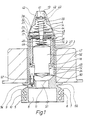
- a dosing apparatus is shown provided with the general reference number 1.
- This apparatus comprises a housing 2 composed of two parts 3 and 4, which may be assembled in any known way, e.g. by ultrasonic welding.
- the housing 2 forms a mounting portion 5 surrounding a receiving aperture 6 adapted to receive the orifice of a bottle (not shown) or a similar device containing preferably a beverage.
- the mounting portion 5 is provided with slits 7, 8, 9 and 10, by means of which the dosing apparatus 1 may be fastened on the bottle in question in a manner not shown, e.g. by means of a sealing device.
- Said mounting slits 7-10 may of course be constructed in many different ways and be of many different shapes.
- first valve body 14 is disposed forming part of a first valve device provided with the general reference number 15.
- Said first valve device 15 also comprises a cylindrical displacement body 16 made of a magnetically activable material.
- Said cylindrical displacement body 16 is displaceably mounted in a cylindrical part of the housing 2 within the cavity 12. During its displacement the displacement body 16 is guided by means of circumferential guide rings 17, 18, shown most clearly in Fig. 3.
- These guide rings 17, 18 are each adapted to be received in a circumferential groove in the outer wall of the cylindrical displacement body 16 and are provided with a slit 19 permitting mounting of the guide rings 17, 18 by snap action.
- the guide rings 17, 18 are further shaped in such a manner that they comprise radially extending projections 20, 21, 22, and 23 located at a suitable mutual angular distance round the periphery of the guide rings 17, 18.
- Besides the guide rings 17, 18 are of such dimensions that substantially only these projections 20-23 extend beyond the wall of the displacement body 16, and the projections 20-23 moreover have such an extension, that by cooperation with the inner cylindrical wall 24 of the housing 2 they guide the cylindrical displacement body 16 in a substantially coaxial path relative to the housing 2.
- the displacement body 16 comprises two circumferential recesses 25, 26, of which the first one 25 is closest to the end, which is foremost in the mounting state, of the displacement body 16 and is adapted to be received by an annular connection member 27 with radially inwardly projecting parts, by means of which the cylindrical body 16 is connected with the first valve body 14 in a manner described more explicitly below.
- the annular connection member 27, more clearly shown in Fig. 2 has radially inwardly extending branches 28, 29, 30, 31 connected with an inner annular abutment portion 32 which defines an opening 33 for receiving the first valve body 14. As it appears from Fig.
- the annular connection member 27 as well as the annular abutment portion 32 comprise a slit 34 and 35, respectively, permitting the connection member 27 to be snapped in the displacement body 16 as well as the first valve body 14 to be snapped in the opening 33, the connection member 27 being made of a suitably firm material.
- connection member 27 The inner opening 33 of the connection member 27 is adapted to cooperate with a shaft part 36 on the first valve body 14.
- Said shaft part 36 has a circular cross-section dimensioned together with the inner opening 33 of the connection member 27 in such a manner that said two parts can be displaced axially relative to each other.
- the displacement of the shaft part 36 relative to the bearing portion 32 of the connection member 27 is at the back limited by a radially, protruding circumferential abutment collar 37 and at the front by a radially extending shoulder surface 38.
- the first valve body 14 forms an annular rod portion 39 extending to a head 40, which in a circumferential groove 41 carries a sealing means 42 for cooperation with a circumferential, substantially radially extending valve seat 43 on the inner side of the housing 2 and adjacent to the outlet opening 13.
- the first valve body 14 is pressed into its closed position, in which the sealing means 42 about the valve seat 43, by means of a schematically shown biased spring 44 functioning between the head 40 of the valve body 14 and a support disc 45 fastened to the inner side of the housing 2.
- Said support disc 45 may be of many different shapes, e.g. a shape corresponding to the connection member 27 so that it may partly be snapped in the inner of the housing 2 and partly be snapped round the rod portion 39 of the valve body 14. Simultaneously the support disc 45 contribute to the guidance of the first valve body 14 during its axial displacement.
- the shaft part 36 of the first valve body 14 is placed relative to the remaining parts of said first valve body 14 in such a way that the displacement body 16 with the attached connection member 27 is at the end of the shaft part 36 closest to the shoulder surface 38 when the first valve body 14 is in closed position, and the displacement body 16 is in its inactivated position i.e. displaced as far ahead as possible relative to the inner cylindrical wall 24 of the housing 2.
- the said second internal circumferential recess 26 of the displacement body 16 is adapted to fasten one end of a spiral spring 46, the other end of which is connected with a second valve body 47 displaceably born within the back end of the displacement body 16 in the mounting position.
- the spring 46 is connected with the second valve body 47 in a circumferential groove 48.
- the second valve body 47 forms part of a second valve device provided with the general reference number 49 and adapted to close the inlet opening 11 by means of a circumferential sealing means 50 when pressing the sealing means 50 towards a valve seat 51 on the inner side of the housing 2.
- the second valve body 47 is shaped as a solid of revolution and is coaxial with the first valve body 14 as well as with the cylindrical displacement body 16 and moreover with the inner cavity 12 of the housing 2. In the position shown in Fig. 1, the second valve body 47 abuts the rear circumferential abutment collar 37 of the first valve body 14, but by displacing the displacement body 16 the second valve body 47 is pushed away from the first valve body 14 and down to cooperate with the valve seat 51.
- Said springs 44 and 46 -which actuate the first valve body 14 and the second valve body 47, respectively, and the cooperating parts of the first valve body 14 and the second valve body 47 as well as the displacement body 16 - are formed in such a way that the first valve body 14 remains in closed position until the second valve body 47 has been pushed into its closed position during the movement of the displacement body 16 in axial direction down towards the inlet opening 11.
- the shaft part 36 of the first valve body 16 consequently has such an axial extension that the abutment portion 32 of the connection member 27 does not engage the collar part 37 before the second valve body 47 has reached its closed position during the axial movement of the displacement body 16 down towards the inlet opening 11.
- an air valve provided with the general reference number 54 is disposed in the wall of said housing 2.
- Said air valve 54 shown on a larger scale in Fig. 4, is located in a passage 55 extending through the wall of the housing 2.
- the air valve 54 comprises a cylindrical valve housing 56 with an external cross-section corresponding to the internal cross-section of the passage 55, so that it may be maintained and received in said passage 55 by a press fit.
- the valve housing 56 contains a displaceable valve body 57 having a circular cross-section.
- valve body 57 has a circumferential groove 58, in which a sealing ring 59 is located adapted to cooperate with an adjacent valve seat 60 formed on the valve housing 56 in such a way that by abutment against said housing 56 the seal 60 turns off the passage of air through the passage 55 and the inner cavity of the housing 56; through an opening 61 said cavity is connected to the inner cavity 12 of the dosing apparatus 1.
- a spiral spring 63 is disposed extending coaxially with the valve body 57 and being adapted to impart a preload to said valve body 57 into its closed position.
- the spring 63 is secured to an axially protruding pin 64 having a circumferential flange 65 on the valve body 57.
- the air valve 54 is located and dimensioned in such a way that during its opening movement, i.e. when the first valve body 14 is brought into open position and the second valve body 47 into closed position, the displacement body 16 presses the valve body 57 of the air valve 54 out of engagement with its valve seat 60, so that while the first valve body 14 is in open position the flow of air through the air valve 54 is made possible. Consequently, the valve body 57 of the air valve 54 extends in axial direction through the end of the housing 56 opposite the valve seat 60 in order to engage the displacement body 16 during its activation.
- the parts of the dosing apparatus 1 may be made of suitable plastic materials, preferably by spray welding.
- the inner cavity 12 has such a dimension that when the parts hereof are present it may hold a beverage in a quantity corresponding to a predetermined measure; said quantity may be adjusted by adapting the outer shapes of the valve bodies 14, 47 and by screwing in an adjustment part from the outside, e.g. in the front end of the dosing apparatus 1.
- the dosing apparatus 1 is secured to an open bottle, the orifice of which is received in the receiving aperture 6. If desired the securing may as mentioned by effected by means of a sealing device securing that the dosing apparatus 1 cannot be moved from the bottle without it be noticed.
- the bottle is turned upside down whereby liquid flows from the bottle into the inner cavity 12 of the dosing apparatus 1 through the inlet opening 11 until the cavity 12 is full.
- the dosing apparatus 1 is then led through an activation ring 52 activated in a well-known manner so that the displacement body 16 is actuated by an electromagnetic force, and as a result the displacement body 16 is displaced axially in a direction away from the position shown in Fig.
- the second valve body 47 is first brought into the position, in which it closes the inlet opening 11, and then the first valve body 14 is pulled out of engagement with its seat 43 and opens the outlet opening 13.
- its bottom end engages the valve body 57 of the air valve 54 and thus turns on the inflow of air through the air valve 54.
- the quantity in question of the beverage may flow out through the outlet opening 13 until the dosing apparatus 1 is completely empty.
- the air valve 54 equalizes the pressure in the cavity 12.
- the activation ring 52 is adjusted to actuate the displacement body 16 into open position, i.e.
- the activation of the valve body is interrupted, so that the displacement body 16 is capable of returning to the initial position shown in Fig. 1 During this movement, which if desired may be supported by an additional spring means, not shown, the first valve body 14 is first led into its closed position by means of the spring 44, and not until then does the second valve body 47 disengage its valve seat 51, so that the inflow of beverage from the bottle to the dosing apparatus 1 is again made possible.
- the air valve 54 automatically turns off the inflow of air by means of the spring 63.
- beverages may again flow into the inner of the dosing apparatus, and when it is filled, the dispensing process may take place again.
- the activation ring 52 may in a well-known manner be connected with a cash register and thus register the dispensing in question.
- the activation ring may be associated with a reader, and the dosing apparatus 1 may be provided with a code, e.g. a dash code (not shown). It is hereby made possible simultaneously with the registration of the dispensing in question also to register the type of the beverage.
- the activation ring 52 may be loosely connected with the cash register by suitable wires.
- the activation ring 52 may, however, also be a fixed ring, which if desired may be connected to a locking arrangement (not shown), which simultaneously with the activation of the activation ring 52 locks the dosing apparatus 1 with associated bottle, e.g. by engaging a recess 66 in connection with the mounting portion 5 of the housing 2. It is hereby ensured that the user does not remove the dosing apparatus 1 with associated bottle from the activation ring 52 before the dispensing is completely terminated.
- the second valve body 57 may e.g. be constructed with longitudinal grooves or recesses in the outer surface in order to secure that the beverage more easily passes this body and the displacement body 16.
Landscapes
- Engineering & Computer Science (AREA)
- Mechanical Engineering (AREA)
- Physics & Mathematics (AREA)
- Fluid Mechanics (AREA)
- General Physics & Mathematics (AREA)
- Devices For Dispensing Beverages (AREA)
- Lift Valve (AREA)
Applications Claiming Priority (4)
| Application Number | Priority Date | Filing Date | Title |
|---|---|---|---|
| DK501882 | 1982-11-11 | ||
| DK5018/82 | 1982-11-11 | ||
| DK1504/83 | 1983-04-05 | ||
| DK150483A DK155586B (da) | 1982-11-11 | 1983-04-05 | Doseringsapparat til udskaenkning af forudbestemte maengder af fortrinsvis en drikkevare fra en flaske |
Publications (2)
| Publication Number | Publication Date |
|---|---|
| EP0126739A1 EP0126739A1 (en) | 1984-12-05 |
| EP0126739B1 true EP0126739B1 (en) | 1988-01-20 |
Family
ID=26065840
Family Applications (1)
| Application Number | Title | Priority Date | Filing Date |
|---|---|---|---|
| EP83903536A Expired EP0126739B1 (en) | 1982-11-11 | 1983-11-04 | A dosing apparatus for dispensing predetermined quantities preferably of beverages from a bottle |
Country Status (6)
| Country | Link |
|---|---|
| US (1) | US4598845A (da) |
| EP (1) | EP0126739B1 (da) |
| JP (1) | JPS59501979A (da) |
| DE (1) | DE3375385D1 (da) |
| DK (1) | DK155586B (da) |
| WO (1) | WO1984001937A1 (da) |
Families Citing this family (20)
| Publication number | Priority date | Publication date | Assignee | Title |
|---|---|---|---|---|
| DE3509189C1 (de) * | 1985-03-14 | 1986-05-15 | Peter 3300 Braunschweig Albrecht | Vorrichtung zum dosierten Ausschenken und Registrieren von Fluessigkeiten |
| GB2186265B (en) * | 1986-02-10 | 1989-11-01 | Isoworth Ltd | Beverage dispensing apparatus |
| SE8700640L (sv) * | 1987-02-17 | 1988-08-18 | Akerlund & Rausing Ab | Forfarande och anordning for kontaminationsfri access till en forpackningsbehallares fyllgods |
| AT403904B (de) * | 1991-08-12 | 1998-06-25 | Kurt Artmann | Portioniervorrichtung |
| US5603430A (en) * | 1995-02-10 | 1997-02-18 | Dec International, Inc. | Beverage dispensing system with bottle identification mechanism |
| GB2304686A (en) * | 1995-09-09 | 1997-03-26 | Raymond Norreys Iles | Valves and liquid supply systems |
| DE60201094T2 (de) | 2001-01-24 | 2005-10-13 | Lindberg & Jensen Aps | Dosiervorrichtung für einen Behälter |
| US8091735B2 (en) * | 2004-02-13 | 2012-01-10 | Intelligent Coffee Company, Llc | Liquid dispensing system |
| US7651015B2 (en) * | 2004-02-13 | 2010-01-26 | Intelligent Coffee Company, Llc | Liquid concentrate/extract beverage dispenser with replaceable concentrate/extract cartridge |
| BRPI0506804A (pt) | 2004-02-13 | 2007-05-29 | Intelligent Coffee Company L L | liberador de bebida em concentrado / extrato lìquido com cartucho de concentrado / extrato substituìvel |
| EP1598311B1 (en) * | 2004-05-18 | 2007-07-11 | Dannemose, Per Henrik | Dosing device for mounting on a container |
| US8196781B2 (en) * | 2005-01-07 | 2012-06-12 | Intelligent Coffee Company, Llc | Disposable pump |
| US7896202B2 (en) * | 2005-01-07 | 2011-03-01 | Shlomo Greenwald | Disposable integrated bag and pump |
| WO2007144002A1 (en) * | 2006-06-16 | 2007-12-21 | Wircon A/S | A pouring stopper |
| US8561851B1 (en) | 2007-03-23 | 2013-10-22 | Christopher A. Leonoff | Sports bottle with preloaded valve and methods |
| US20080314933A1 (en) * | 2007-03-23 | 2008-12-25 | Christopher Leonoff | Rapid flow bottle |
| WO2011074953A2 (en) * | 2009-12-16 | 2011-06-23 | Ipn Ip B.V. | Fluid dose-measuring device |
| ITPD20130041A1 (it) * | 2013-02-25 | 2014-08-26 | T T S S R L Tecno Trolley System | Corpo valvola di un dispositivo dosatore |
| US10723610B2 (en) * | 2016-09-26 | 2020-07-28 | Gate Cfv Solutions, Inc. | Magnetically controlled valve using a blocking device and a movement device |
| US10407293B2 (en) * | 2017-06-08 | 2019-09-10 | United States As Represented By The Secretary Of The Navy | Smart liquid dispenser system |
Family Cites Families (8)
| Publication number | Priority date | Publication date | Assignee | Title |
|---|---|---|---|---|
| US2314384A (en) * | 1939-07-24 | 1943-03-23 | Laval Separator Co De | Device for delivering measured quantities of liquid |
| US3243086A (en) * | 1964-11-27 | 1966-03-29 | George D Dousette | Liquid dispensing device having a trap chamber and valves therefor |
| GB1309775A (en) * | 1970-07-01 | 1973-03-14 | Kueckens A | Apparatus for diluting concentrates for drinks |
| US3666144A (en) * | 1970-12-11 | 1972-05-30 | Air Guard Control Canada Ltd | Aerosol dispensing apparatus having disc-shaped solenoid-actuated plunger |
| GB1364862A (en) * | 1971-05-13 | 1974-08-29 | Kennedy J | Devices for dispensing predtermined quantities of liquid |
| DE2548442C2 (de) * | 1975-10-29 | 1985-09-19 | Robert B. San Jose Calif. Dodds | Ausschankeinrichtung zur kontrollierten Abgabe von Flüssigkeiten aus unterscheidbaren, jeweils von Hand zu kippenden Behältern |
| US4180106A (en) * | 1977-09-06 | 1979-12-25 | Coetzee John C | Device for dispensing measured quantities of a liquid from a bottle |
| DE2932558C2 (de) * | 1979-08-10 | 1983-03-24 | DAGMA Deutsche Automaten- und Getränkemaschinen GmbH & Co KG, 2067 Reinfeld | Vorrichtung zum genauen Dosieren von Fluids schwankender Viskosität, insb. stark viskosen Flüssigkeiten |
-
1983
- 1983-04-05 DK DK150483A patent/DK155586B/da not_active IP Right Cessation
- 1983-11-04 WO PCT/DK1983/000105 patent/WO1984001937A1/en not_active Ceased
- 1983-11-04 JP JP58503619A patent/JPS59501979A/ja active Pending
- 1983-11-04 US US06/629,540 patent/US4598845A/en not_active Expired - Fee Related
- 1983-11-04 EP EP83903536A patent/EP0126739B1/en not_active Expired
- 1983-11-04 DE DE8383903536T patent/DE3375385D1/de not_active Expired
Also Published As
| Publication number | Publication date |
|---|---|
| JPS59501979A (ja) | 1984-11-29 |
| DK150483D0 (da) | 1983-04-05 |
| DK155586B (da) | 1989-04-24 |
| DE3375385D1 (en) | 1988-02-25 |
| DK150483A (da) | 1984-05-12 |
| WO1984001937A1 (en) | 1984-05-24 |
| EP0126739A1 (en) | 1984-12-05 |
| US4598845A (en) | 1986-07-08 |
Similar Documents
| Publication | Publication Date | Title |
|---|---|---|
| US4598845A (en) | Dosing apparatus for dispensing predetermined quantities preferably of beverages from a bottle | |
| US5255713A (en) | Valve with integral plastic spring for poppet | |
| US3446403A (en) | Dispenser | |
| GB2262152A (en) | Solenoid valve | |
| EP0191614A2 (en) | Improvements in valves for pressurised dispensing containers | |
| JP2003530279A (ja) | 液体用分配バルブ | |
| CN100363114C (zh) | 流体物质计量阀 | |
| JP2018100128A (ja) | 再充填不能エアロゾル弁 | |
| EP1598311B1 (en) | Dosing device for mounting on a container | |
| US5524864A (en) | Check valve made of plastic | |
| US3540624A (en) | Aerosol package having a combined actuator and overcap construction and method for making said construction | |
| GB2198117A (en) | Aerosol metering valve assembly | |
| US3550813A (en) | Hand-held dispenser for mixing fluids | |
| US4601411A (en) | Electromagnetic metering device having asymmetrical levers | |
| US2045926A (en) | Dispenser | |
| US6041967A (en) | Rapid connecting assembly for an aerosol can and a dispensing device | |
| US2504145A (en) | Drink dispenser and counter | |
| EP0583956B1 (en) | A tablet dispenser | |
| WO2004045778A1 (en) | Dispensing pump | |
| US6655556B1 (en) | Dispensing device intended to equip a container | |
| IL24302A (en) | Spray valve with protruding stem | |
| EP0010912B1 (en) | Improvements in and relating to ingredient containers for vending machines | |
| US3537620A (en) | Metering and dispensing device for liquids | |
| US4466559A (en) | Valves for controlling dispensation of fluid material | |
| CN111788125A (zh) | 流体产品分配器 |
Legal Events
| Date | Code | Title | Description |
|---|---|---|---|
| PUAI | Public reference made under article 153(3) epc to a published international application that has entered the european phase |
Free format text: ORIGINAL CODE: 0009012 |
|
| AK | Designated contracting states |
Designated state(s): BE DE FR GB NL SE |
|
| 17P | Request for examination filed |
Effective date: 19840706 |
|
| RAP1 | Party data changed (applicant data changed or rights of an application transferred) |
Owner name: HARTWALL LTD. |
|
| RIN1 | Information on inventor provided before grant (corrected) |
Inventor name: OZDEMIR NAZMI |
|
| GRAA | (expected) grant |
Free format text: ORIGINAL CODE: 0009210 |
|
| AK | Designated contracting states |
Kind code of ref document: B1 Designated state(s): BE DE FR GB NL SE |
|
| REF | Corresponds to: |
Ref document number: 3375385 Country of ref document: DE Date of ref document: 19880225 |
|
| ET | Fr: translation filed | ||
| PLBE | No opposition filed within time limit |
Free format text: ORIGINAL CODE: 0009261 |
|
| STAA | Information on the status of an ep patent application or granted ep patent |
Free format text: STATUS: NO OPPOSITION FILED WITHIN TIME LIMIT |
|
| 26N | No opposition filed | ||
| PGFP | Annual fee paid to national office [announced via postgrant information from national office to epo] |
Ref country code: SE Payment date: 19891024 Year of fee payment: 7 |
|
| PG25 | Lapsed in a contracting state [announced via postgrant information from national office to epo] |
Ref country code: GB Effective date: 19891104 |
|
| PG25 | Lapsed in a contracting state [announced via postgrant information from national office to epo] |
Ref country code: BE Effective date: 19891130 |
|
| BERE | Be: lapsed |
Owner name: HARTWALL LTD Effective date: 19891130 |
|
| PG25 | Lapsed in a contracting state [announced via postgrant information from national office to epo] |
Ref country code: NL Effective date: 19900601 |
|
| GBPC | Gb: european patent ceased through non-payment of renewal fee | ||
| NLV4 | Nl: lapsed or anulled due to non-payment of the annual fee | ||
| PG25 | Lapsed in a contracting state [announced via postgrant information from national office to epo] |
Ref country code: FR Effective date: 19900731 |
|
| PG25 | Lapsed in a contracting state [announced via postgrant information from national office to epo] |
Ref country code: DE Effective date: 19900801 |
|
| REG | Reference to a national code |
Ref country code: FR Ref legal event code: ST |
|
| PG25 | Lapsed in a contracting state [announced via postgrant information from national office to epo] |
Ref country code: SE Effective date: 19901105 |
|
| EUG | Se: european patent has lapsed |
Ref document number: 83903536.7 Effective date: 19910705 |