EP0126843B1 - Vorrichtung zum Reproduzieren einer Bezugsposition - Google Patents
Vorrichtung zum Reproduzieren einer Bezugsposition Download PDFInfo
- Publication number
- EP0126843B1 EP0126843B1 EP84101254A EP84101254A EP0126843B1 EP 0126843 B1 EP0126843 B1 EP 0126843B1 EP 84101254 A EP84101254 A EP 84101254A EP 84101254 A EP84101254 A EP 84101254A EP 0126843 B1 EP0126843 B1 EP 0126843B1
- Authority
- EP
- European Patent Office
- Prior art keywords
- scanning
- reference mark
- scale
- measuring scale
- movement
- Prior art date
- Legal status (The legal status is an assumption and is not a legal conclusion. Google has not performed a legal analysis and makes no representation as to the accuracy of the status listed.)
- Expired
Links
Images


Classifications
-
- G—PHYSICS
- G01—MEASURING; TESTING
- G01D—MEASURING NOT SPECIALLY ADAPTED FOR A SPECIFIC VARIABLE; ARRANGEMENTS FOR MEASURING TWO OR MORE VARIABLES NOT COVERED IN A SINGLE OTHER SUBCLASS; TARIFF METERING APPARATUS; MEASURING OR TESTING NOT OTHERWISE PROVIDED FOR
- G01D5/00—Mechanical means for transferring the output of a sensing member; Means for converting the output of a sensing member to another variable where the form or nature of the sensing member does not constrain the means for converting; Transducers not specially adapted for a specific variable
- G01D5/26—Mechanical means for transferring the output of a sensing member; Means for converting the output of a sensing member to another variable where the form or nature of the sensing member does not constrain the means for converting; Transducers not specially adapted for a specific variable characterised by optical transfer means, i.e. using infrared, visible, or ultraviolet light
- G01D5/32—Mechanical means for transferring the output of a sensing member; Means for converting the output of a sensing member to another variable where the form or nature of the sensing member does not constrain the means for converting; Transducers not specially adapted for a specific variable characterised by optical transfer means, i.e. using infrared, visible, or ultraviolet light with attenuation or whole or partial obturation of beams of light
- G01D5/34—Mechanical means for transferring the output of a sensing member; Means for converting the output of a sensing member to another variable where the form or nature of the sensing member does not constrain the means for converting; Transducers not specially adapted for a specific variable characterised by optical transfer means, i.e. using infrared, visible, or ultraviolet light with attenuation or whole or partial obturation of beams of light the beams of light being detected by photocells
- G01D5/36—Forming the light into pulses
-
- G—PHYSICS
- G01—MEASURING; TESTING
- G01D—MEASURING NOT SPECIALLY ADAPTED FOR A SPECIFIC VARIABLE; ARRANGEMENTS FOR MEASURING TWO OR MORE VARIABLES NOT COVERED IN A SINGLE OTHER SUBCLASS; TARIFF METERING APPARATUS; MEASURING OR TESTING NOT OTHERWISE PROVIDED FOR
- G01D3/00—Indicating or recording apparatus with provision for the special purposes referred to in the subgroups
- G01D3/06—Indicating or recording apparatus with provision for the special purposes referred to in the subgroups with provision for operation by a null method
- G01D3/063—Comparing the measuring value with a reference value which periodically or incidentally scans the measuring range
-
- G—PHYSICS
- G01—MEASURING; TESTING
- G01D—MEASURING NOT SPECIALLY ADAPTED FOR A SPECIFIC VARIABLE; ARRANGEMENTS FOR MEASURING TWO OR MORE VARIABLES NOT COVERED IN A SINGLE OTHER SUBCLASS; TARIFF METERING APPARATUS; MEASURING OR TESTING NOT OTHERWISE PROVIDED FOR
- G01D5/00—Mechanical means for transferring the output of a sensing member; Means for converting the output of a sensing member to another variable where the form or nature of the sensing member does not constrain the means for converting; Transducers not specially adapted for a specific variable
- G01D5/26—Mechanical means for transferring the output of a sensing member; Means for converting the output of a sensing member to another variable where the form or nature of the sensing member does not constrain the means for converting; Transducers not specially adapted for a specific variable characterised by optical transfer means, i.e. using infrared, visible, or ultraviolet light
- G01D5/32—Mechanical means for transferring the output of a sensing member; Means for converting the output of a sensing member to another variable where the form or nature of the sensing member does not constrain the means for converting; Transducers not specially adapted for a specific variable characterised by optical transfer means, i.e. using infrared, visible, or ultraviolet light with attenuation or whole or partial obturation of beams of light
- G01D5/34—Mechanical means for transferring the output of a sensing member; Means for converting the output of a sensing member to another variable where the form or nature of the sensing member does not constrain the means for converting; Transducers not specially adapted for a specific variable characterised by optical transfer means, i.e. using infrared, visible, or ultraviolet light with attenuation or whole or partial obturation of beams of light the beams of light being detected by photocells
- G01D5/347—Mechanical means for transferring the output of a sensing member; Means for converting the output of a sensing member to another variable where the form or nature of the sensing member does not constrain the means for converting; Transducers not specially adapted for a specific variable characterised by optical transfer means, i.e. using infrared, visible, or ultraviolet light with attenuation or whole or partial obturation of beams of light the beams of light being detected by photocells using displacement encoding scales
- G01D5/3473—Circular or rotary encoders
Definitions
- the invention relates to a device according to the preamble of claim 1.
- a measuring system in a machine which enables a reference position to be determined when the machine slide is clamped on the machine bed.
- the slide must be moved to the position that will later be declared the reference position to zero.
- the carriage is clamped on the machine bed.
- the scanning plate is then moved relative to the scale until a reference mark occurs.
- the electronic counter of the measuring device is set to zero.
- the clamp for the machine parts can be released again and the slide can be moved into the desired position.
- the position of the reference mark thus represents the reference position for the further operations.
- the reference position should be known.
- a return movement of the robot from its current position to the original starting position is generally not possible because, for example, a tool is currently in use.
- the invention is therefore based on the object of specifying a device for reproducing a reference position, which eliminates the disadvantages of the known methods and devices and makes it possible to determine a reference position after interrupted measurements and movements from unknown instantaneous positions without moving the objects to be measured.
- the proposed device allows the reproduction of a reference position after interrupted measurements and movements from unknown instantaneous positions in a simple and quick manner, without the objects to be measured having to be moved.
- Such an object to be measured in the form of a tool can thus remain in engagement with the workpiece in the event of an interruption in the measuring process due to a fault, so that the interrupted machining process can be resumed immediately after the fault has been eliminated and the reference position has been determined. Retracting the tool from the point of engagement on the workpiece and precisely restarting this point of engagement is time consuming and difficult and can lead to damage to the workpiece.
- this device enables program-controlled checks of the respective reference positions between individual work processes, as a result of which the operational safety of such systems is considerably increased.
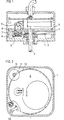
- the angle measuring device shown in Figure 1 has a housing 1 which is fastened in the housing of an industrial robot, not shown.
- a shaft 2 which is rotatably mounted in the housing 1, projects into the housing 1 and carries there a disk 3 with an incremental division 4 in the form of a grid.
- the incremental division 4 is scanned electrically.
- a second disk 5 is provided, which is also rotatably mounted on the shaft 2.
- the second disc 5 In the normal operating state, the second disc 5 is stationary, so that the lighting device 6 with condenser 7, scanning plate 8 and photo elements 9 fastened in it is also stationary and when the indexing disc 3 rotates, its movement by modulation of the one passing through the grating 4 and the scanning plate 8 Luminous flux is detected in a known manner by the photo elements 9 and is counted as an measured value in an electronic counter Z.
- the housing 1 is fixed in the housing A of the industrial robot, and the shaft 2 is fixedly connected to a handling module, for example a gripper B (see FIG. 3).
- a handling module for example a gripper B (see FIG. 3).
- the rotations that the gripper B executes are detected by the measuring device and passed on to an evaluation device Z for measuring or control purposes.
- reference marks are provided along the graduation track (as described, for example, in DE-OS-1 673 887 mentioned at the beginning or also in DE-PS-2 952 106).
- the gripper B is rotated until one of the reference marks is reached. This position is declared "zero", or another numerical value that has been previously defined or determined by a program is set in the counter Z there. During the subsequent work movements of the robot, this value selected at the beginning is the reference basis.
- the adjustment to the reference base can be done in the manner described in DE-OS-1 673 887 on page 14 above.
- the measured value pending when the fault occurs is lost, including the reference to the starting position.
- the tool of the gripper B since in the event of a malfunction the tool of the gripper B is currently engaged, it is not possible, as at the beginning of the working cycle, to rotate the gripper B until the original reference mark is detected by the scanning device.
- the measuring device is equipped with a drive motor 10.
- the drive motor 10 has a pinion 11 which meshes in an external toothing 12 of the disk 5 (FIG. 2).
- the drive motor 10 is activated and rotates the disk 5 via the gear 11/12 until the scanning device consisting of the lighting device 6, condenser 7, scanning plate 8 and photo elements 9 passes over a reference mark.
- the counter is reset to "zero" or the other selected value by the reference marks, the drive motor 10 is switched off and the disk 5 returns to the position in the event of a fault.
- the increments of the grating division 4 are counted and the distance of the current position from the reference position is known again.
- the invention can be carried out in a particularly advantageous manner with a device according to FIGS. 3 to 5.
- a shaft 32 is supported, among other things, which carries a disk 33 with an incremental grating 34 (see also FIG. 5).
- the shaft 32 carries a further disk 35 on which a scanning plate 38 is attached.
- the disk 35 is rotatably mounted on the shaft 32 and has a structure on its upper side facing away from the partial disk 33, which is provided with a switching arm 351 and a fork 352.
- An eccentric 311 engages between the arms of the fork 352 and sits on the axis of a drive motor 310.
- the drive motor 310 is fixed in place in the housing 31 in a holder 30.
- the illumination device 36, the condenser 37 and the photo elements 39 for scanning the grating division 34 and the reference marks R, to R n are likewise arranged in a stationary manner in the housing 31.
- the disc 35 In the idle state, the disc 35 is adjusted in position by a stop 353. The disc 35 has this position in the normal operating state.
- the normal function runs as described for Figures 1 and 2.
- a field of a certain size is illuminated by the lighting device 36 and the condenser 37.
- the arrangement of the reference marks R to R n and the photo elements 39 are matched to the size of this light field.
- a series of reference marks R i to R n are provided along the grating 34, which are arranged on a concentric track.
- the individual reference marks R, to R n are provided with code marks C, to C n and thus numbered, so to speak.
- the code mark Ci characterizes the distance of the associated reference mark Ri from a specific zero point of the grating division 34.
- the distribution of the reference marks R, to R n is dimensioned such that the reference mark R, exactly 100 grating graduation marks from the zero point of the division is removed, the reference mark R 2 exactly 200 grating marks etc. With a grating constant of 40 .mu.m this means that a reference mark Ri is arranged every 4 mm.
- the size of the illuminated field is designed such that one of the reference marks R 1 to R, and the associated code marks C 1 to C, lies within this illuminated field at each position of the index plate 33.
- the second of the rotatable disks 35 with the scanning plate 38 only has to be pivoted by a maximum of 4 mm in order to reliably scan one of the reference marks R 1 to R n and the code mark located at the reference marks.
- the counter Z is then set to the numerical value which is determined by the code mark Ci of the scanned reference mark Ri. From this value, the grid lines of the division 34 are counted during the pivoting back movement of the disk 35 until the disk 35 has reached its starting position - fixed by the stop 353.
- the instantaneous position in relation to the reference position has now been determined again and is represented as the measured value which results from the reference mark position (determined - by the code mark) and the count value of the grating lines of the graduation 34 superimposed on this, which also occurs when the scanning plate 38 moves back the disc 35 was determined.
- the vibration-sensitive lighting device 36 does not have to be moved during this process and will therefore have a longer service life. Adjustment problems do not occur because of the unchangeable position of the lighting device 36.
- the pivoting movement of the disk 35 is carried out by a drive motor 310, on the axis of which an eccentric 311 is seated.
- the eccentric 311 lies between the arms of a fork 352, which forms a structure on the top of the disk 35.
- a spring 354 supports the pivoting back and secures the exact contact at the stop 353.
- a switch 355 is actuated by a switching arm 351 on the upper structure of the disk 35, which stops the drive motor 310.
- the drive motor 310 has a small time constant, so that one revolution of the eccentric 311, that is to say also a complete pivoting movement of the disk 35, is completed within a tenth of a second.
- the measuring device described above works so quickly that not only can the reference position be reproduced safely in the event of malfunctions, but in the case of such a "calibration step" of only a tenth of a second, robots can easily pass such "calibration steps" from the program between the individual work processes provide controlled, which significantly increases the operational safety of such systems.
- the angle measuring device shown in longitudinal section in FIG. 6 has a housing G which is attached to a measuring object 0, for example to a housing of an industrial robot (not shown).
- a first shaft W is rotatably supported by means of the bearing L and carries a graduated disk T with an incremental graduation and with reference marks absolutely assigned to the incremental graduation.
- the incremental graduation and the reference marks of the graduated disk T are light-electrically scanned by a scanning unit AE fastened in the housing G, which has a lighting unit BE with a condenser CD, a scanning plate AP and photo elements P on a board PL fastened in the housing G.
- the rotation of the graduated disk T is detected by the modulation of the light flux passing through the divisions of the graduated disk T and the scanning plate AP in a known manner by the photoelements P, whose periodic scanning signals are used by a counter to determine a measured value for the relative position of the graduated disk T with respect to the scanning unit AE be forwarded.
- the first shaft W is connected via a driver clutch K, to a second shaft W 2 , which is likewise mounted in the interior of the housing G by means of bearing L 2 and from the housing G for attachment to the other rotatable object O to be measured 2 , for example on a gripper of the industrial robot, protrudes.
- the driver clutch K consists of a connecting hub F 1 , which is fixed on the shaft W, and a connecting hub F 2 , which is fixed on the shaft W 2 , and an annular disc RS.
- a connecting hub F 1 which is fixed on the shaft W
- a connecting hub F 2 which is fixed on the shaft W 2
- an annular disc RS At the periphery of the two connection hubs F 1 , F 2 , three stops S t , S 2, each offset by 120 ° to one another, protrude in the radial direction.
- the ring disk RS is arranged, which has on its periphery three bolts BZ offset by 120 ° to one another, which protrude in the axial direction from bores on both sides of the ring disk RS and with the stops S 1 , S 2 connecting hub F 1, F 2 are in contact with a rotation of the waves W l, W. 2
- the annular disc RS has no own bearing and is self-centering due to the symmetrical arrangement of the bolts BZ when the shafts W 1 , W 2 rotate and exerts on the bearings L 1 , L 2 of the shafts W 1 . W 2 no lateral force.
- the driver clutch K takes one predetermined direction of rotation of the rotatable object O 2 and thus the shaft W 2 via the bolts BZ in contact with each other of the ring disk RS and stops S 1 , S 2 of the connection hubs F 1 , F 2, the shaft W 1 with the indexing disk T with. If the predetermined direction of rotation of the shaft W 2 is reversed, the shaft W 1 is no longer taken along, since the bolts BZ of the ring disk RS and the stops S 2 of the connecting hub F 2 become out of contact.
- the clutch plate K 1 facing away from the shaft end of the shaft is W 1 via a slip clutch K 2 with a Coupled in the housing G drive motor M, which drives the shaft W 1 against the predetermined direction of rotation of the shaft W 2 .
- the two waves W 1, W 2 are thus fixed to each other so that the relative position of the two can be determined exactly by the angle measuring objects to be measured 2 0 0. 1
- the object O 2 to be measured is rotated before the start of a new measurement with the drive motor M acting until a reference mark is scanned.
- the counter is set to the value "zero" or to another numerical value that has been defined beforehand or determined by a program.
- the drive motor M is reversed when the shaft W 2 is stationary; the drive motor M rotates the shaft W 1 with the indexing disk T via the slip clutch K 2 in the reverse direction of rotation until the scanning unit AE scans the original reference mark again, so that the counter is reset to the original value.
- the drive motor M is then reversed in the original direction of rotation and the shaft W 1 with the indexing disk T is turned back until the stops S 1 of the connection hub F 1 come into contact with the bolts BZ of the ring disk RS, so that the shaft W 1 and the indexing disk T once again have the current position when the fault occurred.
- the driving clutch K 1 has bolts BZ and stops S 1 , S 2 which are offset by 120 ° relative to each other, and thus a relative movement of the shaft W 1 with respect to the shaft W 2 is only possible within an angle ⁇ 240 ° when reproducing the reference position
- At least two reference marks are required on the graduated disk T to reproduce a lost reference position, which require coding in the form of code marks to differentiate between them, as described, for example, in DE-PS-2 952 106.
- a driver clutch K 1 'according to FIG. 7 which has a relative rotation of the shaft W 1 with respect to the shaft W 2 enables an angle of 360 °.
- the connecting hub F 2 'with the three stops S 2 ' offset from one another by 120 ° for connecting the shaft W 2 is identical to the connecting hub F 2 in FIG. 6 (FIG. 7b).
- connection hub F 1 'for connecting the shaft W 1 has, according to Figure 7b, 7c three radially and axially offset concentric stages U 1', U 2 ', U 3', wherein from each stage U 1 ', U 2', U 3 'a stop S 1 ' protrudes in the radial direction; the three stops S 1 'on the three stages U 1 ', U 2 ', U 3 ' are offset by 120 ° to each other.
- the annular disk RS' On the side facing the connection hub F 1 ', the annular disk RS' has three radially and axially offset concentric stages U 1 "U 2 ", U 3 ", with a bolt BZ from each stage U 1 ", U 2 “, U3” 1 'protrudes in the axial direction; the three bolts BZ 1 'on the steps U 1 ", U 2 “, U 3 “are offset from one another by 120 ° and come into contact with the respectively associated stops S 1 ' of the connection hub F 1 '.
- the stops S 2 'of the connecting hub F 2 ' and the associated bolts BZ 2 'of the ring disk RS' can be arranged on radially and axially offset concentric steps.
- the clutch K 1 can also be designed as a simple driver.
- the slip clutch K 2 can be designed as an eddy current brake, as a hydraulic clutch or as a magnetic driver.
- the Partial disk T can also be connected directly to the drive unit M.
Landscapes
- Physics & Mathematics (AREA)
- General Physics & Mathematics (AREA)
- Manipulator (AREA)
- Length Measuring Devices With Unspecified Measuring Means (AREA)
- Transmission And Conversion Of Sensor Element Output (AREA)
Description
- Die Erfindung bezieht sich auf eine Vorrichtung nach dem Oberbegriff des Anspruches 1.
- Es sind Verfahren zur Ermittlung von Bezugspositionen bekannt, bei denen relativ zueinander bewegliche Maschinen- oder Meßsystem-Bausteine aus einer Ausgangsposition bis zu einer Referenzmarke verfahren werden, um den bis dort zurückgelegten Wert zu ermitteln und zu speichern oder die Referenzmarke zur Bezugsposition mit dem Wert "Null" zu erklären. Ein solches Verfahren ist mit einem inkrementalen Längen- oder Winkelmeßsystem möglich, wie es in der DE-PS-1 964 381 beschrieben wird. Dieses Verfahren erfordert aber eine ungehinderte Relativbeweglichkeit der zu messenden Objekte, da Bauteile der Meßeinrichtung fest mit den zu messenden Objekten verbunden sind und gemeinsam mit diesen bis zu einer Referenzmarke verstellt werden müssen.
- Aus der DE-OS-1 673 887 ist ein Meßsystem bei einer Maschine bekannt, das bei auf dem Maschinenbett festgeklemmtem Maschinenschlitten die Ermittlung einer Bezugsposition ermöglicht. Als erstes muß dort der Schlitten in diejenige Position gefahren werden, die später als Bezugsposition zu Null erklärt werden soll. Danach wird der Schlitten auf dem Maschinenbett festgeklemmt. Anschließend wird die Abtastplatte relativ zum Maßstab verfahren, bis eine Referenzmarke auftritt. Bei Erreichen der Referenzmarke wird der elektronische Zähler der Meßeinrichtung auf Null gesetzt. Sodann kann die Klemmung für die Maschinenteile wieder gelöst und der Schlitten in die gewünschte Position eingefahren werden. Die Lage der Referenzmarke stellt also die Bezugsposition für die weiteren Arbeitsgänge dar.
- Die bekannten Verfahren zur Ermittlung einer als Ausgangslage definierten Bezugsposition - die vor den eigentlichen Arbeitsgängen erfolgt - sind mit den beschriebenen inkrementalen Meßeinrichtungen jedoch dann nicht mehr möglich, wenn bereits Arbeitsgänge erfolgt sind, und beispielsweise laufende Arbeitsgänge unterbrochen werden. Die Unterbrechung eines laufenden Arbeitsganges, beispielsweise bei einem Handhabungsautomaten - im allgemeinen als Industrieroboter bezeichnet - ist durch Stromausfall möglich. Der Roboter bleibt dann in seiner momentanen Position stehen; der auf seine ursprüngliche Bezugsposition bezogene, nach dem Stand der Technik ermittelte Meßwert geht aber durch den Stromausfall verloren, da auch die Messung unterbrochen wurde.
- Zur Fortführung des unterbrochenen Arbeitsganges müßte jedoch die Bezugsposition bekannt sein. Eine Rückbewegung des Roboters aus seiner Momentanposition in die ursprüngliche Ausgangslage scheidet aber in der Regel aus, weil beispielsweise gerade ein Werkzeug im Eingriff ist.
- Der Erfindung liegt daher die Aufgabe zugrunde, eine Vorrichtung zum Reproduzieren einer Bezugsposition anzugeben, die die Nachteile der bekannten Verfahren und Vorrichtungen beseitigt und es ermöglicht, nach unterbrochenen Messungen und Bewegungen aus unbekannten Momentanpositionen ohne Bewegung der zu messenden Objekte eine Bezugsposition zu ermitteln.
- Diese Aufgabe wird erfindungsgemäß durch die kennzeichnenden Merkmale des Anspruchs 1 gelöst.
- Weitere vorteilhafte Ausgestaltungen entnimmt man den abhängigen Ansprüchen.
- Die mit der Erfindung erzielten Vorteile bestehen insbesondere darin, daß die vorgeschlagene Vorrichtung auf einfache und schnelle Weise die Reproduktion einer Bezugsposition nach unterbrochenen Messungen und Bewegungen aus unbekannten Momentanpositionen erlaubt, ohne daß die zu messenden Objekte bewegt werden müssen. Ein solches zu messendes Objekt in Form eines Werkzeugs kann somit bei einer Unterbrechung des Meßvorgangs durch eine Störung im Eingriff am Werkstück verbleiben, so daß nach Behebung der Störung und Ermittlung der Bezugsposition der unterbrochene Bearbeitungsvorgang unverzüglich wieder fortgesetzt werden kann. Ein Zurückziehen des Werkzeugs von der Eingriffsstelle am Werkstück und ein erneutes genaues Wiederanfahren dieser Eingriffsstelle ist zeitaufwendig und schwierig und kann zu Beschädigungen des Werkstücks führen.
- Ferner ermöglicht diese Vorrichtung beispielsweise bei Robotern programmgesteuerte Überprüfungen der jeweiligen Bezugspositionen zwischen einzelnen Arbeitsabläufen, wodurch die Betriebssicherheit derartiger Systeme erheblich erhöht wird.
- Mit Hilfe von Zeichnungen soll anhand von Ausführungsbeispielen die Erfindung näher erläutert werden.
- Es zeigen
- Figur 1 ein Winkelmeßgerät, Schnittdarstellung,
- Figur 2 eine Draufsicht auf ein Gerät gemäß
- Figur 1, Schnittdarstellung,
- Figur 3 eine Variante eines Winkelmeßgerätes, Schnittdarstellung,
- Figur 4 einen Schnitt entlang der Linie A - B gemäß Figur 3,
- Figur 5 einen Schnitt entlang der Linie C - D gemäß Figur 3 als Sicht auf einen Teilscheibenausschnitt,
- Figur 6 eine Winkelmeßeinrichtung im Längsschnitt und
- Figur 7 eine Mitnehmerkupplung im Längsschnitt und in zwei Ansichten.
- Die in Figur 1 dargestellte Winkelmeßeinrichtung weist ein Gehäuse 1 auf, das im Gehäuse eines nicht dargestellten Industrieroboters befestigt ist. Eine im Gehäuse 1 drehbar gelagerte Welle 2 ragt in das Gehäuse 1 hinein und trägt dort eine Scheibe 3 mit einer Inkrementalteilung 4 in Form eines Gitters. Die Inkrementalteilung 4 wird lichtelektrisch abgetastet. Zu diesem Zweck ist eine zweite Scheibe 5 vorgesehen, die ebenfalls drehbar auf der Welle 2 gelagert ist. Im normalen Betriebszustand steht die zweite Scheibe 5 still, so daß die in ihr befestigte Beleuchtungseinrichtung 6 mit Kondensor 7, Abtastplatte 8 und Fotoelementen 9 ebenfalls ortsfest ist und bei Drehung der Teilscheibe 3 deren Bewegung durch Modulation des durch die Gitterteilung 4 und die Abtastplatte 8 hindurchtretenden Lichtstromes in bekannter Weise von den Fotoelementen 9 erfaßt und in einem elektronischen Zähler Z als Meßwert gezählt wird.
- Da also die zweite Scheibe 5 im allgemeinen zusammen mit dem Gehäuse 1 still steht, können auf diese Weise Drehbewegungen der Welle 2 - die die Teilscheibe 3 trägt - exakt ermittelt werden.
- In einem Industrieroboter ist das Gehäuse 1 fest im Gehäuse A des Industrieroboters befestigt, und die Welle 2 ist fest mit einem Handhabungsbaustein, beispielsweise einem Greifer B verbunden (s. Fig. 3).
- Die Drehungen, die der Greifer B ausführt, werden von der Meßeinrichtung erfaßt und zu Meß- oder Steuerzwecken an eine Auswerteeinrichtung Z weitergeleitet.
- Um bei derartigen inkrementalen Meßvorrichtungen eine Bezugsbasis zu gewinnen, sind entlang der Teilungsspur Referenzmarken vorgesehen (wie beispielsweise in der eingangs erwähnten DE-OS-1 673 887 oder auch der DE-PS-2 952 106 beschrieben). Vor Beginn eines Bearbeitungszyklus, also vor Beginn einer neuen Messung wird der Greifer B solange verdreht, bis eine der Referenzmarken erreicht ist. Diese Position wird zu "Null" erklärt, oder es wird dort ein anderer, vorher festgelegter oder durch ein Programm bestimmter Zahlenwert in den Zähler Z gesetzt. Während der nachfolgenden Arbeitsbewegungen des Roboters ist dieser eingangs gewählte Wert die Bezugsbasis. Das Einstellen auf die Bezugsbasis kann in der Weise geschehen, wie es in der DE-OS-1 673 887 auf Seite 14 oben beschrieben ist.
- Wenn nun während eines Bearbeitungszyklus eine Störung, etwa infolge einer Stromunterbrechung, auftritt, so muß der Arbeitsgang unterbrochen werden, was natürlich auch die Messung unterbricht.
- Bei Stromunterbrechung ist der beim Auftreten der Störung anstehende Meßwert verlorengegangen, also auch der Bezug auf die Ausgangsposition. Da jedoch im Störungsfall das Werkzeug des Greifers B in dar Regel gerade im Eingriff ist, kann nicht, wie zu Beginn des Arbeitszyklus, der Greifer B solange verdreht werden, bis von der Abtasteinrichtung - die ursprüngliche Referenzmarke erfaßt wird.
- Mit der erfindungsgemäßen Vorrichtung kann jedoch auch in diesem Falle die Bezugslage wieder hergestellt werden. Hierzu ist die Meßeinrichtung mit einem Antriebsmotor 10 ausgerüstet. Der Antriebsmotor 10 weist ein Ritzel 11 auf, das in einer Außenverzahnung 12 der Scheibe 5 kämmt (Fig. 2). Im Falle einer Störung wird der Antriebsmotor 10 angesteuert und verdreht über das Getriebe 11/12 die Scheibe 5 soweit, bis die Abtasteinrichtung bestehend aus Beleuchtungseinrichtung 6, Kondensor 7, Abtastplatte 8 und Fotoelementen 9 eine Referenzmarke überfährt. Durch die Referenzmarken wird der Zähler wieder auf "Null" oder auf den anderen gewählten Wert gesetzt, der Antriebsmotor 10 wird abgeschaltet und die Scheibe 5 kehrt in die Position beim Störfall zurück. Dabei werden die Inkremente der Gitterteilung 4 gezählt, und die Entfernung der Momentanposition von der Bezugsposition ist wieder bekannt.
- Während dieses Vorganges steht der Roboter still. Gehäuse 1, Welle 2 und Teilscheibe 3 bewegen sich nicht.
- Im Anschluß an dieses Reproduzieren einer Bezugsposition kann der Arbeitszyklus fortgesetzt werden.
- In besonders vorteilhafter Weise läßt sich die Erfindung mit einer Vorrichtung gemäß Figur 3 - Figur 5 durchführen.
- In einem Gehäuse 31 ist unter anderem eine Welle 32 gelagert, die eine Scheibe 33 mit einer inkrementalen Gitterteilung 34 trägt (siehe auch Fig. 5). Im Gehäuseinnern trägt die Welle 32 eine weitere Scheibe 35, an der eine Abtastplatte 38 angebracht ist. Die Scheibe 35 ist auf der Welle 32 drehbar gelagert und trägt an ihrer der Teilscheibe 33 abgewandten Oberseite einen Aufbau, der mit einem Schaltarm 351 und einer Gabel 352 versehen ist. Zwischen den Armen der Gabel 352 greift ein Exzenter 311 an, der auf der Achse eines Antriebsmotors 310 sitzt. Der Antriebsmotor 310 ist ortsfest im Gehäuse 31 in einer Halterung 30 befestigt. Die Beleuchtungseinrichtung 36, der Kondensor 37 und die Fotoelemente 39 zur Abtastung der Gitterteilung 34 und der Referenzmarken R, bis Rn sind ebenfalls ortsfest im Gehäuse 31 angeordnet. Im Ruhezustand ist die Scheibe 35 durch einen Anschlag 353 in ihrer Lage justiert. Diese Lage hat die Scheibe 35 im normalen Betriebszustand inne. Die normale Funktion läuft wie zu den Figuren 1 und 2 beschrieben ab.
- Im Störfall kann das Reproduzieren einer Bezugsposition hier jedoch sehr schnell ablaufen.
- Durch die Beleuchtungseinrichtung 36 und den Kondensor 37 wird ein Feld mit bestimmter Größe ausgeleuchtet. Auf die Größe dieses Leuchtfeldes sind die Anordnung der Referenzmarken R, bis Rn und die Fotoelemente 39 abgestimmt. Wie aus Figur 5 ersichtlich ist, ist entlang der Gitterteilung 34 eine Reihe von Referenzmarken Ri bis Rn vorgesehen, die auf einer konzentrischen Spur angeordnet sind. Die einzelnen Referenzmarken R, bis Rn sind mit Codemarken C, bis Cn versehen und damit sozusagen numeriert. Die Codemarke Ci kennzeichnet den Abstand der zugehörigen Referenzmarke Ri von einem bestimmten Nullpunkt der Gitterteilung 34. Die Verteilung der Referenzmarken R, bis Rn ist so bemessen, daß die Referenzmarke R, genau 100 Gitterteilstriche vom Nullpunkt der Teilung entfernt ist, die Referenzmarke R2 genau 200 Gitterteilstriche usw.. Bei einer Gitterkonstanten von 40 um bedeutet das, daß alle 4 mm eine Referenzmarke Ri angeordnet ist.
- Die Größe des ausgeleuchteten Feldes ist so ausgelegt, daß bei jeder Stellung der Teilscheibe 33 eine der Referenzmarken R1 bis R, und die zugehörigen Codemarken C1 bis C, innerhalb dieses ausgeleuchteten Feldes liegt.
- Im Störfalle muß also die zweite der drehbaren Scheiben 35 mit der Abtastplatte 38 lediglich um einen Weg von maximal 4 mm verschwenkt werden, um mit Sicherheit eine der Referenzmarken R1 bis Rn und die jeweils bei den Referenzmarken befindliche Codemarke abzutasten. An der Referenzmarke Ri wird dann der Zähler Z auf den Zahlenwert gesetzt, der durch die Codemarke Ci der abgetasteten Referenzmarke Ri festgelegt ist. Von diesem Wert aus werden bei der Rückschwenkbewegung der Scheibe 35 die Gitterstriche der Teilung 34 gezählt bis die Scheibe 35 ihre Ausgangslage - fixiert durch den Anschlag 353 - wieder erreicht hat. Die Momentanposition in Bezug auf die Bezugsposition ist nun wieder ermittelt und wird dargestellt als der Meßwert, der sich ergibt aus der Referenzmarkenposition (bestimmt - durch die Codemarke) und dem dieser überlagerten Zählwert der Gitterstriche der Teilung 34, der bei der Rückbewegung der Abtastplatte 38 mit der Scheibe 35 ermittelt wurde.
- Die erschütterungsempfindliche Beleuchtungseinrichtung 36 braucht bei diesem Vorgang nicht bewegt zu werden und wird daher eine längere Lebensdauer haben. Justierprobleme treten wegen der unveränderbaren Position der Beleuchtungseinrichtung 36 nicht auf.
- Die Schwenkbewegung der Scheibe 35 wird durch einen Antriebsmotor 310 vollzogen, auf dessen Achse ein Exzenter 311 sitzt. Der Exzenter 311 liegt zwischen den Armen einer Gabel 352, die auf der Oberseite der Scheibe 35 einen Aufbau bildet. Bei einer Motorumdrehung wird durch das Zusammenwirken des Exzenters 311 mit der Gabel 352 die Scheibe 35 um einen Weg von 4 mm geschwenkt und kehrt in ihre Ausgangslage am Anschlag 353 zurück. Eine Feder 354 unterstützt die Rückschwenkung und sichert die exakte Anlage am Anschlag 353. Im Moment der Rückkehr in die Ausgangslage wird durch einen Schaltarm 351 am oberseitigen Aufbau der Scheibe 35 ein Schalter 355 betätigt, der den Antriebsmotor 310 stillsetzt.
- Der Antriebsmotor 310 weist eine kleine Zeitkonstante auf, so daß eine Umdrehung des Exzenters 311, also auch eine vollständige Schwenkbewegung der Scheibe 35, innerhalb einer zehntel Sekunde vollzogen ist.
- Die vorbeschriebene Meßeinrichtung arbeitet derart schnell, daß nicht nur in Störungsfällen die Bezugsposition wieder sicher reproduziert werden kann, sondern bei einem solchen "Eichschritt" von nur einer zehntel Sekunde Dauer lassen sich bei Robotern ohne weiteres zwischen den einzelnen Arbeitsabläufen noch derartige "Eichschritte" vom Programm aus gesteuert vorsehen, was die Betriebssicherheit derartiger Systeme erheblich erhöht.
- Es liegt im Rahmen der Erfindung, auch andere Meßeinrichtungen, beispielsweise Längenmeßeinrichtungen derart zu gestalten.
- Ebenso bleibt es ins Belieben des Fachmannes gestellt, anstelle der Antriebsmotoren zur Verstellung der Abtasteinrichtung andere Antriebe zu wählen.
- Die in Figur 6 im Längsschnitt dargestellte Winkelmeßeinrichtung weist ein Gehäuse G auf, das an einem zumessenden Objekt 0, beispielsweise an einem Gehäuse eines nicht gezeigten Industrieroboters befestigt ist. Im Inneren des Gehäuses G ist eine erste Welle W, mittels Lager L, drehbar gelagert und trägt eine Teilscheibe T mit einer Inkrementalteilung und mit der Inkrementalteilung absolut zugeordneten Referenzmarken. Die Inkrementalteilung und die Referenzmarken der Teilscheibe T werden von einer im Gehäuse G befestigten Abtasteinheit AE lichtelektrisch abgetastet, die eine Beleuchtungseinheit BE mit einem Kondensor CD, eine Abtastplatte AP und Photoelemente P auf einer im Gehäuse G befestigten Platine PL aufweist. Die Drehung der Teilscheibe T wird durch die Modulation des durch die Teilungen der Teilscheibe T und der Abtastplatte AP hindurchtretenden Lichtstromes in bekannter Weise von den Photoelementen P erfaßt, deren periodische Abtastsignale einem Zähler zur Ermittlung eines Meßwertes für die Relativlage der Teilscheibe T bezüglich der Abtasteinheit AE zugeleitet werden.
- Die erste Welle W, mit der Teilscheibe T ist über eine Mitnehmerkupplung K, mit einer zweiten Welle W2 verbunden, die ebenfalls im Inneren des Gehäuses G mittels Lager L2 gelagert ist und aus dem Gehäuse G zur Befestigung am anderen zu messenden drehbaren Objekt O2, beispielsweise an einem Greifer des Industrieroboters, herausragt.
- Die Mitnehmerkupplung K, besteht aus einer Anschlußnabe F1, die auf der Welle W, befestigt ist, und aus einer Anschlußnabe F2, die auf der Welle W2 befestigt ist, sowie aus einer Ringscheibe RS. An der Peripherie der beiden Anschlußnaben F1, F2 ragen jeweils drei um 120° zueinander versetzte Anschläge St, S2 in radialer Richtung heraus. Zwischen den beiden Anschlußnaben F1, F2 ist die Ringscheibe RS angeordnet, die an ihrer Peripherie drei um 120° zueinander versetzte Bolzen BZ aufweist, die in axialer Richtung aus Bohrungen beidseitig der Ringscheibe RS herausragen und mit den Anschlägen S1, S2 der Anschlußnaben F1, F2 bei einer Drehung der Wellen Wl, W2 in Kontakt stehen. Die Ringscheibe RS besitzt keine eigene Lagerung und ist aufgrund der symmetrischen Anordnung der Bolzen BZ bei der Drehung der Wellen W1, W2 selbstzentrierend und übt auf die Lager L1, L2 der Wellen W1. W2 keine Querkraft aus.
- Die Mitnehmerkupplung K, nimmt bei einer vorgegebenen Drehrichtung des drehbaren Objekts O2 und damit der Welle W2 über die miteinander in Kontakt stehenden Bolzen BZ der Ringscheibe RS und Anschläge S1, S2 der Anschlußnaben F1, F2 die Welle W1 mit der Teilscheibe T mit. Bei einer Umkehrung der vorgegebenen Drehrichtung der Welle W2 wird die Welle W1 nicht mehr mitgenommen, da die Bolzen BZ der Ringscheibe RS und die Anschläge S2 der Anschlußnabe F2 außer Kontakt geraten. Um auch bei dieser umgekehrten Drehrichtung der Welle W2 einen Kontakt zwischen den Bolzen BZ der Ringscheibe RS und den Anschlägen S2 der Anschlußnabe F2 zu gewährleisten, ist das der Mitnehmerkupplung K1 abgewandte Wellenende der Welle W1 über eine Rutschkupplung K2 mit einem im Gehäuse G befestigten Antriebsmotor M gekoppelt, der die Welle W1 entgegen der vorgegebenen Drehrichtung der Welle W2 antreibt. In beiden Drehrichtungen des zu messenden Objekts 02 sind somit die beiden Wellen W1, W2 miteinander fest verbunden, so daß die Relativlage der beiden zu messenden Objekte 01, 02 durch die Winkelmeßeinrichtung exakt ermittelt werden kann.
- Um zur Messung der Relativlage der beiden Objekte 01, 02 eine bestimmte Bezugsposition zu gewinnen, wird vor Beginn einer neuen Messung das zu messende Objekt O2 bei wirkendem Antriebsmotor M solange verdreht, bis eine Referenzmarke abgetastet wird. Bei dieser Bezugsposition wird der Zähler auf den Wert "Null" oder auf einen anderen, vorher festgelegten oder durch ein Programm bestimmten Zahlenwert gesetzt.
- Wenn nun während eines Bearbeitungsvorganges und damit einer Messung eine Störung, etwa infolge einer Stromunterbrechung, auftritt, so wird der Arbeitsgang und damit auch die Messung des drehbaren Objekts O2 unterbrochen. Bei Stromunterbrechung sind der beim Auftreten der Störung vorhandene Meßwert und damit auch die Bezugsposition verlorengegangen. Da jedoch beim Auftreten des Störungsfalls das zu messende Objekt O2 in Form des Greifers des Industrieroboters in der Regel gerade im Eingriff ist, kann das Objekt O2 nicht, wie vor Beginn des Arbeitsgangs und der Messung, solange verdreht werden, bis die Abtasteinheit AE die ursprüngliche Referenzmarke abtastet.
- Zum Reproduzieren der Bezugsposition wird erfindungsgemäß bei stillstehender Welle W2 der Antriebsmotor M umgepolt; der Antriebsmotor M dreht die Welle W1 mit der Teilscheibe T über die Rutschkupplung K2 in der umgekehrten Drehrichtung, bis die Abtasteinheit AE wieder die ursprüngliche Referenzmarke abtastet, so daß der Zähler wieder auf den ursprünglichen Wert gesetzt wird. Anschließend wird der Antriebsmotor M erneut in die ursprüngliche Drehrichtung umgepolt und die Welle W1 mit der Teilscheibe T wieder bis zum Kontakt der Anschläge S1 der Anschlußnabe F1 mit den Bolzen BZ der Ringscheibe RS zurückgedreht, so daß die Welle W1 und die Teilscheibe T wieder die Momentanposition beim Auftreten der Störung innehaben. Bei dieser Rückkehr der Welle W1 und der Teilscheibe T von der ursprünglichen Referenzmarke zur Momentanposition beim Auftreten der Störung werden die Inkremente der Teilung der Teilscheibe T im Zähler gezählt, so daß der verlorengegangene Meßwert wiedergewonnen ist und der unterbrochene Arbeitsvorgang und Meßvorgang fortgesetzt werden können.
- Da die Mitnehmerkupplung K1 jeweils um 120° zueinander versetzte Bolzen BZ und Anschläge S1, S2 aufweist, und somit eine Relativbewegung der Welle W1 bezüglich der Welle W2 beim Reproduzieren der Bezugsposition nur innerhalb eines Winkels < 240° möglich ist, sind auf der Teilscheibe T zum Reproduzieren einer verlorengegangenen Bezugsposition mindestens zwei Referenzmarken erforderlich, die zur gegenseitigen Unterscheidung einer Codierung in Form von Codemarken bedürfen, wie sie beispielsweise in der DE-PS-2 952 106 beschrieben sind.
- Um zum Reproduzieren einer verlorengegangenen Bezugsposition mit nur einer Referenzmarke auf der Teilscheibe T auskommen zu können, die dann keiner Codierung mehr bedarf, wird eine Mitnehmerkupplung K1' gemäß Figur 7 vorgeschlagen, die eine Relativdrehung der Welle W1 bezüglich über der Welle W2 über einen Winkel von 360° hinaus ermöglicht. Die Anschlußnabe F2' mit den drei um 120° zueinander versetzten Anschlägen S2' zum Anschluß der Welle W2 ist mit der Anschlußnabe F2 der Figur 6 identisch (Figur 7b). Die Anschlußnabe F1' zum Anschluß der Welle W1 weist gemäß Figur 7b, 7c drei radial und axial abgesetzte konzentrische Stufen U1', U2', U3' auf, wobei aus jeder Stufe U1', U2', U3' ein Anschlag S1' in radialer Richtung herausragt; die drei Anschläge S1' auf den drei Stufen U1', U2', U3' sind um 120° zueinander versetzt. Bei der Ringscheibe RS' ragen aus der der Anschlußnabe F2' zugewandten Seite an der Peripherie drei um 120° zueinander versetzte Bolzen BZ2' in axialer Richtung heraus, die mit den Anschlägen S2' der Anschlußnabe F2' in Kontakt stehen (Figur 7b). Auf der der Anschlußnabe F1' zugewandten Seite weist die Ringscheibe RS' drei radial und axial abgesetzte konzentrische Stufen U1" U2", U3" auf, wobei aus jeder Stufe U1", U2", U3" ein Bolzen BZ1' in axialer Richtung herausragt; die drei Bolzen BZ1' auf den Stufen U1", U2", U3" sind um 120° zueinander versetzt und treten mit den jeweils zugehörigen Anschlägen S1' der Anschlußnabe F1' in Kontakt.
- In nicht dargestellter Weise können auch die Anschläge S2' der Anschlußnabe F2' und die zugehörigen Bolzen BZ2' der Ringscheibe RS' auf radial und axial abgesetzten konzentrischen Stufen angeordnet sein. Die Kupplung K1 kann auch als einfacher Mitnehmer ausgebildet sein.
- Die Rutschkupplung K2 kann als Wirbelstrombremse, als hydraulische Kupplung oder als magnetischer Mitnehmer ausgebildet sein. Die Teilscheibe T kann auch direkt mit der Antriebseinheit M verbunden sein.
Claims (15)
Priority Applications (1)
| Application Number | Priority Date | Filing Date | Title |
|---|---|---|---|
| AT84101254T ATE48032T1 (de) | 1983-03-26 | 1984-02-08 | Vorrichtung zum reproduzieren einer bezugsposition. |
Applications Claiming Priority (4)
| Application Number | Priority Date | Filing Date | Title |
|---|---|---|---|
| DE3311203 | 1983-03-26 | ||
| DE19833311203 DE3311203A1 (de) | 1983-03-26 | 1983-03-26 | Verfahren zum reproduzieren einer bezugsposition |
| DE3340866 | 1983-11-11 | ||
| DE19833340866 DE3340866A1 (de) | 1983-03-26 | 1983-11-11 | Wegmesseinrichtung |
Publications (3)
| Publication Number | Publication Date |
|---|---|
| EP0126843A2 EP0126843A2 (de) | 1984-12-05 |
| EP0126843A3 EP0126843A3 (en) | 1987-08-05 |
| EP0126843B1 true EP0126843B1 (de) | 1989-11-15 |
Family
ID=25809480
Family Applications (1)
| Application Number | Title | Priority Date | Filing Date |
|---|---|---|---|
| EP84101254A Expired EP0126843B1 (de) | 1983-03-26 | 1984-02-08 | Vorrichtung zum Reproduzieren einer Bezugsposition |
Country Status (3)
| Country | Link |
|---|---|
| US (1) | US4530155A (de) |
| EP (1) | EP0126843B1 (de) |
| DE (2) | DE3340866A1 (de) |
Families Citing this family (29)
| Publication number | Priority date | Publication date | Assignee | Title |
|---|---|---|---|---|
| DE3527546C1 (de) * | 1985-08-01 | 1986-10-02 | Dr. Johannes Heidenhain Gmbh, 8225 Traunreut | Vorrichtung zum Verbinden einer Positionsmesseinrichtung mit zwei relativ zueinander beweglichen Objekten |
| DD284772A5 (de) * | 1989-06-02 | 1990-11-21 | Veb Carl Zeiss Jena,Dd | Verfahren und anordnung zur ueberwachung eines winkel- oder laengenmesssystems an einer maschine |
| FR2668258B1 (fr) * | 1990-10-19 | 1994-05-13 | Cartier Systemes G | Capteur d'angle de rotation pour detecter le sens de rotation et/ou le nombre de tours effectues, et dispositif de direction assitee de vehicule comportant un tel capteur. |
| AT397717B (de) * | 1990-12-10 | 1994-06-27 | Rieder & Schwaiger Sentop | Drehgeber |
| US5435067A (en) * | 1991-06-06 | 1995-07-25 | Toshiba Kikai Kabushiki Kaisha | Method and apparatus for indexing attachment |
| DE4216234A1 (de) * | 1992-05-16 | 1993-11-18 | Karl Kessler | Meßmaschine |
| US5642297A (en) * | 1994-12-12 | 1997-06-24 | Gurley Precision Instruments, Inc. | Apparatus and method for measuring the kinematic accuracy in machines and mechanisms using absolute encoders |
| US6293022B1 (en) * | 1997-04-25 | 2001-09-25 | Kabushiki Kaisha Toyoda Jidoshokki Seisakusho | Mounting structure for wheel angle detector and rotation amount detector for vehicle wheel |
| EP1056989B1 (de) | 1998-02-21 | 2002-12-18 | Dr. Johannes Heidenhain GmbH | Verfahren zum betrieb eines positionsmesssystems und geeignetes positionsmesssystem hierzu |
| DE19820014A1 (de) | 1998-05-06 | 1999-11-11 | Heidenhain Gmbh Dr Johannes | Multiturn-Codedrehgeber |
| DE19831744A1 (de) * | 1998-07-15 | 2000-01-20 | Zeiss Carl Fa | Stellvorrichtung |
| US6417638B1 (en) * | 1998-07-17 | 2002-07-09 | Sensable Technologies, Inc. | Force reflecting haptic interface |
| DE59912617D1 (de) | 1998-08-01 | 2006-02-16 | Heidenhain Gmbh Dr Johannes | Rotatorische Positionsmesseinrichtung |
| DE19836003A1 (de) | 1998-08-08 | 2000-02-10 | Heidenhain Gmbh Dr Johannes | Verfahren zur Montage einer Positionsmeßeinrichtung und Positioniermittel zur Montage |
| DE19839028C1 (de) * | 1998-08-27 | 2000-02-10 | Asm Automation Sensorik Messte | Meßseil-Wegsensor |
| DE19904471B4 (de) | 1999-02-04 | 2011-03-31 | Dr. Johannes Heidenhain Gmbh | Drehgeber |
| DE19907326B4 (de) | 1999-02-20 | 2013-04-04 | Dr. Johannes Heidenhain Gmbh | Winkelmeßsystem |
| JP4240774B2 (ja) | 2000-07-17 | 2009-03-18 | 株式会社東海理化電機製作所 | 回転角度検出装置及び回転角度検出方法 |
| JP2002039798A (ja) * | 2000-07-19 | 2002-02-06 | Tokai Rika Co Ltd | 回転角度検出装置及び回転角度検出方法 |
| DE20015505U1 (de) * | 2000-09-07 | 2001-07-12 | Noltronic Grecon Greten GmbH & Co. KG, 58507 Lüdenscheid | Messeinrichtung zur kontinuierlichen Erfassung der Dicke langgestreckter Werkstücke |
| DE10060574A1 (de) * | 2000-12-06 | 2002-06-13 | Heidenhain Gmbh Dr Johannes | Multiturn-Codedrehgeber |
| US6922907B2 (en) | 2001-04-05 | 2005-08-02 | Anton Rodi | Measuring system for recording absolute angular or position values |
| DE10117193B4 (de) * | 2001-04-05 | 2013-04-04 | Anton Rodi | Messsystem zur Absolutwerterfassung von Winkeln oder Wegen |
| KR20040097124A (ko) * | 2002-02-08 | 2004-11-17 | 로베르트 보쉬 게엠베하 | 광학 토크 및 각 센서 |
| US7411576B2 (en) | 2003-10-30 | 2008-08-12 | Sensable Technologies, Inc. | Force reflecting haptic interface |
| JP3826207B2 (ja) * | 2004-08-31 | 2006-09-27 | 独立行政法人産業技術総合研究所 | 自己校正機能付き角度検出器 |
| CN102230783B (zh) * | 2011-05-04 | 2012-09-26 | 南京航空航天大学 | 一种用于工业机器人的空间立体网格精度补偿方法 |
| US20140260522A1 (en) * | 2013-03-14 | 2014-09-18 | The Raymond Corporation | Home position indicator, encoder position measurement system including a home position indicator, and a method of detecting a home position |
| CN106001927B (zh) * | 2016-07-05 | 2018-03-23 | 温州大学激光与光电智能制造研究院 | 一种测量加工一体化的激光平整化抛光方法 |
Family Cites Families (12)
| Publication number | Priority date | Publication date | Assignee | Title |
|---|---|---|---|---|
| DE1673887A1 (de) * | 1968-01-16 | 1972-01-20 | Heidenhain Gmbh Dr Johannes | Anordnung zur Bestimmung der Lage zweier relativ zueinander beweglicher Teile |
| NL6907384A (de) * | 1969-05-14 | 1970-11-17 | ||
| DE1933254C3 (de) * | 1969-07-01 | 1979-08-16 | Dr. Johannes Heidenhain Gmbh, 8225 Traunreut | Inkrementales Längen- oder Winkelmeßsystem |
| US3637312A (en) * | 1969-10-31 | 1972-01-25 | Nasa | Roll alignment detector |
| GB1284641A (en) * | 1970-01-08 | 1972-08-09 | Ferranti Ltd | Improvements relating to measuring apparatus |
| DE7101141U (de) * | 1971-01-14 | 1972-01-13 | Haeberle G | Messeinrichtung fuer werkzeugmaschinen |
| US3997782A (en) * | 1974-09-06 | 1976-12-14 | Dynapar Corporation | Rotary pulse transducer having stator sealing means |
| FR2406804A1 (fr) * | 1977-10-20 | 1979-05-18 | Sercel Rech Const Elect | Codeur angulaire a angle d'entree variable |
| US4318225A (en) * | 1979-12-04 | 1982-03-09 | Mchenry Systems, Inc. | Angle measuring apparatus |
| DE2952106C2 (de) * | 1979-12-22 | 1982-11-04 | Dr. Johannes Heidenhain Gmbh, 8225 Traunreut | Lichtelektrische inkrementale Längen- oder Winkelmeßeinrichtung |
| IT1129862B (it) * | 1980-11-17 | 1986-06-11 | Olivetti & Co Spa | Trasduttore ottico |
| DE3311203A1 (de) * | 1983-03-26 | 1984-10-04 | Dr. Johannes Heidenhain Gmbh, 8225 Traunreut | Verfahren zum reproduzieren einer bezugsposition |
-
1983
- 1983-11-11 DE DE19833340866 patent/DE3340866A1/de active Granted
-
1984
- 1984-02-08 EP EP84101254A patent/EP0126843B1/de not_active Expired
- 1984-02-08 DE DE8484101254T patent/DE3480489D1/de not_active Expired
- 1984-03-20 US US06/591,407 patent/US4530155A/en not_active Expired - Fee Related
Also Published As
| Publication number | Publication date |
|---|---|
| EP0126843A3 (en) | 1987-08-05 |
| EP0126843A2 (de) | 1984-12-05 |
| DE3480489D1 (en) | 1989-12-21 |
| US4530155A (en) | 1985-07-23 |
| DE3340866A1 (de) | 1985-05-23 |
| DE3340866C2 (de) | 1988-02-25 |
Similar Documents
| Publication | Publication Date | Title |
|---|---|---|
| EP0126843B1 (de) | Vorrichtung zum Reproduzieren einer Bezugsposition | |
| EP0211195B1 (de) | Kupplungsvorrichtung | |
| DE2909227C2 (de) | ||
| EP0252164B1 (de) | Verfahren zum Ermitteln der radialen Lage eines durch Reprofilierung herzustellenden Neuprofils und Einrichtung zur Durchführung des Verfahrens | |
| EP0126211A2 (de) | Inkrementale Längen- oder Winkelmesseinrichtung | |
| DE3020532C2 (de) | ||
| EP0165392B1 (de) | Positionsmesseinrichtung | |
| DE2808337C3 (de) | Automatische Rohrschweinmaschine | |
| EP3501730B1 (de) | Dentalfräsmaschine sowie verfahren | |
| EP0157239B1 (de) | Positionsmesseinrichtung | |
| EP0564842A1 (de) | Werkzeugmaschine mit Drehtisch | |
| CH666123A5 (de) | Selbsttaetig arbeitendes zahnradpruefgeraet. | |
| DE3415091C1 (de) | Positionsmeßeinrichtung | |
| DE3311203C2 (de) | ||
| DE2414956C3 (de) | Vorrichtung zum Unterscheiden der An- und Abwesenheit von Gegenständen | |
| DE2632938C3 (de) | Kraftbetätigtes Spannfutter für Senkrechtdrehmaschinen | |
| DE2054643A1 (de) | Vorrichtung zur Bestimmung von Abmessungen | |
| DE19847973C1 (de) | Vorschubeinrichtung zum schrittweisen Werkstücktransport in Produktionsmaschinen | |
| DE3512359A1 (de) | Antriebs- und positioniervorrichtung | |
| DE3509838C2 (de) | ||
| DE3327549C2 (de) | Selbsttätig arbeitendes Zahnradprüfgerät | |
| DE3420187C1 (de) | Positionsmeßeinrichtung | |
| DE3539471C1 (de) | Vorrichtung zum Verschwenken einer Werkzeugaufnahmevorrichtung, insbesondere eines Winkelfräskopfes, am freien (unteren) Ende eines Frässpindelstockes | |
| DE8332471U1 (de) | Wegmeßeinrichtung | |
| DE8416558U1 (de) | Positionsmeßeinrichtung |
Legal Events
| Date | Code | Title | Description |
|---|---|---|---|
| PUAI | Public reference made under article 153(3) epc to a published international application that has entered the european phase |
Free format text: ORIGINAL CODE: 0009012 |
|
| 17P | Request for examination filed |
Effective date: 19840215 |
|
| AK | Designated contracting states |
Designated state(s): AT CH DE FR GB IT LI NL SE |
|
| PUAL | Search report despatched |
Free format text: ORIGINAL CODE: 0009013 |
|
| AK | Designated contracting states |
Kind code of ref document: A3 Designated state(s): AT CH DE FR GB IT LI NL SE |
|
| 17Q | First examination report despatched |
Effective date: 19880927 |
|
| ITF | It: translation for a ep patent filed | ||
| GRAA | (expected) grant |
Free format text: ORIGINAL CODE: 0009210 |
|
| AK | Designated contracting states |
Kind code of ref document: B1 Designated state(s): AT CH DE FR GB IT LI NL SE |
|
| REF | Corresponds to: |
Ref document number: 48032 Country of ref document: AT Date of ref document: 19891215 Kind code of ref document: T |
|
| ET | Fr: translation filed | ||
| GBT | Gb: translation of ep patent filed (gb section 77(6)(a)/1977) | ||
| REF | Corresponds to: |
Ref document number: 3480489 Country of ref document: DE Date of ref document: 19891221 |
|
| RAP4 | Party data changed (patent owner data changed or rights of a patent transferred) |
Owner name: DR. JOHANNES HEIDENHAIN GMBH |
|
| PLBE | No opposition filed within time limit |
Free format text: ORIGINAL CODE: 0009261 |
|
| STAA | Information on the status of an ep patent application or granted ep patent |
Free format text: STATUS: NO OPPOSITION FILED WITHIN TIME LIMIT |
|
| 26N | No opposition filed | ||
| PGFP | Annual fee paid to national office [announced via postgrant information from national office to epo] |
Ref country code: CH Payment date: 19910118 Year of fee payment: 8 |
|
| PGFP | Annual fee paid to national office [announced via postgrant information from national office to epo] |
Ref country code: AT Payment date: 19910124 Year of fee payment: 8 |
|
| PGFP | Annual fee paid to national office [announced via postgrant information from national office to epo] |
Ref country code: SE Payment date: 19910128 Year of fee payment: 8 |
|
| PGFP | Annual fee paid to national office [announced via postgrant information from national office to epo] |
Ref country code: NL Payment date: 19910228 Year of fee payment: 8 |
|
| PG25 | Lapsed in a contracting state [announced via postgrant information from national office to epo] |
Ref country code: AT Effective date: 19920208 |
|
| PG25 | Lapsed in a contracting state [announced via postgrant information from national office to epo] |
Ref country code: SE Effective date: 19920209 |
|
| PG25 | Lapsed in a contracting state [announced via postgrant information from national office to epo] |
Ref country code: LI Effective date: 19920229 Ref country code: CH Effective date: 19920229 |
|
| PG25 | Lapsed in a contracting state [announced via postgrant information from national office to epo] |
Ref country code: NL Effective date: 19920901 |
|
| NLV4 | Nl: lapsed or anulled due to non-payment of the annual fee | ||
| REG | Reference to a national code |
Ref country code: CH Ref legal event code: PL |
|
| ITTA | It: last paid annual fee | ||
| EUG | Se: european patent has lapsed |
Ref document number: 84101254.5 Effective date: 19920904 |
|
| PGFP | Annual fee paid to national office [announced via postgrant information from national office to epo] |
Ref country code: GB Payment date: 19980112 Year of fee payment: 15 |
|
| PGFP | Annual fee paid to national office [announced via postgrant information from national office to epo] |
Ref country code: FR Payment date: 19980116 Year of fee payment: 15 |
|
| PGFP | Annual fee paid to national office [announced via postgrant information from national office to epo] |
Ref country code: DE Payment date: 19990122 Year of fee payment: 16 |
|
| PG25 | Lapsed in a contracting state [announced via postgrant information from national office to epo] |
Ref country code: GB Free format text: LAPSE BECAUSE OF NON-PAYMENT OF DUE FEES Effective date: 19990208 |
|
| GBPC | Gb: european patent ceased through non-payment of renewal fee |
Effective date: 19990208 |
|
| PG25 | Lapsed in a contracting state [announced via postgrant information from national office to epo] |
Ref country code: FR Free format text: LAPSE BECAUSE OF NON-PAYMENT OF DUE FEES Effective date: 19991029 |
|
| REG | Reference to a national code |
Ref country code: FR Ref legal event code: ST |
|
| PG25 | Lapsed in a contracting state [announced via postgrant information from national office to epo] |
Ref country code: DE Free format text: LAPSE BECAUSE OF NON-PAYMENT OF DUE FEES Effective date: 20001201 |