EP0126843B1 - Dispositif de reétablissement d'une position de référence - Google Patents
Dispositif de reétablissement d'une position de référence Download PDFInfo
- Publication number
- EP0126843B1 EP0126843B1 EP84101254A EP84101254A EP0126843B1 EP 0126843 B1 EP0126843 B1 EP 0126843B1 EP 84101254 A EP84101254 A EP 84101254A EP 84101254 A EP84101254 A EP 84101254A EP 0126843 B1 EP0126843 B1 EP 0126843B1
- Authority
- EP
- European Patent Office
- Prior art keywords
- scanning
- reference mark
- scale
- measuring scale
- movement
- Prior art date
- Legal status (The legal status is an assumption and is not a legal conclusion. Google has not performed a legal analysis and makes no representation as to the accuracy of the status listed.)
- Expired
Links
Images


Classifications
-
- G—PHYSICS
- G01—MEASURING; TESTING
- G01D—MEASURING NOT SPECIALLY ADAPTED FOR A SPECIFIC VARIABLE; ARRANGEMENTS FOR MEASURING TWO OR MORE VARIABLES NOT COVERED IN A SINGLE OTHER SUBCLASS; TARIFF METERING APPARATUS; MEASURING OR TESTING NOT OTHERWISE PROVIDED FOR
- G01D5/00—Mechanical means for transferring the output of a sensing member; Means for converting the output of a sensing member to another variable where the form or nature of the sensing member does not constrain the means for converting; Transducers not specially adapted for a specific variable
- G01D5/26—Mechanical means for transferring the output of a sensing member; Means for converting the output of a sensing member to another variable where the form or nature of the sensing member does not constrain the means for converting; Transducers not specially adapted for a specific variable characterised by optical transfer means, i.e. using infrared, visible, or ultraviolet light
- G01D5/32—Mechanical means for transferring the output of a sensing member; Means for converting the output of a sensing member to another variable where the form or nature of the sensing member does not constrain the means for converting; Transducers not specially adapted for a specific variable characterised by optical transfer means, i.e. using infrared, visible, or ultraviolet light with attenuation or whole or partial obturation of beams of light
- G01D5/34—Mechanical means for transferring the output of a sensing member; Means for converting the output of a sensing member to another variable where the form or nature of the sensing member does not constrain the means for converting; Transducers not specially adapted for a specific variable characterised by optical transfer means, i.e. using infrared, visible, or ultraviolet light with attenuation or whole or partial obturation of beams of light the beams of light being detected by photocells
- G01D5/36—Forming the light into pulses
-
- G—PHYSICS
- G01—MEASURING; TESTING
- G01D—MEASURING NOT SPECIALLY ADAPTED FOR A SPECIFIC VARIABLE; ARRANGEMENTS FOR MEASURING TWO OR MORE VARIABLES NOT COVERED IN A SINGLE OTHER SUBCLASS; TARIFF METERING APPARATUS; MEASURING OR TESTING NOT OTHERWISE PROVIDED FOR
- G01D3/00—Indicating or recording apparatus with provision for the special purposes referred to in the subgroups
- G01D3/06—Indicating or recording apparatus with provision for the special purposes referred to in the subgroups with provision for operation by a null method
- G01D3/063—Comparing the measuring value with a reference value which periodically or incidentally scans the measuring range
-
- G—PHYSICS
- G01—MEASURING; TESTING
- G01D—MEASURING NOT SPECIALLY ADAPTED FOR A SPECIFIC VARIABLE; ARRANGEMENTS FOR MEASURING TWO OR MORE VARIABLES NOT COVERED IN A SINGLE OTHER SUBCLASS; TARIFF METERING APPARATUS; MEASURING OR TESTING NOT OTHERWISE PROVIDED FOR
- G01D5/00—Mechanical means for transferring the output of a sensing member; Means for converting the output of a sensing member to another variable where the form or nature of the sensing member does not constrain the means for converting; Transducers not specially adapted for a specific variable
- G01D5/26—Mechanical means for transferring the output of a sensing member; Means for converting the output of a sensing member to another variable where the form or nature of the sensing member does not constrain the means for converting; Transducers not specially adapted for a specific variable characterised by optical transfer means, i.e. using infrared, visible, or ultraviolet light
- G01D5/32—Mechanical means for transferring the output of a sensing member; Means for converting the output of a sensing member to another variable where the form or nature of the sensing member does not constrain the means for converting; Transducers not specially adapted for a specific variable characterised by optical transfer means, i.e. using infrared, visible, or ultraviolet light with attenuation or whole or partial obturation of beams of light
- G01D5/34—Mechanical means for transferring the output of a sensing member; Means for converting the output of a sensing member to another variable where the form or nature of the sensing member does not constrain the means for converting; Transducers not specially adapted for a specific variable characterised by optical transfer means, i.e. using infrared, visible, or ultraviolet light with attenuation or whole or partial obturation of beams of light the beams of light being detected by photocells
- G01D5/347—Mechanical means for transferring the output of a sensing member; Means for converting the output of a sensing member to another variable where the form or nature of the sensing member does not constrain the means for converting; Transducers not specially adapted for a specific variable characterised by optical transfer means, i.e. using infrared, visible, or ultraviolet light with attenuation or whole or partial obturation of beams of light the beams of light being detected by photocells using displacement encoding scales
- G01D5/3473—Circular or rotary encoders
Definitions
- the invention relates to a device according to the preamble of claim 1.
- a measuring system in a machine which enables a reference position to be determined when the machine slide is clamped on the machine bed.
- the slide must be moved to the position that will later be declared the reference position to zero.
- the carriage is clamped on the machine bed.
- the scanning plate is then moved relative to the scale until a reference mark occurs.
- the electronic counter of the measuring device is set to zero.
- the clamp for the machine parts can be released again and the slide can be moved into the desired position.
- the position of the reference mark thus represents the reference position for the further operations.
- the reference position should be known.
- a return movement of the robot from its current position to the original starting position is generally not possible because, for example, a tool is currently in use.
- the invention is therefore based on the object of specifying a device for reproducing a reference position, which eliminates the disadvantages of the known methods and devices and makes it possible to determine a reference position after interrupted measurements and movements from unknown instantaneous positions without moving the objects to be measured.
- the proposed device allows the reproduction of a reference position after interrupted measurements and movements from unknown instantaneous positions in a simple and quick manner, without the objects to be measured having to be moved.
- Such an object to be measured in the form of a tool can thus remain in engagement with the workpiece in the event of an interruption in the measuring process due to a fault, so that the interrupted machining process can be resumed immediately after the fault has been eliminated and the reference position has been determined. Retracting the tool from the point of engagement on the workpiece and precisely restarting this point of engagement is time consuming and difficult and can lead to damage to the workpiece.
- this device enables program-controlled checks of the respective reference positions between individual work processes, as a result of which the operational safety of such systems is considerably increased.
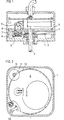
- the angle measuring device shown in Figure 1 has a housing 1 which is fastened in the housing of an industrial robot, not shown.
- a shaft 2 which is rotatably mounted in the housing 1, projects into the housing 1 and carries there a disk 3 with an incremental division 4 in the form of a grid.
- the incremental division 4 is scanned electrically.
- a second disk 5 is provided, which is also rotatably mounted on the shaft 2.
- the second disc 5 In the normal operating state, the second disc 5 is stationary, so that the lighting device 6 with condenser 7, scanning plate 8 and photo elements 9 fastened in it is also stationary and when the indexing disc 3 rotates, its movement by modulation of the one passing through the grating 4 and the scanning plate 8 Luminous flux is detected in a known manner by the photo elements 9 and is counted as an measured value in an electronic counter Z.
- the housing 1 is fixed in the housing A of the industrial robot, and the shaft 2 is fixedly connected to a handling module, for example a gripper B (see FIG. 3).
- a handling module for example a gripper B (see FIG. 3).
- the rotations that the gripper B executes are detected by the measuring device and passed on to an evaluation device Z for measuring or control purposes.
- reference marks are provided along the graduation track (as described, for example, in DE-OS-1 673 887 mentioned at the beginning or also in DE-PS-2 952 106).
- the gripper B is rotated until one of the reference marks is reached. This position is declared "zero", or another numerical value that has been previously defined or determined by a program is set in the counter Z there. During the subsequent work movements of the robot, this value selected at the beginning is the reference basis.
- the adjustment to the reference base can be done in the manner described in DE-OS-1 673 887 on page 14 above.
- the measured value pending when the fault occurs is lost, including the reference to the starting position.
- the tool of the gripper B since in the event of a malfunction the tool of the gripper B is currently engaged, it is not possible, as at the beginning of the working cycle, to rotate the gripper B until the original reference mark is detected by the scanning device.
- the measuring device is equipped with a drive motor 10.
- the drive motor 10 has a pinion 11 which meshes in an external toothing 12 of the disk 5 (FIG. 2).
- the drive motor 10 is activated and rotates the disk 5 via the gear 11/12 until the scanning device consisting of the lighting device 6, condenser 7, scanning plate 8 and photo elements 9 passes over a reference mark.
- the counter is reset to "zero" or the other selected value by the reference marks, the drive motor 10 is switched off and the disk 5 returns to the position in the event of a fault.
- the increments of the grating division 4 are counted and the distance of the current position from the reference position is known again.
- the invention can be carried out in a particularly advantageous manner with a device according to FIGS. 3 to 5.
- a shaft 32 is supported, among other things, which carries a disk 33 with an incremental grating 34 (see also FIG. 5).
- the shaft 32 carries a further disk 35 on which a scanning plate 38 is attached.
- the disk 35 is rotatably mounted on the shaft 32 and has a structure on its upper side facing away from the partial disk 33, which is provided with a switching arm 351 and a fork 352.
- An eccentric 311 engages between the arms of the fork 352 and sits on the axis of a drive motor 310.
- the drive motor 310 is fixed in place in the housing 31 in a holder 30.
- the illumination device 36, the condenser 37 and the photo elements 39 for scanning the grating division 34 and the reference marks R, to R n are likewise arranged in a stationary manner in the housing 31.
- the disc 35 In the idle state, the disc 35 is adjusted in position by a stop 353. The disc 35 has this position in the normal operating state.
- the normal function runs as described for Figures 1 and 2.
- a field of a certain size is illuminated by the lighting device 36 and the condenser 37.
- the arrangement of the reference marks R to R n and the photo elements 39 are matched to the size of this light field.
- a series of reference marks R i to R n are provided along the grating 34, which are arranged on a concentric track.
- the individual reference marks R, to R n are provided with code marks C, to C n and thus numbered, so to speak.
- the code mark Ci characterizes the distance of the associated reference mark Ri from a specific zero point of the grating division 34.
- the distribution of the reference marks R, to R n is dimensioned such that the reference mark R, exactly 100 grating graduation marks from the zero point of the division is removed, the reference mark R 2 exactly 200 grating marks etc. With a grating constant of 40 .mu.m this means that a reference mark Ri is arranged every 4 mm.
- the size of the illuminated field is designed such that one of the reference marks R 1 to R, and the associated code marks C 1 to C, lies within this illuminated field at each position of the index plate 33.
- the second of the rotatable disks 35 with the scanning plate 38 only has to be pivoted by a maximum of 4 mm in order to reliably scan one of the reference marks R 1 to R n and the code mark located at the reference marks.
- the counter Z is then set to the numerical value which is determined by the code mark Ci of the scanned reference mark Ri. From this value, the grid lines of the division 34 are counted during the pivoting back movement of the disk 35 until the disk 35 has reached its starting position - fixed by the stop 353.
- the instantaneous position in relation to the reference position has now been determined again and is represented as the measured value which results from the reference mark position (determined - by the code mark) and the count value of the grating lines of the graduation 34 superimposed on this, which also occurs when the scanning plate 38 moves back the disc 35 was determined.
- the vibration-sensitive lighting device 36 does not have to be moved during this process and will therefore have a longer service life. Adjustment problems do not occur because of the unchangeable position of the lighting device 36.
- the pivoting movement of the disk 35 is carried out by a drive motor 310, on the axis of which an eccentric 311 is seated.
- the eccentric 311 lies between the arms of a fork 352, which forms a structure on the top of the disk 35.
- a spring 354 supports the pivoting back and secures the exact contact at the stop 353.
- a switch 355 is actuated by a switching arm 351 on the upper structure of the disk 35, which stops the drive motor 310.
- the drive motor 310 has a small time constant, so that one revolution of the eccentric 311, that is to say also a complete pivoting movement of the disk 35, is completed within a tenth of a second.
- the measuring device described above works so quickly that not only can the reference position be reproduced safely in the event of malfunctions, but in the case of such a "calibration step" of only a tenth of a second, robots can easily pass such "calibration steps" from the program between the individual work processes provide controlled, which significantly increases the operational safety of such systems.
- the angle measuring device shown in longitudinal section in FIG. 6 has a housing G which is attached to a measuring object 0, for example to a housing of an industrial robot (not shown).
- a first shaft W is rotatably supported by means of the bearing L and carries a graduated disk T with an incremental graduation and with reference marks absolutely assigned to the incremental graduation.
- the incremental graduation and the reference marks of the graduated disk T are light-electrically scanned by a scanning unit AE fastened in the housing G, which has a lighting unit BE with a condenser CD, a scanning plate AP and photo elements P on a board PL fastened in the housing G.
- the rotation of the graduated disk T is detected by the modulation of the light flux passing through the divisions of the graduated disk T and the scanning plate AP in a known manner by the photoelements P, whose periodic scanning signals are used by a counter to determine a measured value for the relative position of the graduated disk T with respect to the scanning unit AE be forwarded.
- the first shaft W is connected via a driver clutch K, to a second shaft W 2 , which is likewise mounted in the interior of the housing G by means of bearing L 2 and from the housing G for attachment to the other rotatable object O to be measured 2 , for example on a gripper of the industrial robot, protrudes.
- the driver clutch K consists of a connecting hub F 1 , which is fixed on the shaft W, and a connecting hub F 2 , which is fixed on the shaft W 2 , and an annular disc RS.
- a connecting hub F 1 which is fixed on the shaft W
- a connecting hub F 2 which is fixed on the shaft W 2
- an annular disc RS At the periphery of the two connection hubs F 1 , F 2 , three stops S t , S 2, each offset by 120 ° to one another, protrude in the radial direction.
- the ring disk RS is arranged, which has on its periphery three bolts BZ offset by 120 ° to one another, which protrude in the axial direction from bores on both sides of the ring disk RS and with the stops S 1 , S 2 connecting hub F 1, F 2 are in contact with a rotation of the waves W l, W. 2
- the annular disc RS has no own bearing and is self-centering due to the symmetrical arrangement of the bolts BZ when the shafts W 1 , W 2 rotate and exerts on the bearings L 1 , L 2 of the shafts W 1 . W 2 no lateral force.
- the driver clutch K takes one predetermined direction of rotation of the rotatable object O 2 and thus the shaft W 2 via the bolts BZ in contact with each other of the ring disk RS and stops S 1 , S 2 of the connection hubs F 1 , F 2, the shaft W 1 with the indexing disk T with. If the predetermined direction of rotation of the shaft W 2 is reversed, the shaft W 1 is no longer taken along, since the bolts BZ of the ring disk RS and the stops S 2 of the connecting hub F 2 become out of contact.
- the clutch plate K 1 facing away from the shaft end of the shaft is W 1 via a slip clutch K 2 with a Coupled in the housing G drive motor M, which drives the shaft W 1 against the predetermined direction of rotation of the shaft W 2 .
- the two waves W 1, W 2 are thus fixed to each other so that the relative position of the two can be determined exactly by the angle measuring objects to be measured 2 0 0. 1
- the object O 2 to be measured is rotated before the start of a new measurement with the drive motor M acting until a reference mark is scanned.
- the counter is set to the value "zero" or to another numerical value that has been defined beforehand or determined by a program.
- the drive motor M is reversed when the shaft W 2 is stationary; the drive motor M rotates the shaft W 1 with the indexing disk T via the slip clutch K 2 in the reverse direction of rotation until the scanning unit AE scans the original reference mark again, so that the counter is reset to the original value.
- the drive motor M is then reversed in the original direction of rotation and the shaft W 1 with the indexing disk T is turned back until the stops S 1 of the connection hub F 1 come into contact with the bolts BZ of the ring disk RS, so that the shaft W 1 and the indexing disk T once again have the current position when the fault occurred.
- the driving clutch K 1 has bolts BZ and stops S 1 , S 2 which are offset by 120 ° relative to each other, and thus a relative movement of the shaft W 1 with respect to the shaft W 2 is only possible within an angle ⁇ 240 ° when reproducing the reference position
- At least two reference marks are required on the graduated disk T to reproduce a lost reference position, which require coding in the form of code marks to differentiate between them, as described, for example, in DE-PS-2 952 106.
- a driver clutch K 1 'according to FIG. 7 which has a relative rotation of the shaft W 1 with respect to the shaft W 2 enables an angle of 360 °.
- the connecting hub F 2 'with the three stops S 2 ' offset from one another by 120 ° for connecting the shaft W 2 is identical to the connecting hub F 2 in FIG. 6 (FIG. 7b).
- connection hub F 1 'for connecting the shaft W 1 has, according to Figure 7b, 7c three radially and axially offset concentric stages U 1', U 2 ', U 3', wherein from each stage U 1 ', U 2', U 3 'a stop S 1 ' protrudes in the radial direction; the three stops S 1 'on the three stages U 1 ', U 2 ', U 3 ' are offset by 120 ° to each other.
- the annular disk RS' On the side facing the connection hub F 1 ', the annular disk RS' has three radially and axially offset concentric stages U 1 "U 2 ", U 3 ", with a bolt BZ from each stage U 1 ", U 2 “, U3” 1 'protrudes in the axial direction; the three bolts BZ 1 'on the steps U 1 ", U 2 “, U 3 “are offset from one another by 120 ° and come into contact with the respectively associated stops S 1 ' of the connection hub F 1 '.
- the stops S 2 'of the connecting hub F 2 ' and the associated bolts BZ 2 'of the ring disk RS' can be arranged on radially and axially offset concentric steps.
- the clutch K 1 can also be designed as a simple driver.
- the slip clutch K 2 can be designed as an eddy current brake, as a hydraulic clutch or as a magnetic driver.
- the Partial disk T can also be connected directly to the drive unit M.
Landscapes
- Physics & Mathematics (AREA)
- General Physics & Mathematics (AREA)
- Manipulator (AREA)
- Length Measuring Devices With Unspecified Measuring Means (AREA)
- Transmission And Conversion Of Sensor Element Output (AREA)
Claims (15)
Priority Applications (1)
| Application Number | Priority Date | Filing Date | Title |
|---|---|---|---|
| AT84101254T ATE48032T1 (de) | 1983-03-26 | 1984-02-08 | Vorrichtung zum reproduzieren einer bezugsposition. |
Applications Claiming Priority (4)
| Application Number | Priority Date | Filing Date | Title |
|---|---|---|---|
| DE3311203 | 1983-03-26 | ||
| DE19833311203 DE3311203A1 (de) | 1983-03-26 | 1983-03-26 | Verfahren zum reproduzieren einer bezugsposition |
| DE3340866 | 1983-11-11 | ||
| DE19833340866 DE3340866A1 (de) | 1983-03-26 | 1983-11-11 | Wegmesseinrichtung |
Publications (3)
| Publication Number | Publication Date |
|---|---|
| EP0126843A2 EP0126843A2 (fr) | 1984-12-05 |
| EP0126843A3 EP0126843A3 (en) | 1987-08-05 |
| EP0126843B1 true EP0126843B1 (fr) | 1989-11-15 |
Family
ID=25809480
Family Applications (1)
| Application Number | Title | Priority Date | Filing Date |
|---|---|---|---|
| EP84101254A Expired EP0126843B1 (fr) | 1983-03-26 | 1984-02-08 | Dispositif de reétablissement d'une position de référence |
Country Status (3)
| Country | Link |
|---|---|
| US (1) | US4530155A (fr) |
| EP (1) | EP0126843B1 (fr) |
| DE (2) | DE3340866A1 (fr) |
Families Citing this family (29)
| Publication number | Priority date | Publication date | Assignee | Title |
|---|---|---|---|---|
| DE3527546C1 (de) * | 1985-08-01 | 1986-10-02 | Dr. Johannes Heidenhain Gmbh, 8225 Traunreut | Vorrichtung zum Verbinden einer Positionsmesseinrichtung mit zwei relativ zueinander beweglichen Objekten |
| DD284772A5 (de) * | 1989-06-02 | 1990-11-21 | Veb Carl Zeiss Jena,Dd | Verfahren und anordnung zur ueberwachung eines winkel- oder laengenmesssystems an einer maschine |
| FR2668258B1 (fr) * | 1990-10-19 | 1994-05-13 | Cartier Systemes G | Capteur d'angle de rotation pour detecter le sens de rotation et/ou le nombre de tours effectues, et dispositif de direction assitee de vehicule comportant un tel capteur. |
| AT397717B (de) * | 1990-12-10 | 1994-06-27 | Rieder & Schwaiger Sentop | Drehgeber |
| US5435067A (en) * | 1991-06-06 | 1995-07-25 | Toshiba Kikai Kabushiki Kaisha | Method and apparatus for indexing attachment |
| DE4216234A1 (de) * | 1992-05-16 | 1993-11-18 | Karl Kessler | Meßmaschine |
| US5642297A (en) * | 1994-12-12 | 1997-06-24 | Gurley Precision Instruments, Inc. | Apparatus and method for measuring the kinematic accuracy in machines and mechanisms using absolute encoders |
| US6293022B1 (en) * | 1997-04-25 | 2001-09-25 | Kabushiki Kaisha Toyoda Jidoshokki Seisakusho | Mounting structure for wheel angle detector and rotation amount detector for vehicle wheel |
| WO1999042790A1 (fr) | 1998-02-21 | 1999-08-26 | Dr. Johannes Heidenhain Gmbh | Procede permettant de faire fonctionner un systeme de mesure de position et systeme de mesure de position approprie |
| DE19820014A1 (de) | 1998-05-06 | 1999-11-11 | Heidenhain Gmbh Dr Johannes | Multiturn-Codedrehgeber |
| DE19831744A1 (de) * | 1998-07-15 | 2000-01-20 | Zeiss Carl Fa | Stellvorrichtung |
| US6417638B1 (en) * | 1998-07-17 | 2002-07-09 | Sensable Technologies, Inc. | Force reflecting haptic interface |
| DE59912617D1 (de) | 1998-08-01 | 2006-02-16 | Heidenhain Gmbh Dr Johannes | Rotatorische Positionsmesseinrichtung |
| DE19836003A1 (de) | 1998-08-08 | 2000-02-10 | Heidenhain Gmbh Dr Johannes | Verfahren zur Montage einer Positionsmeßeinrichtung und Positioniermittel zur Montage |
| DE19839028C1 (de) * | 1998-08-27 | 2000-02-10 | Asm Automation Sensorik Messte | Meßseil-Wegsensor |
| DE19904471B4 (de) | 1999-02-04 | 2011-03-31 | Dr. Johannes Heidenhain Gmbh | Drehgeber |
| DE19907326B4 (de) | 1999-02-20 | 2013-04-04 | Dr. Johannes Heidenhain Gmbh | Winkelmeßsystem |
| JP4240774B2 (ja) | 2000-07-17 | 2009-03-18 | 株式会社東海理化電機製作所 | 回転角度検出装置及び回転角度検出方法 |
| JP2002039798A (ja) * | 2000-07-19 | 2002-02-06 | Tokai Rika Co Ltd | 回転角度検出装置及び回転角度検出方法 |
| DE20015505U1 (de) * | 2000-09-07 | 2001-07-12 | Noltronic Grecon Greten GmbH & Co. KG, 58507 Lüdenscheid | Messeinrichtung zur kontinuierlichen Erfassung der Dicke langgestreckter Werkstücke |
| DE10060574A1 (de) * | 2000-12-06 | 2002-06-13 | Heidenhain Gmbh Dr Johannes | Multiturn-Codedrehgeber |
| DE10117193B4 (de) * | 2001-04-05 | 2013-04-04 | Anton Rodi | Messsystem zur Absolutwerterfassung von Winkeln oder Wegen |
| US6922907B2 (en) | 2001-04-05 | 2005-08-02 | Anton Rodi | Measuring system for recording absolute angular or position values |
| KR20040097124A (ko) * | 2002-02-08 | 2004-11-17 | 로베르트 보쉬 게엠베하 | 광학 토크 및 각 센서 |
| US7411576B2 (en) | 2003-10-30 | 2008-08-12 | Sensable Technologies, Inc. | Force reflecting haptic interface |
| JP3826207B2 (ja) * | 2004-08-31 | 2006-09-27 | 独立行政法人産業技術総合研究所 | 自己校正機能付き角度検出器 |
| CN102230783B (zh) * | 2011-05-04 | 2012-09-26 | 南京航空航天大学 | 一种用于工业机器人的空间立体网格精度补偿方法 |
| US20140260522A1 (en) * | 2013-03-14 | 2014-09-18 | The Raymond Corporation | Home position indicator, encoder position measurement system including a home position indicator, and a method of detecting a home position |
| CN106001927B (zh) * | 2016-07-05 | 2018-03-23 | 温州大学激光与光电智能制造研究院 | 一种测量加工一体化的激光平整化抛光方法 |
Family Cites Families (12)
| Publication number | Priority date | Publication date | Assignee | Title |
|---|---|---|---|---|
| DE1673887A1 (de) * | 1968-01-16 | 1972-01-20 | Heidenhain Gmbh Dr Johannes | Anordnung zur Bestimmung der Lage zweier relativ zueinander beweglicher Teile |
| NL6907384A (fr) * | 1969-05-14 | 1970-11-17 | ||
| DE1933254C3 (de) * | 1969-07-01 | 1979-08-16 | Dr. Johannes Heidenhain Gmbh, 8225 Traunreut | Inkrementales Längen- oder Winkelmeßsystem |
| US3637312A (en) * | 1969-10-31 | 1972-01-25 | Nasa | Roll alignment detector |
| GB1284641A (en) * | 1970-01-08 | 1972-08-09 | Ferranti Ltd | Improvements relating to measuring apparatus |
| DE7101141U (de) * | 1971-01-14 | 1972-01-13 | Haeberle G | Messeinrichtung fuer werkzeugmaschinen |
| US3997782A (en) * | 1974-09-06 | 1976-12-14 | Dynapar Corporation | Rotary pulse transducer having stator sealing means |
| FR2406804A1 (fr) * | 1977-10-20 | 1979-05-18 | Sercel Rech Const Elect | Codeur angulaire a angle d'entree variable |
| US4318225A (en) * | 1979-12-04 | 1982-03-09 | Mchenry Systems, Inc. | Angle measuring apparatus |
| DE2952106C2 (de) * | 1979-12-22 | 1982-11-04 | Dr. Johannes Heidenhain Gmbh, 8225 Traunreut | Lichtelektrische inkrementale Längen- oder Winkelmeßeinrichtung |
| IT1129862B (it) * | 1980-11-17 | 1986-06-11 | Olivetti & Co Spa | Trasduttore ottico |
| DE3311203A1 (de) * | 1983-03-26 | 1984-10-04 | Dr. Johannes Heidenhain Gmbh, 8225 Traunreut | Verfahren zum reproduzieren einer bezugsposition |
-
1983
- 1983-11-11 DE DE19833340866 patent/DE3340866A1/de active Granted
-
1984
- 1984-02-08 EP EP84101254A patent/EP0126843B1/fr not_active Expired
- 1984-02-08 DE DE8484101254T patent/DE3480489D1/de not_active Expired
- 1984-03-20 US US06/591,407 patent/US4530155A/en not_active Expired - Fee Related
Also Published As
| Publication number | Publication date |
|---|---|
| EP0126843A2 (fr) | 1984-12-05 |
| US4530155A (en) | 1985-07-23 |
| DE3340866C2 (fr) | 1988-02-25 |
| EP0126843A3 (en) | 1987-08-05 |
| DE3480489D1 (en) | 1989-12-21 |
| DE3340866A1 (de) | 1985-05-23 |
Similar Documents
| Publication | Publication Date | Title |
|---|---|---|
| EP0126843B1 (fr) | Dispositif de reétablissement d'une position de référence | |
| EP0211195B1 (fr) | Dispositif d'accouplement | |
| DE2909227C2 (fr) | ||
| EP0252164B1 (fr) | Méthode et dispositif pour déterminer la position radiale d'un profil neuf obtenu par fraisage | |
| EP0126211A2 (fr) | Dispositif incrémental de mesure de longueurs ou d'angles | |
| DE3020532C2 (fr) | ||
| EP0165392B1 (fr) | Appareil de mesure de la position | |
| DE2808337C3 (de) | Automatische Rohrschweinmaschine | |
| EP3501730B1 (fr) | Machine à fraiser dentaire ainsi que procédé | |
| EP0157239B1 (fr) | Dispositif de mesure de position | |
| CH666123A5 (de) | Selbsttaetig arbeitendes zahnradpruefgeraet. | |
| DE19621015A1 (de) | Verfahren und Vorrichtung zur Positionierung von bewegten Maschinenteilen | |
| DE3415091C1 (de) | Positionsmeßeinrichtung | |
| DE3311203C2 (fr) | ||
| DE2414956C3 (de) | Vorrichtung zum Unterscheiden der An- und Abwesenheit von Gegenständen | |
| DE2632938C3 (de) | Kraftbetätigtes Spannfutter für Senkrechtdrehmaschinen | |
| DE2054643A1 (de) | Vorrichtung zur Bestimmung von Abmessungen | |
| DE3512359A1 (de) | Antriebs- und positioniervorrichtung | |
| DE3509838C2 (fr) | ||
| DE3327549C2 (de) | Selbsttätig arbeitendes Zahnradprüfgerät | |
| DE3420187C1 (de) | Positionsmeßeinrichtung | |
| DE3539471C1 (de) | Vorrichtung zum Verschwenken einer Werkzeugaufnahmevorrichtung, insbesondere eines Winkelfräskopfes, am freien (unteren) Ende eines Frässpindelstockes | |
| DE8332471U1 (de) | Wegmeßeinrichtung | |
| EP3517884A1 (fr) | Dispositif et procédé de support de pièces de forme complexe | |
| DE8416558U1 (de) | Positionsmeßeinrichtung |
Legal Events
| Date | Code | Title | Description |
|---|---|---|---|
| PUAI | Public reference made under article 153(3) epc to a published international application that has entered the european phase |
Free format text: ORIGINAL CODE: 0009012 |
|
| 17P | Request for examination filed |
Effective date: 19840215 |
|
| AK | Designated contracting states |
Designated state(s): AT CH DE FR GB IT LI NL SE |
|
| PUAL | Search report despatched |
Free format text: ORIGINAL CODE: 0009013 |
|
| AK | Designated contracting states |
Kind code of ref document: A3 Designated state(s): AT CH DE FR GB IT LI NL SE |
|
| 17Q | First examination report despatched |
Effective date: 19880927 |
|
| ITF | It: translation for a ep patent filed | ||
| GRAA | (expected) grant |
Free format text: ORIGINAL CODE: 0009210 |
|
| AK | Designated contracting states |
Kind code of ref document: B1 Designated state(s): AT CH DE FR GB IT LI NL SE |
|
| REF | Corresponds to: |
Ref document number: 48032 Country of ref document: AT Date of ref document: 19891215 Kind code of ref document: T |
|
| ET | Fr: translation filed | ||
| GBT | Gb: translation of ep patent filed (gb section 77(6)(a)/1977) | ||
| REF | Corresponds to: |
Ref document number: 3480489 Country of ref document: DE Date of ref document: 19891221 |
|
| RAP4 | Party data changed (patent owner data changed or rights of a patent transferred) |
Owner name: DR. JOHANNES HEIDENHAIN GMBH |
|
| PLBE | No opposition filed within time limit |
Free format text: ORIGINAL CODE: 0009261 |
|
| STAA | Information on the status of an ep patent application or granted ep patent |
Free format text: STATUS: NO OPPOSITION FILED WITHIN TIME LIMIT |
|
| 26N | No opposition filed | ||
| PGFP | Annual fee paid to national office [announced via postgrant information from national office to epo] |
Ref country code: CH Payment date: 19910118 Year of fee payment: 8 |
|
| PGFP | Annual fee paid to national office [announced via postgrant information from national office to epo] |
Ref country code: AT Payment date: 19910124 Year of fee payment: 8 |
|
| PGFP | Annual fee paid to national office [announced via postgrant information from national office to epo] |
Ref country code: SE Payment date: 19910128 Year of fee payment: 8 |
|
| PGFP | Annual fee paid to national office [announced via postgrant information from national office to epo] |
Ref country code: NL Payment date: 19910228 Year of fee payment: 8 |
|
| PG25 | Lapsed in a contracting state [announced via postgrant information from national office to epo] |
Ref country code: AT Effective date: 19920208 |
|
| PG25 | Lapsed in a contracting state [announced via postgrant information from national office to epo] |
Ref country code: SE Effective date: 19920209 |
|
| PG25 | Lapsed in a contracting state [announced via postgrant information from national office to epo] |
Ref country code: LI Effective date: 19920229 Ref country code: CH Effective date: 19920229 |
|
| PG25 | Lapsed in a contracting state [announced via postgrant information from national office to epo] |
Ref country code: NL Effective date: 19920901 |
|
| NLV4 | Nl: lapsed or anulled due to non-payment of the annual fee | ||
| REG | Reference to a national code |
Ref country code: CH Ref legal event code: PL |
|
| ITTA | It: last paid annual fee | ||
| EUG | Se: european patent has lapsed |
Ref document number: 84101254.5 Effective date: 19920904 |
|
| PGFP | Annual fee paid to national office [announced via postgrant information from national office to epo] |
Ref country code: GB Payment date: 19980112 Year of fee payment: 15 |
|
| PGFP | Annual fee paid to national office [announced via postgrant information from national office to epo] |
Ref country code: FR Payment date: 19980116 Year of fee payment: 15 |
|
| PGFP | Annual fee paid to national office [announced via postgrant information from national office to epo] |
Ref country code: DE Payment date: 19990122 Year of fee payment: 16 |
|
| PG25 | Lapsed in a contracting state [announced via postgrant information from national office to epo] |
Ref country code: GB Free format text: LAPSE BECAUSE OF NON-PAYMENT OF DUE FEES Effective date: 19990208 |
|
| GBPC | Gb: european patent ceased through non-payment of renewal fee |
Effective date: 19990208 |
|
| PG25 | Lapsed in a contracting state [announced via postgrant information from national office to epo] |
Ref country code: FR Free format text: LAPSE BECAUSE OF NON-PAYMENT OF DUE FEES Effective date: 19991029 |
|
| REG | Reference to a national code |
Ref country code: FR Ref legal event code: ST |
|
| PG25 | Lapsed in a contracting state [announced via postgrant information from national office to epo] |
Ref country code: DE Free format text: LAPSE BECAUSE OF NON-PAYMENT OF DUE FEES Effective date: 20001201 |