EP0126860A2 - Vorrichtung zur digitalen Winkelmessung - Google Patents
Vorrichtung zur digitalen Winkelmessung Download PDFInfo
- Publication number
- EP0126860A2 EP0126860A2 EP84102188A EP84102188A EP0126860A2 EP 0126860 A2 EP0126860 A2 EP 0126860A2 EP 84102188 A EP84102188 A EP 84102188A EP 84102188 A EP84102188 A EP 84102188A EP 0126860 A2 EP0126860 A2 EP 0126860A2
- Authority
- EP
- European Patent Office
- Prior art keywords
- circle
- division
- marks
- stator
- rotor
- Prior art date
- Legal status (The legal status is an assumption and is not a legal conclusion. Google has not performed a legal analysis and makes no representation as to the accuracy of the status listed.)
- Granted
Links
- 238000005259 measurement Methods 0.000 title claims abstract description 15
- 125000004122 cyclic group Chemical group 0.000 claims description 2
- 230000000630 rising effect Effects 0.000 claims 1
- 238000000034 method Methods 0.000 abstract 1
- 230000000737 periodic effect Effects 0.000 abstract 1
- 238000011156 evaluation Methods 0.000 description 1
Classifications
-
- G—PHYSICS
- G01—MEASURING; TESTING
- G01D—MEASURING NOT SPECIALLY ADAPTED FOR A SPECIFIC VARIABLE; ARRANGEMENTS FOR MEASURING TWO OR MORE VARIABLES NOT COVERED IN A SINGLE OTHER SUBCLASS; TARIFF METERING APPARATUS; MEASURING OR TESTING NOT OTHERWISE PROVIDED FOR
- G01D5/00—Mechanical means for transferring the output of a sensing member; Means for converting the output of a sensing member to another variable where the form or nature of the sensing member does not constrain the means for converting; Transducers not specially adapted for a specific variable
- G01D5/12—Mechanical means for transferring the output of a sensing member; Means for converting the output of a sensing member to another variable where the form or nature of the sensing member does not constrain the means for converting; Transducers not specially adapted for a specific variable using electric or magnetic means
- G01D5/244—Mechanical means for transferring the output of a sensing member; Means for converting the output of a sensing member to another variable where the form or nature of the sensing member does not constrain the means for converting; Transducers not specially adapted for a specific variable using electric or magnetic means influencing characteristics of pulses or pulse trains; generating pulses or pulse trains
- G01D5/247—Mechanical means for transferring the output of a sensing member; Means for converting the output of a sensing member to another variable where the form or nature of the sensing member does not constrain the means for converting; Transducers not specially adapted for a specific variable using electric or magnetic means influencing characteristics of pulses or pulse trains; generating pulses or pulse trains using time shifts of pulses
Definitions
- the present invention relates to a device according to the preamble of patent claim 1.
- the zero mark must appear once on the stator-fixed and rotor-fixed encoder. This requires an observation period, which in the worst case is a full revolution of the circle. In certain applications this is annoying.
- a theodolite-like instrument for example two angles around different axes (azimuth and elevation) must be measured alternately with the same evaluation electronics. When setting out, this should be done in quick succession (about 2 to 4 complete measurements per second).
- this arises to receive rough information from just a fraction of a full revolution.
- the object of the invention is to fulfill this wish and to substantially reduce the additional effort mentioned above.
- These difficulties mentioned are avoided by the fact that the mark is not realized by omitting a stroke, but only by disturbing the stroke width, and in such a way that the one edge of all division marks still represents an equidistant division undisturbed over the entire circle is used for phase measurement, while the brand disturbance consists only in a shift of the other edge. It has proven to be particularly advantageous to select approximately 2/3 or 1/3 of the division interval as the line width of the undisturbed or disturbed line.
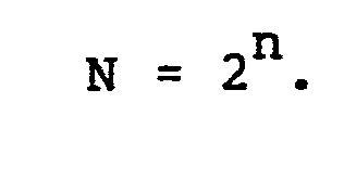
- the rough information is obtained by applying equidistant marks, where N is advantageously a power of two: If n) is 1, the marks must be identified (coded). In a first embodiment of the invention, this is achieved by using groups of n + 1 consecutive tick marks as marks, the first stroke always being disturbed, while the states of the following n represent a binary code that numbers the mark.
- each mark consists of two successive lines, the first of which is always disturbed, while the state of the second represents a code bit.
- the code bits of all brands form a cyclic code, which is such that any n consecutive code bits form a word unique on the circle.
Landscapes
- Physics & Mathematics (AREA)
- General Physics & Mathematics (AREA)
- Transmission And Conversion Of Sensor Element Output (AREA)
- Measurement Of Length, Angles, Or The Like Using Electric Or Magnetic Means (AREA)
Abstract
Description
- Die vorliegende Erfindung betrifft eine Vorrichtung gemäss dem Oberbegriff des Patentanspruches 1.
- Die Messung einer Phasendifferenz mit dieser Vorrichtung ergibt eine Interpolation des Teilungsintervalles (Feinmessung), während die im zu messenden Winkel enthaltene Anzahl ganze Teilungsintervalle noch unbekannt ist.
- Bekannt sind Ausführungen, bei denen der Kreis neben der Teilung noch eine einzelne Marke (Nullmarke) aufweist, welche durch je einen zusätzlichen statorfesten und rotorfesten Geber abgetastet wird. Die noch unbekannte Anzahl ganzer Intervalle (Grobmessung) erhält man, indem zwischen aufeinanderfolgenden Durchgängen der Nullmarke am statorfesten und rotorfesten Markengeber die Signalperioden eines Teilungsgebers gezählt werden.
- Ferner sind Lösungen bekannt, bei denen die Nullmarke in die Teilung integriert und durch Auslassen eines Teilstriches realisiert ist. Dadurch spart man die zusätzlichen Markengeber ein. Dagegen muss zusätzlicher Aufwand getrieben werden,um für dBFeinmessung die fehlende Signalperiode zu rekonstruieren.
- Für die Grobmessung muss die Nullmarke am statorfesten und rotorfesten Geber je einmal erscheinen. Das erfordert eine Beobachtungsdauer, die im ungünstigsten Fall eine volle Umdrehung des Kreises beträgt. In gewissen Anwendungsfällen stört dies. Bei einem theodolitartigen Instrument z.B. müssen mit derselben Auswerteelektronik abwechselnd zwei Winkel um verschiedene Achsen (Azimut und Elevation) gemessen werden. Bei Absteckarbeiten sollte dies in schneller Folge geschehen (etwa 2 bis 4 komplette Messungen pro Sek.). Hier entsteht der Wunsch, eine Grobinformation bereits aus einem Bruchteil einer vollen Kreisumdrehung zu erhalten.
- Aufgabe der Erfindung ist es, diesen Wunsch zu erfüllen sowie den oben erwähnten zusätzlichen Aufwand wesentlich zu reduzieren. Diese genannten Schwierigkeiten werden dadurch umgangen, dass die Marke nicht durch Auslassen eines Striches, sondern nur durch eine Störung der Strichbreite realisiert ist, und zwar so, dass die eine Kante aller Teilstriche nach wie vor eine über den ganzen Kreis ungestörte aequidistante Teilung darstellt, die zur Phasenmessung dient, während die Markenstörung nur in einer Verschiebung der anderen Kante besteht. Als besonders vorteilhaft hat es sich erwiesen, als Strichbreite des ungestörten oder gestörten Striches etwa 2/3 bzw. 1/3 des Teilungsintervalles zu wählen.
- Die Gewinnung der Grobinformation wird erfindungsgemäss durch Anbringen von N aequidistanten Marken gelöst, wobei N mit Vorteil eine Zweierpotenz ist:
- In einer zweiten Ausführungsform der Erfindung besteht jede Marke aus zwei aufeinanderfolgenden Strichen, von denen der erste immer gestört ist, während der Zustand des zweiten ein Codebit darstellt. Die Codebits aller Marken bilden einen zyklischen Code, der so beschaffen ist, dass beliebige n aufeinanderfolgende Codebits ein auf dem Kreis einmaliges Wort bilden.
- Solche Codes für verschiedene n sind bekannt. Sie können z.B. mit Schiebezählern (geeignete rückgekoppelte Schieberegister) erzeugt werden. So erzeugt man mit einem 6-Bit-Schieberegister und der Rückkoppelungsregel


- Darin kommt jedes mögliche 6-Bit-Wort genau einmal vor, mit Ausnahme von 000000. Man darf aber bei der Gruppe 00000 eine sechste 0 hinzufügen. Es stört bei der vorliegenden Anwendung nicht, dass dann der Schiebezähler'nach 000000 nicht mehr weiterlaufen würde.
Claims (5)
Applications Claiming Priority (2)
| Application Number | Priority Date | Filing Date | Title |
|---|---|---|---|
| CH1167/83A CH659889A5 (de) | 1983-03-03 | 1983-03-03 | Vorrichtung zur digitalen winkelmessung. |
| CH1167/83 | 1983-03-03 |
Publications (3)
| Publication Number | Publication Date |
|---|---|
| EP0126860A2 true EP0126860A2 (de) | 1984-12-05 |
| EP0126860A3 EP0126860A3 (en) | 1987-06-03 |
| EP0126860B1 EP0126860B1 (de) | 1990-01-31 |
Family
ID=4204040
Family Applications (1)
| Application Number | Title | Priority Date | Filing Date |
|---|---|---|---|
| EP84102188A Expired - Lifetime EP0126860B1 (de) | 1983-03-03 | 1984-03-01 | Vorrichtung zur digitalen Winkelmessung |
Country Status (5)
| Country | Link |
|---|---|
| US (1) | US4623790A (de) |
| EP (1) | EP0126860B1 (de) |
| CA (1) | CA1225151A (de) |
| CH (1) | CH659889A5 (de) |
| DE (1) | DE3481217D1 (de) |
Families Citing this family (6)
| Publication number | Priority date | Publication date | Assignee | Title |
|---|---|---|---|---|
| DE3809569A1 (de) * | 1988-03-22 | 1989-10-05 | Frankl & Kirchner | Positionsgeber |
| JPH0634872A (ja) * | 1992-07-14 | 1994-02-10 | Sony Corp | サンプリング系位置検出装置 |
| JP3168451B2 (ja) * | 1995-09-24 | 2001-05-21 | 株式会社トプコン | ロータリーエンコーダ |
| KR101034691B1 (ko) * | 2004-11-23 | 2011-06-13 | 두산인프라코어 주식회사 | 마그네틱 픽업 센서를 사용하는 디지털 가버너의속도검출장치 |
| TW200636192A (en) * | 2005-03-22 | 2006-10-16 | Miura Kogyo Kk | Damper position adjusting device and combustion apparatus having such damper adjusting device |
| US7430087B2 (en) * | 2006-09-05 | 2008-09-30 | International Business Machines Corporation | Method and device for servo frame velocity calculations of a storage media |
Family Cites Families (5)
| Publication number | Priority date | Publication date | Assignee | Title |
|---|---|---|---|---|
| DE1208087B (de) * | 1964-04-22 | 1965-12-30 | Wenczler & Heidenhain | Einrichtung zum Messen von Laengen mittels Impulszaehlung |
| NL6907384A (de) * | 1969-05-14 | 1970-11-17 | ||
| FR2354592A1 (fr) | 1976-06-09 | 1978-01-06 | Secap | Dispositif pour le reperage de la position d'un organe mobile, notamment d'un organe de mise en valeur dans une machine d'affranchissement |
| FR2410826A1 (fr) | 1977-12-02 | 1979-06-29 | Renault | Procede de reperage de la position angulaire d'une piece animee d'un mouvement de rotation et appareil en faisant application |
| DE3018496A1 (de) * | 1980-05-14 | 1981-11-19 | Walter Dipl.-Ing. Dr.-Ing. 8012 Ottobrunn Mehnert | Verfahren und vorrichtung zur messung eines winkels |
-
1983
- 1983-03-03 CH CH1167/83A patent/CH659889A5/de not_active IP Right Cessation
-
1984
- 1984-02-29 US US06/584,769 patent/US4623790A/en not_active Expired - Lifetime
- 1984-03-01 DE DE8484102188T patent/DE3481217D1/de not_active Expired - Lifetime
- 1984-03-01 EP EP84102188A patent/EP0126860B1/de not_active Expired - Lifetime
- 1984-03-05 CA CA000448890A patent/CA1225151A/en not_active Expired
Also Published As
| Publication number | Publication date |
|---|---|
| CA1225151A (en) | 1987-08-04 |
| EP0126860B1 (de) | 1990-01-31 |
| CH659889A5 (de) | 1987-02-27 |
| US4623790A (en) | 1986-11-18 |
| DE3481217D1 (de) | 1990-03-08 |
| EP0126860A3 (en) | 1987-06-03 |
Similar Documents
| Publication | Publication Date | Title |
|---|---|---|
| EP0268558B1 (de) | Längen- oder Winkelmesseinrichtung | |
| CH628426A5 (de) | Verfahren und vorrichtung zur kompensation fehlerhafter signalparameter. | |
| DE19716985A1 (de) | Vorrichtung zur Ermittlung der Position und/oder Torsion rotierender Wellen | |
| DE10324906A1 (de) | Verfahren zum Initialisieren einer Position mit einem Kodierer | |
| DE3221982A1 (de) | Optisches inkrementalcodiersystem mit adressierbarem index | |
| DE19605472C2 (de) | Interpolationsschaltung für eine Meßeinrichtung | |
| DE4225081A1 (de) | Mehrfachumdrehungs-absolutmesswertgeber | |
| DE69017607T2 (de) | Multiplex-Messvorrichtung mit einer Vielzahl von Sensoren. | |
| WO1989011080A1 (fr) | Capteur angulaire a position codee | |
| DE1945206A1 (de) | Einrichtung zur Interpolation | |
| EP0126860B1 (de) | Vorrichtung zur digitalen Winkelmessung | |
| EP3124920B1 (de) | Positionsmesseinrichtung und Verfahren zu deren Betrieb | |
| DE2237032A1 (de) | Winkelmesser | |
| DE3218101A1 (de) | Auswerteeinrichtung fuer einen digitalen inkrementalgeber | |
| DE19632656A1 (de) | Verfahren und Vorrichtung zum berührungslosen Erfassen der Lage oder der Drehstellung eines Gegenstandes | |
| DD159211A1 (de) | Anordnung zur lagebestimmung eines index gegenueber einer teilung | |
| EP0220547A1 (de) | Drehzahlmesswertgeberschaltung | |
| DE1274363B (de) | Einrichtung zum absolut-digitalen Messen | |
| DE2637621C3 (de) | Anordnung zum Messen von Flüssigkeits- oder Gasmengen | |
| DE1548733A1 (de) | Anordnung zum Messen der Relativlage von Gegenstaenden | |
| DE3123002A1 (de) | Verfahren und einrichtung zur drehzahlmessung einer mit einem rotierenden impulsgeber gekuppelten welle | |
| DE3513343C2 (de) | ||
| DE69104162T2 (de) | Vorrichtung zur Messung der Winkelgeschwindigkeit. | |
| DE2755424A1 (de) | Vorrichtung zum messen des schlupfes | |
| DE69521940T2 (de) | Kodierer zum Messen der Relativbewegung zwischen zwei Objekten |
Legal Events
| Date | Code | Title | Description |
|---|---|---|---|
| PUAI | Public reference made under article 153(3) epc to a published international application that has entered the european phase |
Free format text: ORIGINAL CODE: 0009012 |
|
| AK | Designated contracting states |
Designated state(s): DE FR |
|
| PUAL | Search report despatched |
Free format text: ORIGINAL CODE: 0009013 |
|
| AK | Designated contracting states |
Kind code of ref document: A3 Designated state(s): DE FR |
|
| 17P | Request for examination filed |
Effective date: 19870725 |
|
| 17Q | First examination report despatched |
Effective date: 19951109 |
|
| RAP1 | Party data changed (applicant data changed or rights of an application transferred) |
Owner name: WILD LEITZ AG |
|
| GRAA | (expected) grant |
Free format text: ORIGINAL CODE: 0009210 |
|
| AK | Designated contracting states |
Kind code of ref document: B1 Designated state(s): DE FR |
|
| REF | Corresponds to: |
Ref document number: 3481217 Country of ref document: DE Date of ref document: 19900308 |
|
| ET | Fr: translation filed | ||
| PLBE | No opposition filed within time limit |
Free format text: ORIGINAL CODE: 0009261 |
|
| STAA | Information on the status of an ep patent application or granted ep patent |
Free format text: STATUS: NO OPPOSITION FILED WITHIN TIME LIMIT |
|
| 26N | No opposition filed | ||
| PGFP | Annual fee paid to national office [announced via postgrant information from national office to epo] |
Ref country code: DE Payment date: 19940216 Year of fee payment: 11 |
|
| PGFP | Annual fee paid to national office [announced via postgrant information from national office to epo] |
Ref country code: FR Payment date: 19940218 Year of fee payment: 11 |
|
| PG25 | Lapsed in a contracting state [announced via postgrant information from national office to epo] |
Ref country code: FR Free format text: LAPSE BECAUSE OF NON-PAYMENT OF DUE FEES Effective date: 19951130 |
|
| PG25 | Lapsed in a contracting state [announced via postgrant information from national office to epo] |
Ref country code: DE Effective date: 19951201 |
|
| REG | Reference to a national code |
Ref country code: FR Ref legal event code: ST |