EP0127021A2 - Disque de distance en forme de plaque - Google Patents
Disque de distance en forme de plaque Download PDFInfo
- Publication number
- EP0127021A2 EP0127021A2 EP84105168A EP84105168A EP0127021A2 EP 0127021 A2 EP0127021 A2 EP 0127021A2 EP 84105168 A EP84105168 A EP 84105168A EP 84105168 A EP84105168 A EP 84105168A EP 0127021 A2 EP0127021 A2 EP 0127021A2
- Authority
- EP
- European Patent Office
- Prior art keywords
- spacer
- slot
- spacer according
- fastening screw
- holding projections
- Prior art date
- Legal status (The legal status is an assumption and is not a legal conclusion. Google has not performed a legal analysis and makes no representation as to the accuracy of the status listed.)
- Granted
Links
Images

Classifications
-
- E—FIXED CONSTRUCTIONS
- E06—DOORS, WINDOWS, SHUTTERS, OR ROLLER BLINDS IN GENERAL; LADDERS
- E06B—FIXED OR MOVABLE CLOSURES FOR OPENINGS IN BUILDINGS, VEHICLES, FENCES OR LIKE ENCLOSURES IN GENERAL, e.g. DOORS, WINDOWS, BLINDS, GATES
- E06B1/00—Border constructions of openings in walls, floors, or ceilings; Frames to be rigidly mounted in such openings
- E06B1/56—Fastening frames to the border of openings or to similar contiguous frames
- E06B1/60—Fastening frames to the border of openings or to similar contiguous frames by mechanical means, e.g. anchoring means
- E06B1/6069—Separate spacer means acting exclusively in the plane of the opening; Shims; Wedges; Tightening of a complete frame inside a wall opening
-
- F—MECHANICAL ENGINEERING; LIGHTING; HEATING; WEAPONS; BLASTING
- F16—ENGINEERING ELEMENTS AND UNITS; GENERAL MEASURES FOR PRODUCING AND MAINTAINING EFFECTIVE FUNCTIONING OF MACHINES OR INSTALLATIONS; THERMAL INSULATION IN GENERAL
- F16B—DEVICES FOR FASTENING OR SECURING CONSTRUCTIONAL ELEMENTS OR MACHINE PARTS TOGETHER, e.g. NAILS, BOLTS, CIRCLIPS, CLAMPS, CLIPS OR WEDGES; JOINTS OR JOINTING
- F16B43/00—Washers or equivalent devices; Other devices for supporting bolt-heads or nuts
- F16B43/005—Washers or equivalent devices; Other devices for supporting bolt-heads or nuts engaging the bolt laterally to allow a quick mounting or dismounting of the washer, i.e. without the need to engage over the end of the bolt
Definitions
- the invention relates to a plate-shaped spacer disc with a slot open on one side, which extends from its open slot beginning to beyond the center of the plate and with its slot end engages around a fastening screw or the like without jamming.
- plastic window frames are not inherently stable compared to molten window frames. The material does not cope with the warping of the frame leg if a dicance block is only added on one side and it twists when an insert wedge is used. Corners of the window frame that are welded to one another can also tear, particularly if they have been processed with a chisel to remove welding residues or protrusions.
- a spacer of the type mentioned is already known, which is pushed to bridge the distance of a door frame from masonry over the neck of a stud, one end of which is fastened to the door frame with a mounting plate and the other end of which a head engages in a mounting rail attached to the masonry.
- the arrangement of the slots of the known spacer is horizontal and the neck of the stud is located somewhere between the beginning and end of the slide, according to the relative position between the door lining and the wall.
- the known spacer can therefore easily be lost, that is to say it can slip off the neck of the stud and fall down if it is not held by the holding rail while the door lining is aligned relative to the wall and vibrations act on the spacer.
- the invention has for its object to improve a spacer of the type mentioned so that it is particularly suitable for installing windows and expanding the house inside and outside.
- the spacer made of plastic has at least one elastic retaining projection which projects into the slot and is arranged with the clearance of the fastening screw at a distance in front of the slot end.
- a spacer made of plastic is particularly suitable for construction because it is rot-proof and thus permanently ensures the desired distance bridging. That their usable
- the slot length is longer than the distance of the plate center of gravity from the beginning of the slot, making it particularly suitable for confined spaces. If it is pushed so far with the slot over the fastening means, for example a fastening screw that it is seen from the beginning of the slit beyond the center of gravity of the plate, the spacer can no longer slide down from the fastening screw, but will hold itself in the vertical slot until the screw is tightened in assembly position.
- the spacer also simplifies the installation of a window or the fastening of the part to be arranged at a distance to another part. In addition, it can be avoided that spacers fall into installation areas where they are undesirable or disturb and can be difficult to get out due to unfavorable space conditions.
- a slotted spacer is commonly known as a metal washer. It is used as a metal construction element z. B. used where large fastening forces occur. Their use in construction is not possible. It is susceptible to corrosion because of the moisture which is always present here, which can have a disruptive effect and is too heavy, since it must be comparatively large because of the low specific load capacity of the materials of the parts to be kept at a distance. Experience has shown that it can easily be lost with a vertical arrangement. In contrast, spacers made of plastic according to the invention are comparatively light and, accordingly, easy to use. The almost all-round encirclement of the fastening cap prevents the frame leg from warping or twisting.
- the spacer can be made large enough and with its outer circumference can also be adapted to special uses, x. B. to the Installation in a groove or for use in connection with a web-like contact surface, the side dimensions of which must not be exceeded.
- the spacer In order to be able to use the spacer in those areas of application in which the position of the spacer on a fastening screw is not possible, insufficient or not secure enough due to gravity, the spacer has at least one retaining projection protruding into the slot.
- This retaining projection provides additional or sole securing of the spacer. This can therefore also be used if, for example, there are relative movements between the surfaces to be kept at a distance, or if there are slack or impact loads or other built-in parts to be brought into the vicinity of the fastening point, so that securing the position alone by gravity could become problematic.
- the or the retaining projections are arranged at a distance in front of the slot end and thus form a free space between them and the slot end, in which the fastening means or the fastening screw is located.
- the holding protrusion (s) it is also possible for the holding protrusion (s) to be designed as point-by-point or clamping points extending essentially over the entire slot length.
- Such a design of the retaining projections as clamping points also ensures that the spacer is securely seated on the fastening screw or on a fastening means and also has the advantage that the spacer is arranged in a very specific position relative to one or both of the components to be held at a distance is.
- a particularly simple design of the spacer disk is obtained if the retaining projection (s) are arranged in one piece with the spacer disk on the Schlitxkanten. Only a small amount of production is then required, which makes the spacer suitable for mass use.
- the one or more holding projections are spring tongues that spring back into recesses that are present in the slot edges when the spacer washer is slid onto the fastening screw.
- slot widths that are just as large as the screw diameter can be used.
- the retaining projections designed as spring tongues close the slot at least close tox and / or engage the slot edges at the open slot end. The closing or almost successful closing makes it possible to use thin fastening screws or nails in the case of a large slot width without the risk of the spacer falling down.
- the arrangement of the spring tongues at the open slot end facilitates long spring travel of the spring tongues, which are particularly necessary when the slot width is large and closed by the spring tongues.
- the retaining projection can be a separate spring part inserted into the spacer and as such x. B. be adapted to the special shape of the fastener.
- the spring part enables long spring travel, which can be an advantage especially in the case of rigid plastic or thick spacers.
- a spacer between two components in confined spaces is in an outer edge, preferably opposite Slot, a screwdriver insert slot available.
- the spacer can also be inserted into a narrow gap with a screwdriver and placed on a screw that traverses it if the gap is too narrow for the fingers or the hand of the person concerned.
- Thick spacers in particular are ribbed on one or both sides.
- the Rippunq saves material and makes the spacer lighter and therefore easier to handle. If a contact surface of the spacer is rough, for example, it is made of plaster, so the roughness can press into the spaces between the ribs of the spacer, reducing the fastening forces or improving the fit of the spacer on the plaster surface through appropriate frictional adhesion.
- the spacer is made of nailable plastic.
- the z. B. plastic made of polyvinyl chloride has an increased plasticizer content, which prevents the spacer from bursting.
- the spacer washer is rounded off at its slotted corners.
- the rounding of the corners away from the slot saves material, but it has the main advantage that the center of gravity is comparatively low with respect to the slot end or the spacer needs a comparatively short slot length with the same relative position of the center of gravity and slot end.
- the spacer 10 shown in Fig. 1 is square. It is also plate-shaped, i.e. H. its height h according to FIG. 2 is low compared to the edge length k.
- the spacer 10 has a slot 11 with the slot width w and the slot length 1.
- the slot width w is dimensioned such that the spacer 10 with the slot 11 can be pushed onto a fastening means, not shown, which is indicated by dash-dotted lines in FIG. 1 as circular and is to represent the cross section of a fastening screw 12.
- the slot wall 19 is semicircular in the area of the fastening screw 12.
- a different design is possible.
- the center of gravity 14 of the spacer 10 is slightly above its geometric center 15. This is due to the somewhat larger mass of the upper half of the spacer 10. If you want to achieve that the center of gravity 14 coincides with the center 15, this mass of the upper half of the spacer 10 must be reduced, x. B. represented by the dotted Rounding 16 of the corners away from the slot 17.
- the coincidence of the center of gravity 14 with the center 15 has the advantage that emotionally better work can be done, e.g. P. if q is worked quickly and the spacer 10 is only pushed on according to half its edge length k, instead of sliding it on a little further according to the distance of its center of gravity 14 from the slot start 11 'if the center of gravity 14 and the center 15 do not coincide.
- a spacer 10 in a gap is facilitated by a screwdriver insertion slot 18 into which the cutting edge of a screwdriver is inserted, so that the spacer 10 can be inserted into the narrow gap with the latter instead of with the hands.
- the radius center 13 of the semicircular slot wall 19 or the axis of the fastening screw 12 is further away from the slot beginning 11 'than the plate center of gravity 14.
- the spacer 10 can be pushed horizontally onto the fastening screw 12 so that the radius center 13 beyond the plate center of gravity 14 lie when the fastening screw 12 abuts the semicircular slot wall 19 of the longitudinal slot 11. If the spacer 10 is then released, the outer ends 20 of the U-shaped spacer 10 pivot into their lowest position and the spacer 10 hangs on the fastening screw 12 without being able to slide off.
- the plates Body itself consists of a comparatively thin-walled central plate 21, which on one side or, as shown in FIG. 2, has projecting webs 22 and ribs 23, which come to rest on the support surfaces of the components to be kept apart, unless there are projections on these contact surfaces, for example, roughness , grip between the webs 22 and ribs 23.
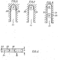
- the spacers 10 of FIGS. 3 to 8 have retaining projections of different designs.
- the holding projections 24 are strips projecting into the slot 11 on both sides and form clamping points 25 for a fastening screw 12 along their length, so that the spacer 10 can be brought into several layers.
- the spacer 10 clamps on the fastening screw 12, and maintains the position given when plugging in.
- the holding projections 24 are at a distance a from the slot end 26, which is dimensioned so large that the fastening screw 12 lies in the slot 11 without clamping, so that the spacer 10 is correspondingly movable, but without the spacer 10 could fall off the fastening screw 12.
- the latter is also the case with the design of the slot 11 according to FIG. 4, the retaining projections 27 of which are also arranged at a distance a from the slot end 26 and only ensure that the spacer disc falls off a fastening screw 12, but not its clamping over the entire slot length.
- the clamping projections 28 of the spacer 10 according to FIG. 5 clamp a fastening screw 12 at a certain point shortly before the slot end 26.
- the holding projections 29, 30, 31 of the spacers 10 of FIGS. 6 to 8 each ensure a relatively easy position of the fastening screw 12 in the slot 11, the holding projections 29 being designed in a spring-like manner in order to insert the fastening screw 12 or to slide the D is -
- cam-like holding projections 30 protrude into the slot 11 and thereby form a particularly simple embodiment.
- the holding projections 31 of the spacer disk according to FIG. 8 are formed over practically the entire length of the slot 11, similar to the holding projections 24. However, they are not present over the entire height h of the spacer 10 at the slot edges 11 ", but only over part of the same, so that they can escape more easily when the spacer is attached to a fastening screw 12 and thus make it easier to slide on.
- the spacer 10 of FIG. 9 has a slot 11 with spring tongues 32 protruding similar to FIG. 6, which engage at the slot end 11 'on the slot edges 11 "of the spacer 10. They close the slot 11 almost so that a small fastening screw 12 does not can slip out of the wide slot 11 and the spacer 10 consequently falls down.
- the spring tongues 32 form with their mutually facing sides an inlet funnel and recede into the recesses 32 'when the spacer 10 is pushed onto the fastening screw 12.
- the recesses 33' are formed so that the diameter of the fastening screw 12 can be practically equal to the slot width w of the slot 11 without the spring tongues 32 pushing the Di impeller 10 hinder insurmountable.
Landscapes
- Engineering & Computer Science (AREA)
- General Engineering & Computer Science (AREA)
- Mechanical Engineering (AREA)
- Civil Engineering (AREA)
- Structural Engineering (AREA)
- Connection Of Plates (AREA)
- Dowels (AREA)
- Turbine Rotor Nozzle Sealing (AREA)
- Separation Using Semi-Permeable Membranes (AREA)
- Laminated Bodies (AREA)
- Glass Compositions (AREA)
- Securing Of Glass Panes Or The Like (AREA)
Priority Applications (1)
| Application Number | Priority Date | Filing Date | Title |
|---|---|---|---|
| AT84105168T ATE27047T1 (de) | 1983-05-31 | 1984-05-08 | Plattenfoermige distanzscheibe. |
Applications Claiming Priority (2)
| Application Number | Priority Date | Filing Date | Title |
|---|---|---|---|
| DE3319661 | 1983-05-31 | ||
| DE19833319661 DE3319661A1 (de) | 1983-05-31 | 1983-05-31 | Plattenfoermige distanzscheibe mit einem schlitz |
Publications (3)
| Publication Number | Publication Date |
|---|---|
| EP0127021A2 true EP0127021A2 (fr) | 1984-12-05 |
| EP0127021A3 EP0127021A3 (en) | 1985-07-10 |
| EP0127021B1 EP0127021B1 (fr) | 1987-05-06 |
Family
ID=6200292
Family Applications (1)
| Application Number | Title | Priority Date | Filing Date |
|---|---|---|---|
| EP84105168A Expired EP0127021B1 (fr) | 1983-05-31 | 1984-05-08 | Disque de distance en forme de plaque |
Country Status (5)
| Country | Link |
|---|---|
| EP (1) | EP0127021B1 (fr) |
| AT (1) | ATE27047T1 (fr) |
| DE (2) | DE3319661A1 (fr) |
| DK (1) | DK159573C (fr) |
| IE (1) | IE55130B1 (fr) |
Cited By (10)
| Publication number | Priority date | Publication date | Assignee | Title |
|---|---|---|---|---|
| EP0171545A1 (fr) * | 1984-07-12 | 1986-02-19 | Hans-Dieter Niemann | Coin d'ajustage pour combler un intervalle dans le bâtiment |
| EP0333293A1 (fr) * | 1988-03-15 | 1989-09-20 | Europrovyl B.V. | Encadrement constitué par un cadre en matière plastique, moyens de fixation ainsi que moyens d'étanchéité |
| GB2220971A (en) * | 1986-04-01 | 1990-01-24 | Hanley Precision Tools | Spacing plates |
| FR2643104A1 (fr) * | 1989-02-10 | 1990-08-17 | Goettgens Sarl Henri | Plaquette pour le calage en position d'un chassis dans une baie de batiment |
| EP0719953A3 (fr) * | 1994-12-31 | 1997-01-22 | Wolfgang Rathsack | Dispositif de mise à niveau pour éléments de construction |
| WO1998035164A1 (fr) | 1997-02-05 | 1998-08-13 | Wolfgang Rathsack | Element de reglage de hauteur |
| EP1939386A1 (fr) | 2008-01-08 | 2008-07-02 | Nina Sun | Cale à fente |
| EP2078800A1 (fr) | 2008-01-08 | 2009-07-15 | Nina Sun | Calage à bride |
| EP2333221B1 (fr) * | 2009-12-04 | 2014-12-31 | Hörmann KG Freisen | Rembourrage arrière pour dormant de porte |
| EP2963223A1 (fr) | 2014-07-03 | 2016-01-06 | Heering Kunststof Profielen B.V. | Plaque d'espacement |
Families Citing this family (1)
| Publication number | Priority date | Publication date | Assignee | Title |
|---|---|---|---|---|
| DE102020112171B4 (de) | 2020-05-06 | 2025-03-06 | Audi Aktiengesellschaft | Ausgleichselement und Verfahren zum Toleranzausgleich beim Einbau eines Bauteils |
Family Cites Families (14)
| Publication number | Priority date | Publication date | Assignee | Title |
|---|---|---|---|---|
| DE8022164U1 (de) * | 1981-05-27 | Philips Patentverwaltung Gmbh, 2000 Hamburg | Geschlitzte Unterlegscheibe zur Halterung eines Leuchtengehäuses | |
| DE7340649U (de) * | 1974-02-21 | Erbsloeh J & A | Vorrichtung zum Befestigen eines als Fenster- bzw. Türrahmen oder als Unterkonstruktion von Fassadenverkleidungen dienenden Profilstabes | |
| DE7128103U (de) * | 1971-10-28 | Fitzner A | Befestigungseinrichtung für Blockfutter, insbesondere von Türrahmen | |
| DE7301452U (de) * | 1973-06-28 | Neumann H | Befestigungslasche zur unsichtbaren Befestigung von Rahmen und Verkleidungen | |
| US1780839A (en) * | 1929-03-30 | 1930-11-04 | Judson C Pewther | Washer |
| US2278708A (en) * | 1939-01-17 | 1942-04-07 | Flex O Tube Company | Method of making fastening devices |
| US2584873A (en) * | 1947-06-25 | 1952-02-05 | Toledo Scale Co | Bearing retaining means |
| DE825163C (de) * | 1949-11-01 | 1951-12-17 | Holzwerke H Wilhelmi | Halter fuer Wandbekleidungsplatten |
| US3221847A (en) * | 1963-04-22 | 1965-12-07 | Warren R Attwood | Structural connections |
| DE1251509B (fr) * | 1964-06-19 | |||
| DE1683548C3 (de) * | 1967-01-05 | 1975-03-06 | Heinz Schuermann & Co, 4800 Bielefeld | Justiervorrichtung für Bauteile wie Rahmen, Platten od.dgl. vorzugsweise von Fertigbauwerken |
| DE6916301U (de) * | 1969-04-22 | 1970-01-02 | Emil Schmitt | Vorrichtung zur befestigung vorgefertigter tuerfutter |
| DE2623803C3 (de) * | 1976-05-28 | 1982-02-18 | Heinz 7121 Pleidelsheim Link | Vorrichtung zum Verankern von Stahlbetonfertigteilen an einem Baukörper |
| DE7737797U1 (de) * | 1977-12-10 | 1978-04-13 | Favorit Tuerenwerke Gmbh & Co Kg, 6052 Muehlheim | Meterrissanker |
-
1983
- 1983-05-31 DE DE19833319661 patent/DE3319661A1/de not_active Withdrawn
-
1984
- 1984-04-27 DK DK212084A patent/DK159573C/da not_active IP Right Cessation
- 1984-05-04 IE IE1116/84A patent/IE55130B1/en not_active IP Right Cessation
- 1984-05-08 EP EP84105168A patent/EP0127021B1/fr not_active Expired
- 1984-05-08 AT AT84105168T patent/ATE27047T1/de not_active IP Right Cessation
- 1984-05-08 DE DE8484105168T patent/DE3463558D1/de not_active Expired
Cited By (13)
| Publication number | Priority date | Publication date | Assignee | Title |
|---|---|---|---|---|
| EP0171545A1 (fr) * | 1984-07-12 | 1986-02-19 | Hans-Dieter Niemann | Coin d'ajustage pour combler un intervalle dans le bâtiment |
| GB2220971A (en) * | 1986-04-01 | 1990-01-24 | Hanley Precision Tools | Spacing plates |
| GB2220971B (en) * | 1986-04-01 | 1990-04-18 | Hanley Precision Tools | Spacing plates |
| EP0333293A1 (fr) * | 1988-03-15 | 1989-09-20 | Europrovyl B.V. | Encadrement constitué par un cadre en matière plastique, moyens de fixation ainsi que moyens d'étanchéité |
| FR2643104A1 (fr) * | 1989-02-10 | 1990-08-17 | Goettgens Sarl Henri | Plaquette pour le calage en position d'un chassis dans une baie de batiment |
| EP0719953A3 (fr) * | 1994-12-31 | 1997-01-22 | Wolfgang Rathsack | Dispositif de mise à niveau pour éléments de construction |
| WO1998035164A1 (fr) | 1997-02-05 | 1998-08-13 | Wolfgang Rathsack | Element de reglage de hauteur |
| US6159575A (en) * | 1997-02-05 | 2000-12-12 | Rathsack; Wolfgang | Height-compensating construction shim |
| EP1939386A1 (fr) | 2008-01-08 | 2008-07-02 | Nina Sun | Cale à fente |
| EP2078800A1 (fr) | 2008-01-08 | 2009-07-15 | Nina Sun | Calage à bride |
| EP2333221B1 (fr) * | 2009-12-04 | 2014-12-31 | Hörmann KG Freisen | Rembourrage arrière pour dormant de porte |
| EP2963223A1 (fr) | 2014-07-03 | 2016-01-06 | Heering Kunststof Profielen B.V. | Plaque d'espacement |
| NL2013119A (en) * | 2014-07-03 | 2016-03-30 | Heering Kunststof Profielen B V | Spacing plate. |
Also Published As
| Publication number | Publication date |
|---|---|
| DK212084D0 (da) | 1984-04-27 |
| IE841116L (en) | 1984-11-30 |
| EP0127021B1 (fr) | 1987-05-06 |
| DE3319661A1 (de) | 1984-12-06 |
| IE55130B1 (en) | 1990-06-06 |
| ATE27047T1 (de) | 1987-05-15 |
| EP0127021A3 (en) | 1985-07-10 |
| DE3463558D1 (de) | 1987-06-11 |
| DK159573B (da) | 1990-10-29 |
| DK212084A (da) | 1984-12-01 |
| DK159573C (da) | 1991-04-02 |
Similar Documents
| Publication | Publication Date | Title |
|---|---|---|
| DE10044273B4 (de) | Klemmlasche für die dachaußenseitige Adaption mit einem Klemm- und Verriegelungsdachprofilblech für Flachdächer | |
| EP0127021B1 (fr) | Disque de distance en forme de plaque | |
| EP0171545A1 (fr) | Coin d'ajustage pour combler un intervalle dans le bâtiment | |
| DE1225835B (de) | Rahmen fuer Fenster, Tueren od. dgl. | |
| EP1948459B1 (fr) | Unite de vitre sur laquelle est montee une languette decorative | |
| DE2744521C3 (de) | Skikantenschärfvorrichtung | |
| DE29607346U1 (de) | Anschlußprofil zwischen Fensterrahmen und Mauerwerksputz im Bereich einer Fensterlaibung | |
| EP2775068B1 (fr) | Dispositif auxiliaire pour la pose de carreaux | |
| DE102013100922A1 (de) | Laufteil zum Führen eines Möbelteils in einer Führungsrichtung über eine Führungsschiene und Möbelbeschlag | |
| EP0539672A1 (fr) | Ferrure pour fixation dans une rainure d'un profilé rétréci des deux côtés | |
| DE8421839U1 (de) | Plattenfoermige distanzscheibe | |
| DE3500258A1 (de) | Gitterwerkdecke, insbesondere reinraumgitterwerkdecke | |
| DE4013459C2 (de) | Befestigungsvorrichtung für eine Abschlußleiste | |
| AT394416B (de) | Eckverbinder fuer zargen u.dgl. | |
| DE2838031A1 (de) | Scheibenhalter fuer jalousiefenster | |
| EP0761900B1 (fr) | Moyen de fixation pour tuiles de toiture | |
| DE2608271C3 (de) | Seitenführungsschiene für eine Lamellenjalousie | |
| DE3001026A1 (de) | Vorrichtung zur befestigung eines beschlages in einem fluegelprofil fuer fenster oder tueren | |
| EP1186723A2 (fr) | Dispositif de fixation pour une façade avec montants et traverses | |
| DE10038067C2 (de) | Firstlattenhalter | |
| DE8315882U1 (de) | Plattenfoermige distanzscheibe mit einem schlitz | |
| CH445595A (de) | Installationskanal zur Verlegung elektrischer Leitungen | |
| DE2408786C2 (de) | Schienenartiges Luftauslaßelement für Raumbelüftungsanlagen | |
| DE1157358B (de) | Vorhangschiene mit mittelbar ansetzbarer Blende | |
| DE3309114A1 (de) | Putzprofilleiste |
Legal Events
| Date | Code | Title | Description |
|---|---|---|---|
| PUAI | Public reference made under article 153(3) epc to a published international application that has entered the european phase |
Free format text: ORIGINAL CODE: 0009012 |
|
| AK | Designated contracting states |
Designated state(s): AT BE CH DE FR GB IT LI LU NL |
|
| PUAL | Search report despatched |
Free format text: ORIGINAL CODE: 0009013 |
|
| AK | Designated contracting states |
Designated state(s): AT BE CH DE FR GB IT LI LU NL |
|
| 17P | Request for examination filed |
Effective date: 19851218 |
|
| 17Q | First examination report despatched |
Effective date: 19860909 |
|
| GRAA | (expected) grant |
Free format text: ORIGINAL CODE: 0009210 |
|
| AK | Designated contracting states |
Kind code of ref document: B1 Designated state(s): AT BE CH DE FR GB IT LI LU NL |
|
| REF | Corresponds to: |
Ref document number: 27047 Country of ref document: AT Date of ref document: 19870515 Kind code of ref document: T |
|
| PG25 | Lapsed in a contracting state [announced via postgrant information from national office to epo] |
Ref country code: LU Free format text: LAPSE BECAUSE OF NON-PAYMENT OF DUE FEES Effective date: 19870531 |
|
| ITF | It: translation for a ep patent filed | ||
| REF | Corresponds to: |
Ref document number: 3463558 Country of ref document: DE Date of ref document: 19870611 |
|
| ET | Fr: translation filed | ||
| PLBE | No opposition filed within time limit |
Free format text: ORIGINAL CODE: 0009261 |
|
| STAA | Information on the status of an ep patent application or granted ep patent |
Free format text: STATUS: NO OPPOSITION FILED WITHIN TIME LIMIT |
|
| 26N | No opposition filed | ||
| PGFP | Annual fee paid to national office [announced via postgrant information from national office to epo] |
Ref country code: LU Payment date: 19900418 Year of fee payment: 7 |
|
| ITTA | It: last paid annual fee | ||
| REG | Reference to a national code |
Ref country code: FR Ref legal event code: CL |
|
| REG | Reference to a national code |
Ref country code: GB Ref legal event code: IF02 |
|
| PGFP | Annual fee paid to national office [announced via postgrant information from national office to epo] |
Ref country code: CH Payment date: 20020416 Year of fee payment: 19 |
|
| PGFP | Annual fee paid to national office [announced via postgrant information from national office to epo] |
Ref country code: NL Payment date: 20020430 Year of fee payment: 19 |
|
| PGFP | Annual fee paid to national office [announced via postgrant information from national office to epo] |
Ref country code: GB Payment date: 20020502 Year of fee payment: 19 Ref country code: AT Payment date: 20020502 Year of fee payment: 19 |
|
| PGFP | Annual fee paid to national office [announced via postgrant information from national office to epo] |
Ref country code: FR Payment date: 20020513 Year of fee payment: 19 |
|
| PGFP | Annual fee paid to national office [announced via postgrant information from national office to epo] |
Ref country code: BE Payment date: 20020527 Year of fee payment: 19 |
|
| PGFP | Annual fee paid to national office [announced via postgrant information from national office to epo] |
Ref country code: DE Payment date: 20020528 Year of fee payment: 19 |
|
| PG25 | Lapsed in a contracting state [announced via postgrant information from national office to epo] |
Ref country code: GB Free format text: LAPSE BECAUSE OF NON-PAYMENT OF DUE FEES Effective date: 20030508 Ref country code: AT Free format text: LAPSE BECAUSE OF NON-PAYMENT OF DUE FEES Effective date: 20030508 |
|
| PG25 | Lapsed in a contracting state [announced via postgrant information from national office to epo] |
Ref country code: LI Free format text: LAPSE BECAUSE OF NON-PAYMENT OF DUE FEES Effective date: 20030531 Ref country code: CH Free format text: LAPSE BECAUSE OF NON-PAYMENT OF DUE FEES Effective date: 20030531 Ref country code: BE Free format text: LAPSE BECAUSE OF NON-PAYMENT OF DUE FEES Effective date: 20030531 |
|
| BERE | Be: lapsed |
Owner name: *NIEMANN HANS-DIETER Effective date: 20030531 |
|
| PG25 | Lapsed in a contracting state [announced via postgrant information from national office to epo] |
Ref country code: NL Free format text: LAPSE BECAUSE OF NON-PAYMENT OF DUE FEES Effective date: 20031201 |
|
| PG25 | Lapsed in a contracting state [announced via postgrant information from national office to epo] |
Ref country code: DE Free format text: LAPSE BECAUSE OF NON-PAYMENT OF DUE FEES Effective date: 20031202 |
|
| GBPC | Gb: european patent ceased through non-payment of renewal fee |
Effective date: 20030508 |
|
| REG | Reference to a national code |
Ref country code: CH Ref legal event code: PL |
|
| PG25 | Lapsed in a contracting state [announced via postgrant information from national office to epo] |
Ref country code: FR Free format text: LAPSE BECAUSE OF NON-PAYMENT OF DUE FEES Effective date: 20040130 |
|
| NLV4 | Nl: lapsed or anulled due to non-payment of the annual fee |
Effective date: 20031201 |
|
| REG | Reference to a national code |
Ref country code: FR Ref legal event code: ST |