EP0127122A2 - Système de commande numérique ayant une unité de visualisation et machine-outil commandée par le système - Google Patents
Système de commande numérique ayant une unité de visualisation et machine-outil commandée par le système Download PDFInfo
- Publication number
- EP0127122A2 EP0127122A2 EP84105878A EP84105878A EP0127122A2 EP 0127122 A2 EP0127122 A2 EP 0127122A2 EP 84105878 A EP84105878 A EP 84105878A EP 84105878 A EP84105878 A EP 84105878A EP 0127122 A2 EP0127122 A2 EP 0127122A2
- Authority
- EP
- European Patent Office
- Prior art keywords
- address
- blocks
- selecting
- menu
- numerical control
- Prior art date
- Legal status (The legal status is an assumption and is not a legal conclusion. Google has not performed a legal analysis and makes no representation as to the accuracy of the status listed.)
- Granted
Links
Images





Classifications
-
- G—PHYSICS
- G05—CONTROLLING; REGULATING
- G05B—CONTROL OR REGULATING SYSTEMS IN GENERAL; FUNCTIONAL ELEMENTS OF SUCH SYSTEMS; MONITORING OR TESTING ARRANGEMENTS FOR SUCH SYSTEMS OR ELEMENTS
- G05B19/00—Program-control systems
- G05B19/02—Program-control systems electric
- G05B19/18—Numerical control [NC], i.e. automatically operating machines, in particular machine tools, e.g. in a manufacturing environment, so as to execute positioning, movement or co-ordinated operations by means of program data in numerical form
- G05B19/4093—Numerical control [NC], i.e. automatically operating machines, in particular machine tools, e.g. in a manufacturing environment, so as to execute positioning, movement or co-ordinated operations by means of program data in numerical form characterised by part programming, e.g. entry of geometrical information as taken from a technical drawing, combining this with machining and material information to obtain control information, named part program, for the NC machine
- G05B19/40931—Numerical control [NC], i.e. automatically operating machines, in particular machine tools, e.g. in a manufacturing environment, so as to execute positioning, movement or co-ordinated operations by means of program data in numerical form characterised by part programming, e.g. entry of geometrical information as taken from a technical drawing, combining this with machining and material information to obtain control information, named part program, for the NC machine concerning programming of geometry
- G05B19/40936—Defining geometry with a high level language
-
- G—PHYSICS
- G06—COMPUTING OR CALCULATING; COUNTING
- G06F—ELECTRIC DIGITAL DATA PROCESSING
- G06F15/00—Digital computers in general; Data processing equipment in general
- G06F15/02—Digital computers in general; Data processing equipment in general manually operated with input through keyboard and computation using a built-in program, e.g. pocket calculators
-
- G—PHYSICS
- G05—CONTROLLING; REGULATING
- G05B—CONTROL OR REGULATING SYSTEMS IN GENERAL; FUNCTIONAL ELEMENTS OF SUCH SYSTEMS; MONITORING OR TESTING ARRANGEMENTS FOR SUCH SYSTEMS OR ELEMENTS
- G05B2219/00—Program-control systems
- G05B2219/30—Nc systems
- G05B2219/36—Nc in input of data, input key till input tape
- G05B2219/36129—Menu keys, function of keys soft defined
-
- Y—GENERAL TAGGING OF NEW TECHNOLOGICAL DEVELOPMENTS; GENERAL TAGGING OF CROSS-SECTIONAL TECHNOLOGIES SPANNING OVER SEVERAL SECTIONS OF THE IPC; TECHNICAL SUBJECTS COVERED BY FORMER USPC CROSS-REFERENCE ART COLLECTIONS [XRACs] AND DIGESTS
- Y02—TECHNOLOGIES OR APPLICATIONS FOR MITIGATION OR ADAPTATION AGAINST CLIMATE CHANGE
- Y02P—CLIMATE CHANGE MITIGATION TECHNOLOGIES IN THE PRODUCTION OR PROCESSING OF GOODS
- Y02P90/00—Enabling technologies with a potential contribution to greenhouse gas [GHG] emissions mitigation
- Y02P90/02—Total factory control, e.g. smart factories, flexible manufacturing systems [FMS] or integrated manufacturing systems [IMS]
Definitions
- the present invention relates to an NC (Numerical Control) system having a display unit such as a CRT (Cathode-Ray Tube) and which is operable on an interactive basis.
- NC Genetic Control
- FIG. 1 of the accompanying drawings illustrates a control panel of a conventional NC system having a CRT
- Fig. 2 shows sections of the control panel in greater detail.
- the control panel has a CRT 1, a display-image selecting key group 2 for selecting display images on the CRT 1, (the key group 2 including a plurality of keys 21 through 28), a data key group (numeric keyboard) 3 for entering data, an address key group 4 composed of alphabetical keys for distinguishing data contents, a data editing key group 5 composed of a plurality of keys 51 through 58 used for editing data entered on the CRT 1, and a mode selecting key group 6 composed of a plurality of keys 61 through 68 used for selecting operating modes of the NC system and a machine being controlled thereby.
- These various keys are associated with respective switches.
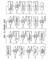
- the operator switches on a power supply in a step (a). Then, the operator decides what to do next dependent on the work to be done by a machining program to be entered in a step (b).
- a program generation switch 66 in the mode selecting key group 6 is depressed in a step (c) for selecting an operating mode in entering the machining program.
- a program switch 23 in the display-image selecting key group 2 is depressed in a step (e) for selecting a display image on the CRT 1, and an image for generating the machining program is displayed on the CRT 1 in a step (f).
- step (g) The operator then decides what to do next in step (g): in this example he depresses a "P" switch which is pre-set in the address key group 4 and a "1" switch, a "6" switch, and a setting switch which are coded in the data key group 3 for setting a program number in a step (h). The operator also depresses a "G” switch in the address key group 4 and an "0” switch and a "setting” switch in the data key group 3 for setting a preparatory function in a step (j).
- step (k) the operator decides what to do next in a step (k), and here depresses an X-switch in the address key group 4 and a "2" switch, a "4" switch, the "6” switch, a “.” switch, a "3” switch, and the "setting” switch in a step (1) to establish that the X coordinate, of a target positioning point is "246.3".
- a "Z” switch in the address key group 4 and the "6” switch, the "2" switch, the “3” switch, the ".” switch, a "5" switch, and the "6” switch in the data key group 3 in a step (n) to establish that the Z coordinate of the target positioning point is "623.56".
- the operator depresses an "M” switch in the address key group 4 and the “3” switch and the "setting” switch in the data key group 3 in a step (p) for setting auxiliary functions such as setting of a spindle and starting and stopping of a coolant, for example. All necessary auxiliary functions set in a step (q) by depressing the "M” switch in the address key group 4 and the numerical keys in the data key group dependent on the auxiliary functions to be set.
- priority G-code execution orders are pre-set such as:
- an operation discriminating means for determining whether a G code is to be executed or not each time it is specified, and an address selecting means for selecting an address required by the determined operating mode from many addresses.
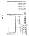
- FIG. 4 shows a control panel employed in accordance with the present invention.
- a CRT 1 has a screen capable of displaying characters in 24 lines and 80 columns and having a message display section 1a, an input data display section 1b, a set data display section 1c, and a menu display section 1d.
- the control panel has a menu selecting key group 11 having a plurality of switches corresponding to items in the menu display section 1d, and a menu incrementing key 12 for manually incrementing menu pages.
- the page of the menu displayed on the menu display section 1d can be renewed by the contents of the menu successively displayed on the message display section 1a or by manually depressing the menu incrementing key 12.
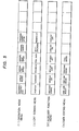
- Fig. 5 illustrates control items for the respective menu pages to be displayed on the menu display section 1d, the control items including an operating mode menu (i), a CRT screen menu (ii), an auxiliary function menu (iii), and a data editing menu (iv).
- Any desired item can be accessed by depressing the switch in the menu selecting key group 11 which corresponds to the desired item in the displayed page.
- the content of the message displayed in the message display section 1a can successively be responded to by entering data into the input data section 1b with a data key group 3, or by selecting the desired control item in the menu displayed on the menu display section 1d while the message is being displayed. Therefore, the operator may proceed with the control operation while being guided by the displayed message and while responding to the same.
- Any page such as of the data editing menu which cannot be displayed on a message-related basis can be displayed manually by depressing the menu incrementing key 12.
- Fig. 7 shows the NC system according to one embodiment of the present invention.
- the NC system has an input unit 121, a central processing unit (CPU) 122, an operation discriminating unit 123 for classifying operating modes as set into modal (hold) and nonmodal (nonholding) and discriminating operating modes to be executed in individual blocks, an address selecting unit 124 for selecting an address corresponding to the discriminated operating mode from among a number of addresses, a data setting unit 125 for setting data,corresponding to the selected address, a machining program storage unit 126 for storing a set machining program, and a display control unit 127 for displaying on a display unit 128 the addresses selected by the address selecting unit 124 as a control item (for example, a head item) and the program stored in the machining program storage unit 126.
- a control item for example, a head item
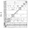
- Fig. 8 shows by way of example a priority execution order of a G code among other operating modes to be discriminated by the operation discriminating unit 123.
- the mark Oin Fig. 8 means execution of a newly specified G code without affecting a previously specified G code
- the mark a means cancelling of a previously specified G code and the execution of a newly specified G code
- the mark ⁇ means execution of a previously specified G code while neglecting a newly specified G code
- the mark X means issuance of an alarm since a newly specified G code is improper.
- G codes can be classified into a group called modal in which a G code once specified is maintained effective until a next particular G code is specified, and a group called nonmodal in which a G code is effective only in a specified block.
- the G codes specified previously in Fig. 8 belong to the modal group and are effective when a new G code is specified.
- Those marked with O are indicative of the use of a newly specified G code in combination with a previously specified G code, as when G00 (positioning), G01 (linear interpolation), G02 (CW arc interpolation), or G03 (CCW arc interpolation) is specified while a plane such as G17 (XY), G18 (ZX), or G19 (YZ) is selected.
- Those marked with ⁇ are indicative of equivalent replacement between a newly specified G code and a previously specified G code, as when specifying G02 (CW arc interpolation) after G01 (linear interpolation).
- Those marked with A are indicative of a newly specified G code producing a contradictory cutting condition as when changing information on tool diameter compensation such as G40 (cancelling of tool diameter compensation), G41 (left-side tool diameter compensation), or G42 (right- side tool diameter compensation) while executing G73 (deep-hole cycle).
- tool diameter compensation such as G40 (cancelling of tool diameter compensation), G41 (left-side tool diameter compensation), or G42 (right- side tool diameter compensation) while executing G73 (deep-hole cycle).
- Those marked with X indicate when a newly specified G code produces contradiction such as a change in a machined shape, as when changing a selected plane such as G17 (XY), G18 (ZX), or G19 (YZ) while executing G02 (CW arc interpolation) or G03 (CCW arc interpolation).
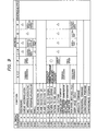
- Fig. 9 shows a relationship between G codes and addresses which is required in the address selecting unit 124 when selecting an address needed by an operating mode discriminated by the operation discriminating unit 123.
- Addresses denoted in the columns X, Y, Z at G00 through G03 for example indicate that their terminal coordinates are set by the G codes.
- Addresses denoted by0 in the column F at G28 through G30 for example indicate that they are renewable by the G codes.
- Addresses denoted by A in the columns I, J, K at G00 through G03 for example indicate that they are unecessary with the G codes.
- Addresses denoted by the blank indicate that specifying the G codes is enough and that no address items need be specified.
- G17, G18 and G19 for selecting planes.
- G90 and G91 for selecting absolute command/incremental commands, or G94 and G95 for selecting asynchronous feeding/synchronous feeding are used for applying meanings to specified data, and are indicated with blanks.
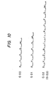
- Fig. 10 shows an example of addresses selected as head items by the address selecting unit 124. Only addresses selected as necessary by the address selecting unit are displayed as head items on the set data display section 1c in Fig. 4 to guide the operator to enter data at the required addresses.
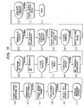
- Fig. 11 is a flowchart of a control procedure to be followed by the operator, the control procedure having steps (a) through (u).
- the CRT 1 When the operator switches on the power supply in the step (a), the CRT 1 automatically displays a message for setting an operating mode, "operating mode ⁇ menu > ?” in the message display section 1a and the operating mode menu shown in Fig. 5 at (i) in the menu display section 1d in the step (b). The operator is guided by the displayed data to select "program generation" from the operating mode menu in Fig. 5 at (i), and depresses the corresponding switch in the menu selecting key group 11 in the step (c). Then, the CRT 1 automatically displays a message "CRT screen ⁇ menu > ?” in the message display section 1a and the CRT screen menu in Fig. 5 at (ii) in the menu display section 1d. The operator selects "program” from the CRT screen menu and depresses the corresponding switch in the menu selecting key group 11 in the step (e).
- the CRT also displays a message for generating the program "program NO ⁇ data > in the message display section 1a in the steps (f) and (g).
- the operator depresses the coded "1" and “6" switches and the "setting” switch in the data key group 3 in the step (h) to enable a program number in the input data display section 1b.
- the program number is thus set, and the CRT displays the message "G code ⁇ menu > ?” in the message display section 1a and the G code menu shown in Fig. 5 at (iii) in the menu display section 1d in the step (i).
- the operator selects "positioning GO" from the G code menu and depresses the corresponding switch in the menu selecting key group 11 in the step (j) to set positioning GO in the step (k).
- the operation discriminating unit 124 determines whether the G code is to be set, and thereafter the CRT displays an address corresponding to the G code as a head item, as shown in Fig. 10.
- the cursor is positioned at an address "X”
- the operator depresses the "2", “4", “6", “.”, “3” keys and the "setting” switches in the data key group 3 to set the terminal X coordinate as "246.4” in the step (1).
- the cursor is positioned at an address "Y”
- the operator depresses the "6", "2", “3", ".”, "5", "6” keys and the "setting” switches in the data key group 3 to set the terminal Z coordinate as "623.56” in the steps (m) and (n).
- the CRT When the cursor reaches an address "M”, the CRT displays a message for setting an auxiliary function, "auxiliary function ⁇ menu > ?" and the auxiliary function menu shown in Fig. 5 in the step (0).
- the operator selects "spindle CW", "coolant ON” or the like as desired from the auxiliary function menu, and depresses the corresponding switch in the menu selecting key group 11 in the step (p).
- the CRT also displays a message "G code ⁇ menu > ?” and "G code” in the menu, and the operator depresses the switch in the menu selecting key group 11 corresponding to "G" and the "1" switch and the "setting” switch in the data selecting key group 3 for establishing linear machining in the step (q) and (r).
- the operator subsequently repeats setting or menu selection while being guided by messages displayed on the basis of a predetermined program format, and depresses switches in the menu selecting key group (11) which correspond to "program ending", “spindle OFF", "coolant off” and others to complete generation of the program in the steps (s), (t) and (u).
- the menus and data successively established in the foregoing manner are displayed as a completed program in the set data display section 1c and the CRT 1.
- messages and the menus are indicated by ordinary words, they may be indicated by symbols or marks.
- Messages may be displayed by a plurality of sentences at one time instead of being displayed successively by single sentences as shown.
- Addresses to be displayed as head items may be displayed as divided as items to be set and items to be responded to as though they have been illustrated undivided.
- ON/OFF conditions of the menus can be distinguished one from the other by reverse display of the characters on the CRT screen, causing them to flicker, or displaying them selectively in upper and lower cases.
- control procedure has been described with reference to the generation of a program, it may be used for ordinary machine control with data setting items removed.
- Fig. 6 illustrates another example of addresses selected as necessary by the address selecting unit which are displayed as control items.
- the illustrated control items are classified as menu groups rather than as G codes as shown in Fig. 5.
- Designated at (a) through (c) and (d) through (f) are menus accessed by the menu incrementing key.
- the operator can set a desired address as a head item in the set data display section 1c in Fig. 4 by using the address selecting unit 124.
- Fig. 12 shows the relationship between addresses and G codes for selecting addresses corresponding to the operating modes discriminated by the address selecting unit 124 from among large number of addresses.
- Menu groups are classified into groups for displaying addresses as menus as illustrated in Fig. 6.
- Those marked with 0 among addresses which are set by G codes are indicative of items to be responded to, and those marked with ⁇ are indicative of items that are unnecessary with the G codes.
- G17, G18 and G19 for selecting planes, G90 and G91 for selecting absolute command/incremental command, or G94 and G95 for selecting asynchronous feeding/synchronous feeding are used for applying meanings to specified data and are indicated with blank.
- Those marked with @ in the column of the modal group are indicative of those set to an initial condition in the modal group.
- Other items include M, S, T, B for specifying individual functions, O for specifying a program number, N for specifying a sequence number, and D, E, H, L for specifying compensation and particular operations such as a variable and others.
- the address menus shown in Fig. 9 are produced on the basis of Fig. 12. At first after the power supply has been switched on, the menu of the menu group A is displayed, and subsequently the menu of the menu group containing a previously used G code is displayed.
- the operator effects and proceeds with patternized control by answering the questions of a displayed message through the setting of data or selection of a menu. Since an operating mode as specified is not immediately registered but registered after whether it should be executed or not has been,determined, modal control is possible in which operation according to a previously registered operating mode is prevented from being affected by a specified operating mode. As only an address necessary with a selected operating mode is displayed, a format check can easily be effected to prevent data shortage or address errors.
- the menu selecting keys have different functions for respective menu pages so that the number of switches on the control panel can greatly be reduced. Because the messages and menus are processed by software, changes and enlargement of the functions are facilitated.
Landscapes
- Engineering & Computer Science (AREA)
- Physics & Mathematics (AREA)
- General Physics & Mathematics (AREA)
- Theoretical Computer Science (AREA)
- Geometry (AREA)
- Human Computer Interaction (AREA)
- Manufacturing & Machinery (AREA)
- Automation & Control Theory (AREA)
- General Engineering & Computer Science (AREA)
- Computer Hardware Design (AREA)
- Computing Systems (AREA)
- Numerical Control (AREA)
- Electrical Discharge Machining, Electrochemical Machining, And Combined Machining (AREA)
Applications Claiming Priority (4)
| Application Number | Priority Date | Filing Date | Title |
|---|---|---|---|
| JP58090270A JPS59229613A (ja) | 1983-05-23 | 1983-05-23 | 数値制御装置 |
| JP90270/83 | 1983-05-23 | ||
| JP90269/83 | 1983-05-23 | ||
| JP58090269A JPS59229612A (ja) | 1983-05-23 | 1983-05-23 | 数値制御装置 |
Publications (3)
| Publication Number | Publication Date |
|---|---|
| EP0127122A2 true EP0127122A2 (fr) | 1984-12-05 |
| EP0127122A3 EP0127122A3 (en) | 1986-04-16 |
| EP0127122B1 EP0127122B1 (fr) | 1989-08-16 |
Family
ID=26431767
Family Applications (1)
| Application Number | Title | Priority Date | Filing Date |
|---|---|---|---|
| EP84105878A Expired EP0127122B1 (fr) | 1983-05-23 | 1984-05-23 | Système de commande numérique ayant une unité de visualisation et machine-outil commandée par le système |
Country Status (4)
| Country | Link |
|---|---|
| US (1) | US4700290A (fr) |
| EP (1) | EP0127122B1 (fr) |
| KR (1) | KR890001314B1 (fr) |
| DE (1) | DE3479451D1 (fr) |
Cited By (7)
| Publication number | Priority date | Publication date | Assignee | Title |
|---|---|---|---|---|
| GB2193011A (en) * | 1986-07-21 | 1988-01-27 | Schlumberger Electronics | Programmable time switch |
| FR2618168A1 (fr) * | 1987-07-14 | 1989-01-20 | Tokai Ind Sewing Machine | Dispositif de positionnement de donnees pour une machine a broder ou une machine a coudre. |
| GB2212946A (en) * | 1987-11-28 | 1989-08-02 | Smith Meters Ltd | Programming devices wlth multifunction controls |
| EP0257099A4 (fr) * | 1986-01-24 | 1990-04-09 | Fanuc Ltd | Dispositif de detection de differentes erreurs dans des valeurs de consigne pour une machine de moulage par injection. |
| EP0478772A4 (en) * | 1988-10-31 | 1992-05-13 | Fanuc Ltd. | Pert program execution method |
| EP0424542A4 (en) * | 1989-05-10 | 1992-12-02 | Fanuc Ltd. | Conversational apparatus for preparing part program |
| GB2276733A (en) * | 1993-03-31 | 1994-10-05 | Mitsubishi Electric Corp | Programmable controller and methods of setting and displaying its internal information |
Families Citing this family (9)
| Publication number | Priority date | Publication date | Assignee | Title |
|---|---|---|---|---|
| US4947315A (en) * | 1986-12-03 | 1990-08-07 | Finnigan Corporation | System for controlling instrument using a levels data structure and concurrently running compiler task and operator task |
| US4918602A (en) * | 1987-07-15 | 1990-04-17 | Computer Associates International, Inc. | Data processing system and method |
| US5099413A (en) * | 1987-12-12 | 1992-03-24 | Sadashiro Sakai | System which reads type and position of task element marks on a matrix of program tasks for automatically generating programs |
| JPH01287707A (ja) * | 1988-05-16 | 1989-11-20 | Mitsubishi Electric Corp | 数値制御装置の加工データの作成方法 |
| JPH0215304A (ja) * | 1988-07-04 | 1990-01-19 | Mitsubishi Electric Corp | 数値制御情報作成方法 |
| JPH0727445B2 (ja) * | 1990-09-04 | 1995-03-29 | インターナショナル・ビジネス・マシーンズ・コーポレイション | コンピュータプロセッサ動作用ユーザインターフェイス |
| DE4329016A1 (de) * | 1993-08-30 | 1995-03-09 | Heidenhain Gmbh Dr Johannes | Verfahren zur Erstellung und/oder Änderung von NC-Programmen |
| US5444634A (en) * | 1994-04-28 | 1995-08-22 | Illinois Tool Works Inc. | Lubricant nozzle positioning system and method |
| US5784281A (en) * | 1996-08-23 | 1998-07-21 | Qcam | Non-graphical automation of machine controls |
Family Cites Families (12)
| Publication number | Priority date | Publication date | Assignee | Title |
|---|---|---|---|---|
| US3816723A (en) * | 1968-07-12 | 1974-06-11 | Houdaille Industries Inc | Machine tool data system and method |
| US3634662A (en) * | 1968-07-12 | 1972-01-11 | Houdaille Industries Inc | Numerical control system and method |
| US4078195A (en) * | 1976-01-13 | 1978-03-07 | Macotech Corporation | Adaptive control system for numerically controlled machine tools |
| JPS5486887A (en) * | 1977-12-22 | 1979-07-10 | Toyoda Mach Works Ltd | Numerical controller |
| US4292666A (en) * | 1978-04-12 | 1981-09-29 | Modicon Div. Gould Inc. | Programmable controller |
| JPS5719809A (en) * | 1980-07-10 | 1982-02-02 | Fanuc Ltd | Numerical control information generating system |
| JPS5731003A (en) * | 1980-08-01 | 1982-02-19 | Fanuc Ltd | Numerical control system |
| JPS57169813A (en) * | 1981-04-13 | 1982-10-19 | Mitsubishi Electric Corp | Numerical controller |
| JPS5882648A (ja) * | 1981-11-05 | 1983-05-18 | Yamazaki Mazak Corp | 数値制御工作機械における工具配列制御方法 |
| JPS58143945A (ja) * | 1982-02-13 | 1983-08-26 | Makino Milling Mach Co Ltd | 金型加工システム |
| JPS58163001A (ja) * | 1982-03-23 | 1983-09-27 | Toyoda Mach Works Ltd | 干渉チエツク機能を備えた数値制御装置 |
| JPS58175003A (ja) * | 1982-04-07 | 1983-10-14 | Fanuc Ltd | 数値制御指令方式 |
-
1984
- 1984-05-23 KR KR8402819A patent/KR890001314B1/ko not_active Expired
- 1984-05-23 EP EP84105878A patent/EP0127122B1/fr not_active Expired
- 1984-05-23 DE DE8484105878T patent/DE3479451D1/de not_active Expired
-
1987
- 1987-01-09 US US07/005,394 patent/US4700290A/en not_active Expired - Lifetime
Cited By (14)
| Publication number | Priority date | Publication date | Assignee | Title |
|---|---|---|---|---|
| EP0257099A4 (fr) * | 1986-01-24 | 1990-04-09 | Fanuc Ltd | Dispositif de detection de differentes erreurs dans des valeurs de consigne pour une machine de moulage par injection. |
| GB2193011A (en) * | 1986-07-21 | 1988-01-27 | Schlumberger Electronics | Programmable time switch |
| GB2193011B (en) * | 1986-07-21 | 1991-01-30 | Schlumberger Ind Ltd | Programmable time switch |
| FR2623530A1 (fr) * | 1987-07-14 | 1989-05-26 | Tokai Ind Sewing Machine | Dispositif de positionnement de donnees pour une machine a broder ou une machine a coudre |
| GB2207780A (en) * | 1987-07-14 | 1989-02-08 | Tokai Ind Sewing Machine | Data setting device for an embroidering machine or other sewing machine |
| FR2618168A1 (fr) * | 1987-07-14 | 1989-01-20 | Tokai Ind Sewing Machine | Dispositif de positionnement de donnees pour une machine a broder ou une machine a coudre. |
| GB2207780B (en) * | 1987-07-14 | 1992-02-12 | Tokai Ind Sewing Machine | Data setting device for an embroidering machine or other sewing machine |
| GB2212946A (en) * | 1987-11-28 | 1989-08-02 | Smith Meters Ltd | Programming devices wlth multifunction controls |
| EP0478772A4 (en) * | 1988-10-31 | 1992-05-13 | Fanuc Ltd. | Pert program execution method |
| EP0424542A4 (en) * | 1989-05-10 | 1992-12-02 | Fanuc Ltd. | Conversational apparatus for preparing part program |
| GB2276733A (en) * | 1993-03-31 | 1994-10-05 | Mitsubishi Electric Corp | Programmable controller and methods of setting and displaying its internal information |
| US5471380A (en) * | 1993-03-31 | 1995-11-28 | Mitsubishi Denki Kabushiki Kaisha | Programmable controller and methods of setting and displaying its internal information |
| GB2276733B (en) * | 1993-03-31 | 1996-05-22 | Mitsubishi Electric Corp | programmable controller and methods of setting and displaying its internal information |
| US5666282A (en) * | 1993-03-31 | 1997-09-09 | Mitsubishi Denki Kabushiki Kaisha | Programmable controller and methods of setting and displaying its internal information |
Also Published As
| Publication number | Publication date |
|---|---|
| DE3479451D1 (en) | 1989-09-21 |
| EP0127122B1 (fr) | 1989-08-16 |
| KR890001314B1 (en) | 1989-04-29 |
| US4700290A (en) | 1987-10-13 |
| KR840008845A (ko) | 1984-12-19 |
| EP0127122A3 (en) | 1986-04-16 |
Similar Documents
| Publication | Publication Date | Title |
|---|---|---|
| EP0127122B1 (fr) | Système de commande numérique ayant une unité de visualisation et machine-outil commandée par le système | |
| EP0120969B1 (fr) | Procede d'introduction d'informations de commande dans un dispositif de commande numerique | |
| EP0076328B1 (fr) | Dispositif de programmation | |
| US5122717A (en) | Apparatus for producing NC programs using menu icons to define operations and producing method thereof | |
| US4648028A (en) | Color enhanced display for a numerical control system | |
| US4587608A (en) | Method of automatically creating numerical control data in one of a plurality of data formats | |
| US4723207A (en) | Machine operator's panel for numerical control | |
| EP0177164A2 (fr) | Méthode et appareil pour la production des programmes pour la commande numérique | |
| US4700313A (en) | Plural turret system with display of permitted and non-permitted simultaneous machining operations | |
| US4797811A (en) | Dual language numerical controller | |
| US10866717B2 (en) | Numerical controller | |
| WO1989006004A1 (fr) | Procede d'introduction des donnees relatives au profil d'une piece | |
| US4697249A (en) | Method and apparatus for creating part program data using a tablet | |
| KR890002435B1 (ko) | 수치 제어방식 | |
| EP0169911A1 (fr) | Systeme de commande numerique | |
| US5457369A (en) | Numerical control system | |
| GB2153122A (en) | Data entry arrangement | |
| JPH06202721A (ja) | 数値制御情報作成装置 | |
| US5072398A (en) | Figure definition method in automatic programming | |
| EP0380700A1 (fr) | Systeme d'affichage de donnees d'usinage | |
| EP0139762A1 (fr) | Procede de specification de la forme d'une ebauche | |
| EP0332703A1 (fr) | Systeme d'introduction de donnees | |
| JPH053002B2 (fr) | ||
| JPH056684B2 (fr) | ||
| JPS6252608A (ja) | 対話型ncプログラム作成方法 |
Legal Events
| Date | Code | Title | Description |
|---|---|---|---|
| PUAI | Public reference made under article 153(3) epc to a published international application that has entered the european phase |
Free format text: ORIGINAL CODE: 0009012 |
|
| AK | Designated contracting states |
Designated state(s): DE FR GB IT |
|
| PUAL | Search report despatched |
Free format text: ORIGINAL CODE: 0009013 |
|
| AK | Designated contracting states |
Kind code of ref document: A3 Designated state(s): DE FR GB IT |
|
| 17P | Request for examination filed |
Effective date: 19860721 |
|
| 17Q | First examination report despatched |
Effective date: 19870911 |
|
| GRAA | (expected) grant |
Free format text: ORIGINAL CODE: 0009210 |
|
| AK | Designated contracting states |
Kind code of ref document: B1 Designated state(s): DE FR GB IT |
|
| REF | Corresponds to: |
Ref document number: 3479451 Country of ref document: DE Date of ref document: 19890921 |
|
| ITF | It: translation for a ep patent filed | ||
| ET | Fr: translation filed | ||
| PLBE | No opposition filed within time limit |
Free format text: ORIGINAL CODE: 0009261 |
|
| STAA | Information on the status of an ep patent application or granted ep patent |
Free format text: STATUS: NO OPPOSITION FILED WITHIN TIME LIMIT |
|
| 26N | No opposition filed | ||
| ITTA | It: last paid annual fee | ||
| REG | Reference to a national code |
Ref country code: GB Ref legal event code: 746 Effective date: 19950523 |
|
| REG | Reference to a national code |
Ref country code: FR Ref legal event code: D6 |
|
| PGFP | Annual fee paid to national office [announced via postgrant information from national office to epo] |
Ref country code: FR Payment date: 19970513 Year of fee payment: 14 |
|
| PG25 | Lapsed in a contracting state [announced via postgrant information from national office to epo] |
Ref country code: FR Free format text: LAPSE BECAUSE OF NON-PAYMENT OF DUE FEES Effective date: 19980531 |
|
| REG | Reference to a national code |
Ref country code: FR Ref legal event code: ST |
|
| PGFP | Annual fee paid to national office [announced via postgrant information from national office to epo] |
Ref country code: GB Payment date: 20010523 Year of fee payment: 18 |
|
| REG | Reference to a national code |
Ref country code: GB Ref legal event code: IF02 |
|
| PG25 | Lapsed in a contracting state [announced via postgrant information from national office to epo] |
Ref country code: GB Free format text: LAPSE BECAUSE OF NON-PAYMENT OF DUE FEES Effective date: 20020523 |
|
| GBPC | Gb: european patent ceased through non-payment of renewal fee |
Effective date: 20020523 |
|
| PGFP | Annual fee paid to national office [announced via postgrant information from national office to epo] |
Ref country code: DE Payment date: 20030605 Year of fee payment: 20 |