EP0127158A1 - Procédé et appareillage pour la détermination du vecteur de flux d'une machine à champ tournant d'après le courant stator et la tension stator et utilisation de ceux-ci - Google Patents
Procédé et appareillage pour la détermination du vecteur de flux d'une machine à champ tournant d'après le courant stator et la tension stator et utilisation de ceux-ci Download PDFInfo
- Publication number
- EP0127158A1 EP0127158A1 EP84105988A EP84105988A EP0127158A1 EP 0127158 A1 EP0127158 A1 EP 0127158A1 EP 84105988 A EP84105988 A EP 84105988A EP 84105988 A EP84105988 A EP 84105988A EP 0127158 A1 EP0127158 A1 EP 0127158A1
- Authority
- EP
- European Patent Office
- Prior art keywords
- vector
- emf
- flow
- component
- angle
- Prior art date
- Legal status (The legal status is an assumption and is not a legal conclusion. Google has not performed a legal analysis and makes no representation as to the accuracy of the status listed.)
- Granted
Links
- 239000013598 vector Substances 0.000 title claims abstract description 317
- 230000004907 flux Effects 0.000 title claims description 45
- 238000000034 method Methods 0.000 title claims description 34
- 230000006698 induction Effects 0.000 title claims description 27
- 230000010354 integration Effects 0.000 claims abstract description 24
- 230000006870 function Effects 0.000 claims description 17
- 238000009499 grossing Methods 0.000 claims description 14
- 230000001419 dependent effect Effects 0.000 claims description 5
- 230000009466 transformation Effects 0.000 claims description 5
- 230000001131 transforming effect Effects 0.000 claims description 4
- 238000011144 upstream manufacturing Methods 0.000 claims description 3
- 230000001052 transient effect Effects 0.000 claims 2
- 238000013016 damping Methods 0.000 abstract description 3
- 230000004069 differentiation Effects 0.000 abstract description 3
- 230000000087 stabilizing effect Effects 0.000 abstract 1
- 230000015572 biosynthetic process Effects 0.000 description 7
- 230000008569 process Effects 0.000 description 7
- 230000000694 effects Effects 0.000 description 5
- 230000001105 regulatory effect Effects 0.000 description 4
- 230000000717 retained effect Effects 0.000 description 4
- 230000008859 change Effects 0.000 description 3
- 238000006243 chemical reaction Methods 0.000 description 3
- 238000005259 measurement Methods 0.000 description 3
- 238000009795 derivation Methods 0.000 description 2
- 238000001514 detection method Methods 0.000 description 2
- 230000007704 transition Effects 0.000 description 2
- 230000001133 acceleration Effects 0.000 description 1
- 230000004913 activation Effects 0.000 description 1
- 230000003321 amplification Effects 0.000 description 1
- 230000033228 biological regulation Effects 0.000 description 1
- 238000004364 calculation method Methods 0.000 description 1
- 230000001276 controlling effect Effects 0.000 description 1
- 230000003247 decreasing effect Effects 0.000 description 1
- 230000005284 excitation Effects 0.000 description 1
- 230000001939 inductive effect Effects 0.000 description 1
- 230000003993 interaction Effects 0.000 description 1
- 238000012544 monitoring process Methods 0.000 description 1
- 238000003199 nucleic acid amplification method Methods 0.000 description 1
- 230000002787 reinforcement Effects 0.000 description 1
- 239000000523 sample Substances 0.000 description 1
- 230000001360 synchronised effect Effects 0.000 description 1
- 230000003313 weakening effect Effects 0.000 description 1
Images


Classifications
-
- H—ELECTRICITY
- H02—GENERATION; CONVERSION OR DISTRIBUTION OF ELECTRIC POWER
- H02P—CONTROL OR REGULATION OF ELECTRIC MOTORS, ELECTRIC GENERATORS OR DYNAMO-ELECTRIC CONVERTERS; CONTROLLING TRANSFORMERS, REACTORS OR CHOKE COILS
- H02P21/00—Arrangements or methods for the control of electric machines by vector control, e.g. by control of field orientation
- H02P21/14—Estimation or adaptation of machine parameters, e.g. flux, current or voltage
- H02P21/141—Flux estimation
-
- H—ELECTRICITY
- H02—GENERATION; CONVERSION OR DISTRIBUTION OF ELECTRIC POWER
- H02P—CONTROL OR REGULATION OF ELECTRIC MOTORS, ELECTRIC GENERATORS OR DYNAMO-ELECTRIC CONVERTERS; CONTROLLING TRANSFORMERS, REACTORS OR CHOKE COILS
- H02P21/00—Arrangements or methods for the control of electric machines by vector control, e.g. by control of field orientation
- H02P21/06—Rotor flux based control involving the use of rotor position or rotor speed sensors
- H02P21/10—Direct field-oriented control; Rotor flux feed-back control
Definitions
- the invention relates to a method for determining the flux vector of a three-phase machine from stator current and stator voltage with the features of the preamble of claim 1.
- the invention further relates to an apparatus for performing the method and an application.
- Such a method is used in the device according to German Offenlegungsschrift 30 26 202 for the field-oriented operation of an inverter-fed induction machine.
- the position of the flux vector is detected and the converter feeding the machine is controlled as a function of the position of the flux vector so that the component of the stator current parallel to the flux and the stator current component perpendicular thereto can be influenced independently.
- a predetermined value for the amount of the flux can be set via the control of the stator current component parallel to the flux (magnetizing current), while the current component (active current) perpendicular to the flux then enters the torque linearly and can be used directly for the decoupled control of speed or torque.
- Flat vectors can be used to describe the machine currents, machine voltages, the EMF and the flux, each with two parameters, for example their Cartesian or polar components with respect to a stationary (ie stator-oriented or “fixed") or rotating with the rotor axis (“rotor-oriented”) or the field axis rotating (“field-oriented”) coordinate system.
- the Cartesian stand-oriented components of the flux vector ⁇ s then each result as an integral of the corresponding component of the EMF vector.
- the EMF vector In a coordinate system rotating with the flow vector with the coordinate axis ⁇ 1 parallel to the field and the coordinate axis ⁇ 2 perpendicular to the field, the EMF vector has the "Field-oriented" components ⁇ 4 and e ⁇ 2
- ⁇ ⁇ e ⁇ dt
- the voltage model is therefore always stator-oriented.
- the open integrators required for EMF integration tend to drift away and have to be stabilized, e.g. via a zero point controller located in a feedback line of the integrator. With the zero point drift of the integrators, however, the corresponding slow changes in the flow components are also suppressed at low operating frequencies. In addition, an angular error occurs in stationary operation, which also affects above all at low frequencies and leads to a disruptive misorientation if the setpoints for the stator current are specified in a field-oriented manner. However, these disadvantages are offset by the good dynamics of this voltage model.
- a model value for the machine flow from the machine currents (i.e. the stator current vector Lund and in the case of a synchronous machine also the excitation current cm iQ) and the measured rotor position ⁇ or, which is often advantageous from a measurement point of view, from the rotor speed ⁇ .
- This "current model” electronically simulates the processes occurring in the machine, insofar as they lead to the formation of the flow.
- the ver Use of a field-oriented coordinate system is advantageous, the rotor time constant being taken into account as the time constant of a smoothing element and the current model forming a model flow frequency from which the flow angle can be formed by integration.
- model parameters that are as precise as possible must be set for the machine parameters, so that e.g. Temperature-related changes in rotor resistance lead to falsifications of the model flow in both stationary and dynamic processes.
- the voltage model is therefore preferable for higher operating frequencies, but at low operating frequencies the current model leads to a better model value for the flow despite possible stationary inaccuracies.
- the controllers therefore receive the Cartesian spatially fixed components of the difference vector ⁇ s (u) - ⁇ s at their inputs and supply the Cartesian spatially fixed components of a correction vector, by means of which the difference vector is corrected on average by the voltage model.
- This ensures that the voltage model tracks the current model, at least with regard to its stationary behavior, so that the good dynamics of the voltage model are retained, but the steady flow determination of the current model, which is better at low frequencies, is used.
- the outputs of the two known correction controllers represent the Cartesian stand-oriented components of a correction vector which essentially rotates at the frequency of the vector ⁇ s .
- the controllers must therefore constantly process alternating variables, which can be disadvantageous not only at high operating frequencies and is particularly difficult when the method is to be carried out with a microprocessor.
- the object of the invention is therefore to create another possibility for determining the flux vector of a induction machine.
- the invention also assumes that the EMF vector of the induction machine is formed from the voltage and current by means of an EMF detector, which is then modified by means of a feedback signal derived from the determined flux vector in order to convert the flux vector by integrating the modified EMF vector to build.
- a rotating orthogonal coordinate system is used to modify the EMF vector, in which the EMF components are processed further. Since the one coordinate axis ultimately, as will be explained, points in the direction of the flow vector, the transformed EMF vector thus has the orthogonal components e ⁇ 1 and e ⁇ 2 .
- the flux vector is now formed from this modified EMF using a special integration process.
- FIG. 1 a control loop is shown in FIG. 1 with an operational amplifier 1 which is understood to be a very fast-acting controller, the output variable Z of which is applied via a negative feedback loop with the gain factor y of the controller input variable X.
- V denotes the gain of the open integration amplifier 1
- this circuit results in the mathematical structure given next, for which the following applies If the reinforcement is large enough, this results thus ultimately a division, as is also shown in FIG.
- FIG. 2 shows a circuit for the formation of the flux components ⁇ ⁇ 1 , ⁇ ⁇ 2 in a reference system rotating with the (initially arbitrary) frequency 305i s , with the respective instantaneous angle of rotation between the spatially fixed coordinate system (axes s 1 , s2) and the rotating coordinate system ( ⁇ 1, ⁇ 2) defining angle signal ⁇ s is formed from a corresponding frequency signaltechnik s by an integrator 2.
- this angle s ⁇ forms a vector rotator 3 of the stator-oriented emf components e s1, s s2, the transformed components e ⁇ 4, e ⁇ 2, it being particularly advantageous from the angle s ⁇ means of an angle function generator 4, the trigonometric functions cos ⁇ s, sin ⁇ s , that is, to form the stand-oriented Cartesian components of a corresponding unit vector zu and to feed them to the vector rotator 3 as a corresponding rotation angle signal pair, so that the vector rotator 3 only has to carry out a few simple algebraic operations.
- FIG. 2 shows the corresponding feedback loops with multipliers 7 and 8.
- of the flow vector is now formed by integrating the first modified EMF component e ⁇ 1 (integrator 5).
- the frequency ⁇ s of the flow vector is formed from the quotient e ⁇ 2 / ⁇ (divider 11). Integrating this frequency (integrator 2) results in the feedback signal ⁇ s , which at the same time defines the angle of rotation of the rotating coordinate system and the direction of the flow vector.
- the stator-oriented polar components of the flow vector have thus already been determined.
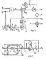
- FIG. 5 now shows how this method can be installed in the field - oriented control of a three-phase machine 21 fed by a converter 20, in this case an asynchronous machine.
- a converter 20 in this case an asynchronous machine.
- the corresponding stator-oriented vectors and u s are formed from measured values for current and voltage, from which the EMF detector 24 forms the stator-oriented EMF vector g s .
- This is achieved in FIG. 5 in that the vector of the ohmic voltage drop and the vector l6 ⁇ di s / dt of the stray voltage drop are formed by means of multiplication 25, 26 and a differentiator 27 and subtracted from the voltage vector at addition points 28 and 29.
- a speed control (speed controller 31) can be provided, for example, which regulates the speed ⁇ , ie the derivation of the angle of rotation supplied by a rotary angle sensor 32, to a corresponding desired value ⁇ *.
- the output signal of the speed controller 31 then supplies the setpoint for the torque to be applied by the machine for maintaining the speed or for the setpoint active current proportional to it .
- Active current is the torque-forming component of the stator current that is perpendicular to the flow.
- the reference variable for this active current can of course also be specified by torque control or regulation or in some other way.
- FIG. 5 it is also indicated by a flux angle controller 33 that the flux of the induction machine can be regulated to a predetermined setpoint
- the output signal of this flow controller 33 then represents the reference variable ready for the "magnetizing current", ie the flux-parallel component of the stator current.
- flux control is often dispensed with and the magnetizing current is predetermined in accordance with a constant flux during normal operation and a decreasing flux in the field weakening range.
- the reference variables for active current and magnetizing current thus represent the Cartesian components of the target stator current in the field-oriented coordinate system (vector ) and it is only necessary to form from these field-oriented reference variables using the information about the flow angle suitable stand-oriented reference variables for the stator current which is impressed on the machine via the converter 20 and its headset 34.
- the control rate 34 has two separate inputs for the amount and the direction (phase) of the stator current vector.
- the manipulated variable for the current amount can be from the field-oriented target vector be formed by means of a vector analyzer 35, which provides the target amount
- * at its amount output and the angle function pair cos at its angle signal output , sin for the set angle ⁇ * ⁇ between the stator current vector and the axis ⁇ 1 ⁇ s (flux axis).
- This setpoint current vector specified in the "field-oriented" coordinate system can be used as a setpoint for a current control, to which the corresponding field-oriented components of the actual current vector are then to be supplied.
- a vector rotator 36 transforms the actual current vector i ⁇ into the field-oriented coordinate system by means of the flow angle Cf, a subsequent vector analyzer 37 supplying the actual amount lil and the field-oriented current angle ⁇ ⁇ (angle between flow and current).
- the amount manipulated variable for the control rate 34 is thus formed, while the corresponding angle controller 39 specifies the frequency manipulated variable such that the field-oriented current angle ⁇ ⁇ becomes equal to the corresponding setpoint value ⁇ * ⁇ .
- the angle ⁇ ⁇ the tangent of the angle or another function of this win kels can be used; in Figure 5, the field-oriented Cartesian coordinate sin ⁇ ⁇ is used, which is due to the vector outputs of the vector analyzers 35 and 37 as the actual value and setpoint.
- Figure 5 is only one example of a field-oriented control, the current being regulated to the field-oriented setpoints in the field-oriented coordinate system, i.e.
- the actual current values are transformed into the field-oriented coordinate system by means of the vector rotator 36 in order to be able to predefine the same values for the controllers 38 and 39.
- the controller 39 can be relieved to a large extent by the field frequency being applied to a downstream addition point 40 in the sense of a precontrol.
- the field-oriented control of the machine ultimately determines the values for the flow amount ⁇ and the flow angle ⁇ s determined according to the invention, the control of the machine.
- the level of the voltage measurement values required for the flow determination is so low that inaccuracies in the flow determination can occur. These inaccuracies are particularly noticeable in steady-state operation with low frequencies, while dynamic processes can still be detected with relative accuracy by the device.
- An arrangement is therefore shown in FIG. 6, in which the switching of reference variables for the magnitude and angle of the flow is carried out in such a way that stationary errors are largely corrected, but the detection of dynamic processes is retained.
- the unit vector a flow guide vector is determined, it is sufficient to adjust the angle ' S by a tracking controller 40 or its unit vector ( A accordingly.
- a tracking controller 40 or its unit vector ( A it is provided to determine the reference variable to use a current model 41 fed from the current actual value and the rotor position angle and transform with a vector rotator 42 into the field-oriented coordinate system. This transformation corresponds to an angular difference formation.
- the command variable can also be determined in a different way, for example from setpoints formed in the field-oriented control.
- the angle tracking controller 40 thus provides the frequency so that the direction of the detected field vector on average through corresponds to the given direction.
- the field frequency can therefore be tapped at the output of the controller 40, while the field direction (i.e. the one coordinate axis of the field-oriented coordinate system) is formed by integration (integrator 43) and subsequent formation of the angular functions cos ⁇ s , sin ⁇ s (function generator 44).
- FIG. 6 shows that the direction information obtained in this way can be used, for example, to transform the stator voltage vector or other quantities from the stator-oriented to the field-oriented coordinate system, insofar as this requires the field-oriented control of the machine (vector rotator 36).
- the angle tracking controller 40 Since the angle tracking controller 40 already supplies the field-oriented direction of the flow vector, the elements 2 and 11 still required in FIG. 5 to determine this direction can be omitted in this circuit. However, this means that the feedback signal derived from the output of the integrator 5 now disengages and is therefore no longer required. However, the integrator 5 now only delivers the integral of the field-parallel EMF component, which is mathematically not the same as the flow amount. This error can, however, be corrected in a stationary manner in that the integrator output is fed to a subtraction point 45, which supplies the control difference for an amount tracking controller 46, to which the amount control variable ⁇ * is supplied as a setpoint. The output signal of this amount tracking controller 46 is applied to the input of the integrator 5 together with the field-oriented EMF component e ⁇ 1 .
- a circuit is obtained in which the stand-oriented EMF vector! S supplied by the EMF detector 24 is modified in that the EMF vector e s into the rotating coordinate system is determined by means of the signal ⁇ s defining a rotating orthogonal coordinate system is transformed (vector rotator 3) and the feedback signal ⁇ * (output signal of the amount tracking controller 46) is added to the field-parallel component e ⁇ 1 of the transformed EMF vector.
- the amount of the flow vector is then formed by integrating this modified EMF component and the amount feedback signal itself is determined from the system deviation of the amount and the amount control variable.
- This smoothed EMF vector formed by the assembly 55 now has a time behavior which in itself would falsify the formation of the flow vector as an integral of the EMF vector.
- the integration time constant T to be introduced for all integrations for reasons of standardization has an effect here, as everywhere in the circuits under consideration, only as a proportionality factor, which need not be discussed in more detail.
- the integration in the assembly 58 can also be formed in the manner already described in connection with FIGS. 1 to 4 by transforming the smoothed EMF vector into the rotating reference system (vector rotator 3) and subsequent integration in this rotating reference system. This is shown in FIG. 8.
- the angle of rotation required for the transformation at the angle signal input of the vector rotator 3 is formed from the integral of the feedback signal, which consists of the second component and the first component, integrated by means of the integrator 5, of the modified EMF vector tapped at terminal 60 . Since elements 2 to 5 and 11 are the integral of the vector e s form, the output signal of the integrator 5 is the amount of the smoothed flux vector ge Liebe s belonging to the smoothed EMF. Accordingly, the integrator 2 or the function generator 4 supplies the directional angle ⁇ s or the associated unit vector ⁇ s of the smoothed flow vector, which deviates from the direction ⁇ s of the actual (unsmoothed) flow vector in dynamic processes due to the smoothing effect of the assembly 55.
- the first rotating EMF component applied to terminal 60 corresponds e ⁇ 1 the component of the smoothed E M K lying perpendicular to the smoothed flow, while the second component e ⁇ 2 corresponds to the corresponding component of the smoothed EMF perpendicular to the smoothed flow vector T S.
- the effect of the smoothing can now be compensated for by means of the multiplier 61 and the adder 62, in that the quantity supplied by the integrator 5, which is the amount of the smoothed flow vector equal to the component of this vector parallel to the smoothed flow vector, is added to the quantity t e ⁇ 1 So one of the smoothing time constant t and the first component (e ⁇ 1 ) of the modified EMF vector proportional signal. This makes the first component ⁇ ⁇ 1 of the flow vector in the coordinate system ⁇ 1 , ⁇ 2 educated.
- the second component of the smoothed flow vector is zero in this coordinate system, the second component of the unsmoothed flow vector can be directly at the output of multiplier 63 as one of the smoothing time constant and the second component e ⁇ 2 of the modified EMF vector proportional signal can be tapped.
- the Cartesian components of the actual flow vector are thus available at the output of the assembly 58, but in a coordinate system oriented to the smoothed flow vector.
- a vector analyzer 64 can use this to determine the actual flow amount ⁇ and the angle difference between the actual flow vector and the smoothed flow vector, ie the angle ⁇ ⁇ or its Cartesian components cos ⁇ oriented to the smoothed flow angle ⁇ and sin ⁇ ⁇ determine.
- the stand-oriented actual flow direction ⁇ s then results as the sum of angles ⁇ ⁇ + ⁇ s (Vector rotator 65).
- the frequency of the actual flow vector is required, it must be derived from the frequency of the smoothed flow vector and the derivative of the win - kels ⁇ ⁇ be determined. However, the frequency corresponding to this derivative is rarely more than 1 '/ .. of the smoothed flow frequency. If this frequency is only required, for example, for precontrol of an angle control according to FIG. 5 or for the damping circuit explained below, this additional frequency can be neglected, so that the frequency of the smoothed flow vector can be used with good approximation as the flow frequency.
- Integrators generally tend to drift away from their zero point and to other integration errors, which are particularly noticeable at low frequencies (stationary and quasi-stationary states of the induction machine).
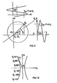
- the position curve of the flow vector ⁇ s is given in the stand-oriented coordinate system sl, s2 for the case that the induction machine works stationary, but the integrators used are subject to a zero point shift.
- the locus of the determined flow vector is then eccentric, ie the center 0 of the locus is shifted by a vector ⁇ from the coordinate origin 0 0 , the "constant component" of the flow vector.
- the flow vector components calculated by the circuit are then mixed quantities in which the sinusoidal movement of the stator-oriented Cartesian coordinates of the actual machine flow is superimposed on the respective Cartesian component of the DC component 4.
- a correction vector ⁇ is advantageously added to the EMF vector, which is derived from the flux vector in such a way that it becomes zero when the flux vector ⁇ s rotates uniformly, and a DC component in when the induction machine is operating in stationary mode the fixed locus of the river vector is suppressed.
- the amount of the correction Turvectors should therefore be proportional to a "volatile quantity" of the flow vector, whereby a volatile quantity is understood to mean a quantity of the flow vector that disappears with a central locus curve (uniform circulation).
- Such a volatile quantity is, for example, the angular acceleration ⁇ s of the flow vector, which is positive above the lines O o -o drawn in dashed lines in FIG. 9 with a positive circulation and negative in the half-plane below O o -o.
- Another preferred volatile variable is the time derivative of the flow amount, with the sign being reversed.
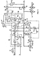
- an amount tracking controller 70 and an angle tracking controller 71 and a changeover switch 72 are introduced as new elements. If the two regulators 70, 71 are disengaged by closing their short-circuit switches and the changeover switch 72 is placed in the position shown, the configuration explained in FIG. 8 can be seen again.
- the EMF detector 55 which forms the EMF vector or the smoothed vector from measured values of current and voltage, is preceded by a DC component control which determines the DC components in the components of the voltage vector with a relatively low gain and subtracts them component by component from the voltage vector .
- This DC component control 73 is so weak that it causes practically no phase distortion of the voltage vector.
- a computing stage 74 is connected downstream of the EMF detector, which supplies the modified EMF vector and contains the vector rotator 3, which forms the orthogonal EMF components in a rotating coordinate system that is rotated by the angle of rotation compared to the stand-oriented coordinate system ⁇ s is rotated.
- the integration stage 58 follows the computing stage 74, the integrator 5 of which increases the amount of the flow vector (in this case) next gives the amount of the smoothed flow vector).
- the angle of rotation ⁇ s in turn is supplied by an angle signal generator, which contains the second integrator 2 and, if angle function pairs are always used as angle signals, also contains the function generator 4.
- the input signal of this integrator is the signal Ü fed back by the integration stage 58, which indicates the frequency of the smoothed flow vector.
- the correction vector ⁇ explained above is supplied by a correction vector generator.
- the correction vector generator need only contain a signal line with a differentiator 76 'branching off at the magnitude output of the vector analyzer 64. This differentiation is also generally superfluous, since the derivation of the flow amount essentially corresponds to the input signal of the integrator 5 and therefore the amount of the correction vector can be tapped with sufficient accuracy on the corresponding component of the transformed EMF vector or of the modified EMF vector .
- the correction vector not only achieves a constant component control, but also dampens the entire flux detection device. However, the dynamics of the river determination is thereby changed. worsened. However, this can be avoided by not determining the amount of the correction vector by itself, but from the difference ⁇ - ⁇ *, where ⁇ * is a reference variable for the change in the flow. In particular, ⁇ * can be tapped from the current model mentioned at the beginning or from the setpoints of the induction machine control.
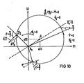
- FIG. 12 shows the field-oriented locus curve of an advantageous predetermined control vector ⁇ ⁇ for the individual values of the flow frequency ⁇ s or specified.
- the specification of the angle ⁇ ⁇ between the correction vector ⁇ and the flow vector by the programmed locus according to FIG. 12 means that the correction vector in the rotating coordinate system is based on the control vector ⁇ ⁇ , the amount of which is modified by multiplication by the volatile variable.
- the correction vector thus formed does not only have one of ⁇ or dependent angle, but its amount is proportional to the volatile variable via a proportionality factor that also depends on ⁇ (namely the function-dependent predetermined amount of the control vector).
- the device according to FIG. 11 is used to intervene in the control of the induction machine with the determined flow vector, it may prove to be advantageous to also change this locus of the control vector ⁇ ⁇ depending on the operation.
- the intervention via the state variable W can possibly have the effect that the correction vector after notification of a circulation of the flow vector on the locus is no longer antiparallel to the DC component vector and therefore this DC component vector is not corrected correctly, but nevertheless through the interaction with the machine and its control stable stationary machine operation is achieved.
- the negative branch in the local curve according to FIG. 12 relates to the case where the flow circulates in a mathematically negative sense.
- the size ⁇ is positive in the top left half and negative in the other half level, so that the same direction of the control vector results in both half levels.
- control vector ⁇ corresponding to FIG. 12 ⁇ biw. ⁇ ⁇ can accordingly take place in the device according to FIG. 11 through a function memory 75 (PROM) which is based on the input signal of the second integrator 2 and possibly controlled by the load angle of the induction machine or another operating variable W of the induction machine.
- PROM function memory 75
- This control vector can then be used component by component with - respectively. or with a multiple multiplied by the reference variable ⁇ * - be adorned in order to then be fed to an addition point 77 in the computing circuit 74.
- the outputs of the integration stage 58 represent the Cartesian components of the unsmoothed flow vector oriented on the smoothed flow vector.
- the conversion of the Cartesian components into polar components or the conversion into other coordinate systems presents no difficulties.
- the vector analyzer 64 determines the magnitude coordinate Y and the angle coordinate ⁇ ⁇ (processed as a unit vector).
- an actual vector or a target vector for example in a rotating field machine control according to FIG. 6 the stator current vector i s
- transformation by means of the vector rotator 81 ins which is acted upon by% ⁇ -Coordinate system and by means of a vector rotator 82 can be transformed into the stand-oriented coordinate system in order to be subsequently processed in the induction machine control.
- the angle difference is formed by a vector rotator 83, of which, however, only one component, for example the component sin ( ⁇ s * - for controlling the angle tracking controller 71, ⁇ s ) is needed.
- This controller regulates the difference ⁇ * - ⁇ in accordance with an absolute value variable ⁇ * and the flow amount W tapped at the output of the integrator 5 in that it is the component the modified EMF vector applies its controller output signal.
- the device according to the invention can be used both independently of the control of a induction machine to control the flow of the induction machine for Justie monitoring and control purposes. It can also be used to intervene in the machine control in the upper frequency range, but in standby mode in the lower speed range, if the machine is then controlled in another way (eg using a current model).
- the command variables ⁇ s *, T and ⁇ * By appropriately specifying the command variables ⁇ s *, T and ⁇ *, it can be achieved that in the lower speed range, in which the low voltage level of the voltage values per se makes the use of the voltage model more difficult, the voltage model is steadily determined by the command variables (eg a current model), the voltage model dynamically correctly records dynamic deviations from the steady state.
- the transition from the state guided by the command variables to the unguided state can be done discontinuously by simply switching the switch 72 to the state shown in FIG. 11, but a continuous transition is also possible, in which the switch 72 alternates with a frequency-dependent duty cycle is switched.
Landscapes
- Engineering & Computer Science (AREA)
- Power Engineering (AREA)
- Control Of Ac Motors In General (AREA)
Priority Applications (1)
| Application Number | Priority Date | Filing Date | Title |
|---|---|---|---|
| AT84105988T ATE21599T1 (de) | 1983-05-27 | 1984-05-25 | Verfahren und vorrichtung zur bestimmung des flussvektors einer drehfeldmaschine aus staenderstrom und staenderspannung und deren anwendung. |
Applications Claiming Priority (4)
| Application Number | Priority Date | Filing Date | Title |
|---|---|---|---|
| DE3319350 | 1983-05-27 | ||
| DE19833319350 DE3319350A1 (de) | 1983-05-27 | 1983-05-27 | Verfahren und vorrichtung zum ermitteln von bestimmungsgroessen des flussvektors einer drehfeldmaschine |
| DE3418641 | 1984-05-18 | ||
| DE3418641 | 1984-05-18 |
Publications (2)
| Publication Number | Publication Date |
|---|---|
| EP0127158A1 true EP0127158A1 (fr) | 1984-12-05 |
| EP0127158B1 EP0127158B1 (fr) | 1986-08-20 |
Family
ID=25811092
Family Applications (1)
| Application Number | Title | Priority Date | Filing Date |
|---|---|---|---|
| EP84105988A Expired EP0127158B1 (fr) | 1983-05-27 | 1984-05-25 | Procédé et appareillage pour la détermination du vecteur de flux d'une machine à champ tournant d'après le courant stator et la tension stator et utilisation de ceux-ci |
Country Status (4)
| Country | Link |
|---|---|
| US (1) | US4593240A (fr) |
| EP (1) | EP0127158B1 (fr) |
| DE (1) | DE3460506D1 (fr) |
| IN (1) | IN164784B (fr) |
Cited By (9)
| Publication number | Priority date | Publication date | Assignee | Title |
|---|---|---|---|---|
| EP0161616A3 (en) * | 1984-05-18 | 1986-12-30 | Siemens Aktiengesellschaft Berlin Und Munchen | Method and device for stabilizing the local curve of a vector formed by integration |
| EP0274716A1 (fr) * | 1987-01-09 | 1988-07-20 | Siemens Aktiengesellschaft | Méthode et appareil à déterminer le vecteur de flux d'une machine à induction |
| FR2614481A1 (fr) * | 1987-02-13 | 1988-10-28 | Pk I | Procede de commande d'un moteur asynchrone et entrainement electrique mettant ce procede en application |
| EP0290890A1 (fr) * | 1987-05-12 | 1988-11-17 | Siemens Aktiengesellschaft | Méthode et appareil à déterminer numériquement l'angle de champ d'une machine à induction |
| EP0317870A1 (fr) * | 1987-11-27 | 1989-05-31 | Siemens Aktiengesellschaft | Méthode et dispositif pour le calcul d'une fonction différentielle |
| EP0179356B1 (fr) * | 1984-10-20 | 1990-11-14 | Asea Brown Boveri Aktiengesellschaft | Procédé et dispositif de régulation d'une machine à champ tournant |
| US5162727A (en) * | 1989-12-02 | 1992-11-10 | Abb Stromberg Drives Oy | Method and apparatus of determining the stator flux estimate of an electric machine |
| DE19618723A1 (de) * | 1995-12-29 | 1997-07-03 | Tech Gmbh Antriebstechnik Und | Kompensierte feldorientierte Regelung |
| EP2846455A1 (fr) * | 2013-09-06 | 2015-03-11 | ABB Technology AG | Procédé et appareil d'estimation d'un flux de stator dans une machine à induction électrique |
Families Citing this family (15)
| Publication number | Priority date | Publication date | Assignee | Title |
|---|---|---|---|---|
| US4698577A (en) * | 1986-01-16 | 1987-10-06 | General Electric Company | Method of digital flux reconstruction with DC elimination |
| GB8603800D0 (en) * | 1986-02-15 | 1986-03-19 | Brown J E | Vector control system |
| DE3812314C2 (de) * | 1987-04-13 | 1994-05-11 | Hitachi Ltd | Steuerverfahren für einen Asynchronmotor |
| JP2780263B2 (ja) * | 1988-02-23 | 1998-07-30 | 株式会社明電舎 | 誘導電動機のベクトル制御方法と装置 |
| US4968925A (en) * | 1989-08-07 | 1990-11-06 | General Electric Company | Universal field-oriented controller |
| FI87413C (fi) * | 1989-11-20 | 1992-12-28 | Abb Stroemberg Drives Oy | Foerfarande foer foerhindrande av kippning av en asynkronmaskin |
| JP2708646B2 (ja) * | 1991-04-12 | 1998-02-04 | 三菱電機株式会社 | 同期機の横軸ダンパ時定数測定装置 |
| GB9211685D0 (en) * | 1992-06-03 | 1992-07-15 | Switched Reluctance Drives Ltd | Sensorless rotor position measurement |
| US5541488A (en) * | 1994-04-11 | 1996-07-30 | Sundstrand Corporation | Method and apparatus for controlling induction motors |
| DE19532149A1 (de) * | 1995-08-31 | 1997-03-06 | Siemens Ag | Verfahren und Vorrichtung zur Korrektur einer Flußrichtung eines Modellflusses einer geberlosen, feldorientiert betriebenen Drehfeldmaschine bis zur Frequenz Null |
| DE19724946B4 (de) * | 1997-06-12 | 2005-09-15 | Siemens Ag | Verfahren und Vorrichtung zur Drehzahlregelung einer geberlosen, feldorientiert betriebenen Asynchronmaschine |
| DE10336068B4 (de) * | 2003-08-06 | 2006-04-06 | Siemens Ag | Verfahren zur gesteuerten Einprägung eines Ständerstrom- und eines Drehmoment-Sollwertes für eine stromrichtergespeiste Drehfeldmaschine |
| DE102006042038B3 (de) * | 2006-09-07 | 2008-02-07 | Siemens Ag | Verfahren und Vorrichtung zur sicheren Drehmomentbegrenzung |
| EP2552014A3 (fr) * | 2011-07-28 | 2016-08-17 | Vestas Wind Systems A/S | Procédé de contrôle de position d'une machine électrique sans capteur |
| US9660564B2 (en) * | 2013-05-12 | 2017-05-23 | Infineon Technologies Ag | Optimized control for synchronous motors |
Citations (5)
| Publication number | Priority date | Publication date | Assignee | Title |
|---|---|---|---|---|
| FR2361665A1 (fr) * | 1976-08-10 | 1978-03-10 | Siemens Ag | Circuit pour la formation d'une grandeur electrique proportionnelle a une composante du flux dans une machine a champ tournant |
| EP0019138A1 (fr) * | 1979-05-16 | 1980-11-26 | Siemens Aktiengesellschaft | Dispositif de réglage de charge d'une machine asynchrone alimentée par un convertisseur |
| EP0043973A1 (fr) * | 1980-07-10 | 1982-01-20 | Siemens Aktiengesellschaft | Système d'entraînement d'une machine à champ tournant comportant une machine à champ tournant alimentée par l'intermédiaire d'un onduleur et une commande d'onduleur branchée à deux intégrateurs à tension alternative et au circuit d'un modèle de calcul |
| DE3034275A1 (de) * | 1980-09-11 | 1982-04-22 | Siemens AG, 1000 Berlin und 8000 München | Vorrichtung zum ermitteln der parameterwerte fuer staenderwiderstand, hauptinduktivitaet und streuinduktivitaet einer asynchronmaschine |
| DE3139136A1 (de) * | 1981-10-01 | 1983-04-14 | Siemens AG, 1000 Berlin und 8000 München | Vorrichtung zum bestimmen der frequenz elektrischer wechselgroessen, insbesondere einer drehfeldmaschine |
Family Cites Families (2)
| Publication number | Priority date | Publication date | Assignee | Title |
|---|---|---|---|---|
| DE2833542C2 (de) * | 1978-07-31 | 1980-09-25 | Siemens Ag, 1000 Berlin Und 8000 Muenchen | Drehfeldmaschinenantrieb, bestehend aus einer umrichtergespeisten Drehfeldmaschine, insbesondere Synchronmaschine und einer Stromrichtersteuerung für den eigengetakteten, insbesondere feldorientierten Betrieb dieser Maschine, mit zwei baugleichen Wechselspannungsintegratoren und Verfahren zum Betrieb des Drehfeldmajchinenantriebes |
| DE3203257A1 (de) * | 1982-02-01 | 1983-08-11 | Siemens AG, 1000 Berlin und 8000 München | Vorrichtung zum bestimmen der gemeinsamen frequenz zweier unabhaengig veraenderlicher wechselgroessen, insbesondere bei einer drehfeldmaschine |
-
1984
- 1984-05-25 DE DE8484105988T patent/DE3460506D1/de not_active Expired
- 1984-05-25 EP EP84105988A patent/EP0127158B1/fr not_active Expired
- 1984-05-29 US US06/614,828 patent/US4593240A/en not_active Expired - Fee Related
-
1985
- 1985-04-20 IN IN306/CAL/85A patent/IN164784B/en unknown
Patent Citations (5)
| Publication number | Priority date | Publication date | Assignee | Title |
|---|---|---|---|---|
| FR2361665A1 (fr) * | 1976-08-10 | 1978-03-10 | Siemens Ag | Circuit pour la formation d'une grandeur electrique proportionnelle a une composante du flux dans une machine a champ tournant |
| EP0019138A1 (fr) * | 1979-05-16 | 1980-11-26 | Siemens Aktiengesellschaft | Dispositif de réglage de charge d'une machine asynchrone alimentée par un convertisseur |
| EP0043973A1 (fr) * | 1980-07-10 | 1982-01-20 | Siemens Aktiengesellschaft | Système d'entraînement d'une machine à champ tournant comportant une machine à champ tournant alimentée par l'intermédiaire d'un onduleur et une commande d'onduleur branchée à deux intégrateurs à tension alternative et au circuit d'un modèle de calcul |
| DE3034275A1 (de) * | 1980-09-11 | 1982-04-22 | Siemens AG, 1000 Berlin und 8000 München | Vorrichtung zum ermitteln der parameterwerte fuer staenderwiderstand, hauptinduktivitaet und streuinduktivitaet einer asynchronmaschine |
| DE3139136A1 (de) * | 1981-10-01 | 1983-04-14 | Siemens AG, 1000 Berlin und 8000 München | Vorrichtung zum bestimmen der frequenz elektrischer wechselgroessen, insbesondere einer drehfeldmaschine |
Non-Patent Citations (2)
| Title |
|---|
| PATENTS ABSTRACTS OF JAPAN, Band 5, Nr. 7 (E-41)(679), 17. Januar 1981; & JP-A-55 136 890 (FUJI DENKI SEIZO K.K.) 25.10.1980 * |
| SIEMENS FORSCHUNGS- UND ENTWICKLUNGSBERICHTE, Band 1, Nr. 1/72, 1972, Seiten 184-193, Springer-Verlag, Berlin, DE; F. BLASCHKE: "Das Verfahren der Feldorientierung zur Regelung der Asynchronmaschine" * |
Cited By (10)
| Publication number | Priority date | Publication date | Assignee | Title |
|---|---|---|---|---|
| EP0161616A3 (en) * | 1984-05-18 | 1986-12-30 | Siemens Aktiengesellschaft Berlin Und Munchen | Method and device for stabilizing the local curve of a vector formed by integration |
| EP0179356B1 (fr) * | 1984-10-20 | 1990-11-14 | Asea Brown Boveri Aktiengesellschaft | Procédé et dispositif de régulation d'une machine à champ tournant |
| EP0274716A1 (fr) * | 1987-01-09 | 1988-07-20 | Siemens Aktiengesellschaft | Méthode et appareil à déterminer le vecteur de flux d'une machine à induction |
| US4885519A (en) * | 1987-01-09 | 1989-12-05 | Siemens Aktiengesellschaft | Method and apparatus for determining the flux vector of a rotating-field machine |
| FR2614481A1 (fr) * | 1987-02-13 | 1988-10-28 | Pk I | Procede de commande d'un moteur asynchrone et entrainement electrique mettant ce procede en application |
| EP0290890A1 (fr) * | 1987-05-12 | 1988-11-17 | Siemens Aktiengesellschaft | Méthode et appareil à déterminer numériquement l'angle de champ d'une machine à induction |
| EP0317870A1 (fr) * | 1987-11-27 | 1989-05-31 | Siemens Aktiengesellschaft | Méthode et dispositif pour le calcul d'une fonction différentielle |
| US5162727A (en) * | 1989-12-02 | 1992-11-10 | Abb Stromberg Drives Oy | Method and apparatus of determining the stator flux estimate of an electric machine |
| DE19618723A1 (de) * | 1995-12-29 | 1997-07-03 | Tech Gmbh Antriebstechnik Und | Kompensierte feldorientierte Regelung |
| EP2846455A1 (fr) * | 2013-09-06 | 2015-03-11 | ABB Technology AG | Procédé et appareil d'estimation d'un flux de stator dans une machine à induction électrique |
Also Published As
| Publication number | Publication date |
|---|---|
| IN164784B (fr) | 1989-06-03 |
| DE3460506D1 (en) | 1986-09-25 |
| US4593240A (en) | 1986-06-03 |
| EP0127158B1 (fr) | 1986-08-20 |
Similar Documents
| Publication | Publication Date | Title |
|---|---|---|
| EP0127158B1 (fr) | Procédé et appareillage pour la détermination du vecteur de flux d'une machine à champ tournant d'après le courant stator et la tension stator et utilisation de ceux-ci | |
| DE10336068B4 (de) | Verfahren zur gesteuerten Einprägung eines Ständerstrom- und eines Drehmoment-Sollwertes für eine stromrichtergespeiste Drehfeldmaschine | |
| DE3034275C2 (fr) | ||
| EP0884835B1 (fr) | Méthode et dispositif pour contrôler par orientation de son champ un moteur asynchrone sans capteur | |
| EP0043973A1 (fr) | Système d'entraînement d'une machine à champ tournant comportant une machine à champ tournant alimentée par l'intermédiaire d'un onduleur et une commande d'onduleur branchée à deux intégrateurs à tension alternative et au circuit d'un modèle de calcul | |
| EP2433356B1 (fr) | Limitation de courant de surcharge lors du réglage de moteurs à courant triphasé alimentés par un convertisseur | |
| DE3715462A1 (de) | Verfahren und vorrichtung zur steuerung eines stromrichters mit selbsteinstellung von steuerparametern | |
| EP0161615B1 (fr) | Méthode et dispositif pour définir le vecteur de flux d'une machine à champ tournant | |
| DE69109832T2 (de) | Vektorsteuerung. | |
| DE10206191A1 (de) | Verfahren zur feldorientierten Regelung einer permanenterregten Synchronmaschine mit Reluktanzmoment | |
| DE4030761C2 (de) | Feldorientierte Steuerung für einen Wechselrichter | |
| EP0324146B1 (fr) | Méthode et appareil pour la détermination de la résistance de rotor d'une machine à induction | |
| EP0161616B1 (fr) | Méthode et dispositif pour stabiliser le diagramme circulaire d'un vecteur formé par intégration | |
| DE3820125C2 (de) | Verfahren zum Steuern eines wechselrichtergespeisten Asynchronmotors | |
| EP0085871A1 (fr) | Procédé pour augmenter la vitesse maximale d'une machine synchrone pour un champ d'excitation et une tension aux bornes donnés et arrangement pour réaliser ce procédé | |
| EP0884834B1 (fr) | Procédé et dispositif pour la régulation de courant d'un moteur synchrone à aimant permanent et à f.e.m. trapézoidale et commandé par champ orienté | |
| DE4209305C2 (de) | Verfahren und Einrichtung zur feldorientierten Regelung von Asynchronmaschinen | |
| EP2856633B1 (fr) | Procede pour commander le couple d'une machine asynchrone | |
| EP0274716A1 (fr) | Méthode et appareil à déterminer le vecteur de flux d'une machine à induction | |
| EP0085338B1 (fr) | Dispositif pour déterminer la fréquence commune de deux valeurs alternatives indépendamment variables en particulier dans une machine à champ tournant | |
| EP0065722B1 (fr) | Dispositif pour la commande ou la régulation d'une machine à pôles saillants ainsi qu'un circuit de simulation pour une telle machine | |
| EP0325982B1 (fr) | Méthode de formation de la valeur effective d'un angle de charge pour un générateur à induction commandée à champ orienté et régulation correspondante | |
| DE3045575C2 (de) | Verfahren zur Steuerung und Regelung einer direktumrichtergespeisten Synchronmaschine | |
| DE4310778C2 (de) | Verfahren zur zeitdiskreten Regelung des Stromes eines über einen Wechselrichter gespeisten Asynchronmotors | |
| DE3438210A1 (de) | Regelverfahren und regeleinrichtung zur regelung einer ueber einen umrichter mit zwischenkreis gespeisten asynchronmaschine |
Legal Events
| Date | Code | Title | Description |
|---|---|---|---|
| PUAI | Public reference made under article 153(3) epc to a published international application that has entered the european phase |
Free format text: ORIGINAL CODE: 0009012 |
|
| AK | Designated contracting states |
Designated state(s): AT BE CH DE FR GB IT LI NL SE |
|
| 17P | Request for examination filed |
Effective date: 19850129 |
|
| GRAA | (expected) grant |
Free format text: ORIGINAL CODE: 0009210 |
|
| AK | Designated contracting states |
Kind code of ref document: B1 Designated state(s): AT BE CH DE FR GB IT LI NL SE |
|
| REF | Corresponds to: |
Ref document number: 21599 Country of ref document: AT Date of ref document: 19860915 Kind code of ref document: T |
|
| REF | Corresponds to: |
Ref document number: 3460506 Country of ref document: DE Date of ref document: 19860925 |
|
| ET | Fr: translation filed | ||
| ITF | It: translation for a ep patent filed | ||
| PGFP | Annual fee paid to national office [announced via postgrant information from national office to epo] |
Ref country code: NL Payment date: 19870531 Year of fee payment: 4 |
|
| PLBE | No opposition filed within time limit |
Free format text: ORIGINAL CODE: 0009261 |
|
| STAA | Information on the status of an ep patent application or granted ep patent |
Free format text: STATUS: NO OPPOSITION FILED WITHIN TIME LIMIT |
|
| 26N | No opposition filed | ||
| PG25 | Lapsed in a contracting state [announced via postgrant information from national office to epo] |
Ref country code: NL Effective date: 19881201 |
|
| NLV4 | Nl: lapsed or anulled due to non-payment of the annual fee | ||
| PGFP | Annual fee paid to national office [announced via postgrant information from national office to epo] |
Ref country code: AT Payment date: 19900504 Year of fee payment: 7 |
|
| PGFP | Annual fee paid to national office [announced via postgrant information from national office to epo] |
Ref country code: SE Payment date: 19900518 Year of fee payment: 7 |
|
| PGFP | Annual fee paid to national office [announced via postgrant information from national office to epo] |
Ref country code: BE Payment date: 19900531 Year of fee payment: 7 |
|
| PG25 | Lapsed in a contracting state [announced via postgrant information from national office to epo] |
Ref country code: AT Effective date: 19910525 |
|
| PG25 | Lapsed in a contracting state [announced via postgrant information from national office to epo] |
Ref country code: SE Effective date: 19910526 |
|
| ITTA | It: last paid annual fee | ||
| PG25 | Lapsed in a contracting state [announced via postgrant information from national office to epo] |
Ref country code: BE Effective date: 19910531 |
|
| BERE | Be: lapsed |
Owner name: SIEMENS A.G. BERLIN UND MUNCHEN Effective date: 19910531 |
|
| PGFP | Annual fee paid to national office [announced via postgrant information from national office to epo] |
Ref country code: GB Payment date: 19930419 Year of fee payment: 10 |
|
| PGFP | Annual fee paid to national office [announced via postgrant information from national office to epo] |
Ref country code: FR Payment date: 19930519 Year of fee payment: 10 |
|
| PG25 | Lapsed in a contracting state [announced via postgrant information from national office to epo] |
Ref country code: GB Effective date: 19940525 |
|
| GBPC | Gb: european patent ceased through non-payment of renewal fee |
Effective date: 19940525 |
|
| EUG | Se: european patent has lapsed |
Ref document number: 84105988.4 Effective date: 19911209 |
|
| PG25 | Lapsed in a contracting state [announced via postgrant information from national office to epo] |
Ref country code: FR Effective date: 19950131 |
|
| REG | Reference to a national code |
Ref country code: FR Ref legal event code: ST |
|
| PGFP | Annual fee paid to national office [announced via postgrant information from national office to epo] |
Ref country code: CH Payment date: 19960821 Year of fee payment: 13 |
|
| PG25 | Lapsed in a contracting state [announced via postgrant information from national office to epo] |
Ref country code: LI Free format text: LAPSE BECAUSE OF NON-PAYMENT OF DUE FEES Effective date: 19970531 Ref country code: CH Free format text: LAPSE BECAUSE OF NON-PAYMENT OF DUE FEES Effective date: 19970531 |
|
| REG | Reference to a national code |
Ref country code: CH Ref legal event code: PL |
|
| PGFP | Annual fee paid to national office [announced via postgrant information from national office to epo] |
Ref country code: DE Payment date: 19990720 Year of fee payment: 16 |
|
| PG25 | Lapsed in a contracting state [announced via postgrant information from national office to epo] |
Ref country code: DE Free format text: LAPSE BECAUSE OF NON-PAYMENT OF DUE FEES Effective date: 20010301 |