EP0127213A2 - Vorrichtung zum Belüften und Heizen von Innenräumen, insbesondere Wohnräumen - Google Patents
Vorrichtung zum Belüften und Heizen von Innenräumen, insbesondere Wohnräumen Download PDFInfo
- Publication number
- EP0127213A2 EP0127213A2 EP84200564A EP84200564A EP0127213A2 EP 0127213 A2 EP0127213 A2 EP 0127213A2 EP 84200564 A EP84200564 A EP 84200564A EP 84200564 A EP84200564 A EP 84200564A EP 0127213 A2 EP0127213 A2 EP 0127213A2
- Authority
- EP
- European Patent Office
- Prior art keywords
- air
- heat exchanger
- flaps
- heat
- fresh
- Prior art date
- Legal status (The legal status is an assumption and is not a legal conclusion. Google has not performed a legal analysis and makes no representation as to the accuracy of the status listed.)
- Granted
Links
- 238000010438 heat treatment Methods 0.000 title claims abstract description 11
- 238000009423 ventilation Methods 0.000 claims description 6
- 238000010276 construction Methods 0.000 description 1
- 239000000284 extract Substances 0.000 description 1
- 239000007788 liquid Substances 0.000 description 1
- 238000005192 partition Methods 0.000 description 1
- 238000011084 recovery Methods 0.000 description 1
- 230000001105 regulatory effect Effects 0.000 description 1
Images

Classifications
-
- F—MECHANICAL ENGINEERING; LIGHTING; HEATING; WEAPONS; BLASTING
- F24—HEATING; RANGES; VENTILATING
- F24F—AIR-CONDITIONING; AIR-HUMIDIFICATION; VENTILATION; USE OF AIR CURRENTS FOR SCREENING
- F24F12/00—Use of energy recovery systems in air conditioning, ventilation or screening
- F24F12/001—Use of energy recovery systems in air conditioning, ventilation or screening with heat-exchange between supplied and exhausted air
- F24F12/002—Use of energy recovery systems in air conditioning, ventilation or screening with heat-exchange between supplied and exhausted air using an intermediate heat-transfer fluid
-
- F—MECHANICAL ENGINEERING; LIGHTING; HEATING; WEAPONS; BLASTING
- F24—HEATING; RANGES; VENTILATING
- F24F—AIR-CONDITIONING; AIR-HUMIDIFICATION; VENTILATION; USE OF AIR CURRENTS FOR SCREENING
- F24F1/00—Room units for air-conditioning, e.g. separate or self-contained units or units receiving primary air from a central station
- F24F1/02—Self-contained room units for air-conditioning, i.e. with all apparatus for treatment installed in a common casing
- F24F1/022—Self-contained room units for air-conditioning, i.e. with all apparatus for treatment installed in a common casing comprising a compressor cycle
-
- F—MECHANICAL ENGINEERING; LIGHTING; HEATING; WEAPONS; BLASTING
- F24—HEATING; RANGES; VENTILATING
- F24F—AIR-CONDITIONING; AIR-HUMIDIFICATION; VENTILATION; USE OF AIR CURRENTS FOR SCREENING
- F24F12/00—Use of energy recovery systems in air conditioning, ventilation or screening
- F24F12/001—Use of energy recovery systems in air conditioning, ventilation or screening with heat-exchange between supplied and exhausted air
- F24F2012/007—Use of energy recovery systems in air conditioning, ventilation or screening with heat-exchange between supplied and exhausted air using a by-pass for bypassing the heat-exchanger
-
- Y—GENERAL TAGGING OF NEW TECHNOLOGICAL DEVELOPMENTS; GENERAL TAGGING OF CROSS-SECTIONAL TECHNOLOGIES SPANNING OVER SEVERAL SECTIONS OF THE IPC; TECHNICAL SUBJECTS COVERED BY FORMER USPC CROSS-REFERENCE ART COLLECTIONS [XRACs] AND DIGESTS
- Y02—TECHNOLOGIES OR APPLICATIONS FOR MITIGATION OR ADAPTATION AGAINST CLIMATE CHANGE
- Y02B—CLIMATE CHANGE MITIGATION TECHNOLOGIES RELATED TO BUILDINGS, e.g. HOUSING, HOUSE APPLIANCES OR RELATED END-USER APPLICATIONS
- Y02B30/00—Energy efficient heating, ventilation or air conditioning [HVAC]
- Y02B30/56—Heat recovery units
Definitions
- the invention relates to a device for ventilation and heating of interiors, in particular living rooms, with fresh and exhaust air ducts leading from the outside into the interior and out of the interior, in which an air / air heat exchanger is provided and which are provided with fans , through which air is blown in and out, and with a heat pump device with a condenser in the supply air duct and an evaporator in the exhaust air duct, as well as adjustable flaps, which are based on pure air / air heat pump operation without air exchange from the outside in and vice versa, or a mixed operation of air exchange and heat pump operation are adjustable by regulating the passage in front of and behind the heat exchanger via shunt openings and shunts along the fresh and exhaust air ducts.
- Such a device is known from DE-OS 30 47 890.
- a fresh air duct is provided there, which leads through a heat exchanger from the outside to the interior.
- a fan ensures the flow in the fresh air duct.
- An exhaust air duct extends from the interior through the heat exchanger to the outside, and a fan in it extracts used air from the interior.
- An evaporator is arranged in the exhaust air duct in front of the outlet, and a condenser is located in the fresh air duct in front of the inlet into the interior. Evaporator and condenser are part of a heat pump system.
- the device can be operated in different operating states.
- a pure heat exchange takes place via the heat exchanger when fresh air is sucked in and used air is blown off.
- a pure heat pump operation can be achieved in which the outside air is only led through the evaporator and the inside air only through the condenser.
- heat is extracted from the circulated outside air, and the extracted heat is added to the circulated inside air through the condenser.
- the heat exchanger is a heat pipe exchanger.
- a heat pipe exchanger has the great advantage that, despite its small size, it works without moving parts. This also leads to a simplification with a small design.
- the warm ends of which are arranged lower than the cold ends, there is an evaporable liquid which evaporates through the warm exhaust air and condenses again through the cold supply air.
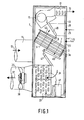
- a heat exchanger 3 is located centrally in an upright housing 1.
- This heat exchanger consists of a number of heat pipes 3 a, which are arranged in the housing 1 as a package in an inclined position. The warm ends of the heat pipes 3a are at the bottom and the cold ends are at the top. Through this heat exchanger 3, fresh air can flow from bottom to top in the direction of an arrow 5 and used air can flow from top to bottom in the direction of an arrow 7.
- the flow channels are divided by a partition.
- a supply air pipe flange 11 is attached to the housing 1.
- the supply air can flow into the pipe flange in the direction of an arrow 13, then flows in the direction of the arrow 5 to a blower 15 and leaves the device after flowing through a condenser 17 in the direction of an arrow 19 to the interior 21.
- This path is referred to as a fresh air duct.
- the used room air can enter the device 1 in the direction of two arrows 23 and 25 through inlet openings 27 and 29.
- the entry opening 27 into which the used room air enters in the direction of the arrow 23 is considered.
- This used room air flows downward in the direction of arrow 7, in the direction of arrow 31 through an evaporator 33 and through an outlet pipe 35 in the direction of arrow 37 to the outside.
- the pipeline in which the used exhaust air is heading in the direction the arrows 23, 7, 31 and 37 flows is referred to as the exhaust duct. While the blower 15 in the fresh air duct ensures that fresh air is pressed into the interior 21, a blower 39 sucks the used room air outside.
- the heat pump used consists of the compressor 41, the condenser 17 and the evaporator 33.
- a flap 43 in the fresh air duct and 45 in the exhaust air duct serve to guide the air within the device.
- the flap 43 As shown in FIG. 1, bears against the heat exchanger 3, it closes off the fresh air duct. If the flap 45 bears against the heat exchanger 3, this flap 45 closes off the exhaust air duct.
- the positions of the flaps 43 and 45 according to FIG. 1 represent the one end position of the flaps 43, 45.
- Shunt openings 47 and 49 are also provided between the fresh air and exhaust air ducts. These shunt openings can be closed with the flaps 43 and 45. If the flaps 43 and 45 lie against the shunt openings 47 and 49, the flaps have assumed their second end position.
- the shunt opening 49 is open, and the used room air can in the direction of arrow 25 through a pipe socket 51 directly via the blower 15 in the direction of arrow 19 after passing through the condenser 17 and receiving of heat from it can be reintroduced into the interior.
- Fig. 2 shows the position of the device in the position of FIG. 1.
- a pure heating operation with the help of the heat pump 17, 33, 41 takes place.
- the flaps 43 and 45 close the passage through the heat exchanger 3. This means that the blower 39 the fresh air sucked in in the direction of arrow 13 into the pipe flange in the direction of arrow 53 through the shunt opening 47 directly to the evaporator 33 and through the exhaust pipe 37 leads outside again. Only heat is extracted from this fresh air. Since the flap 43 also closes the heat exchanger 3, the room air drawn in via the pipe socket 51 flows through the blower 15 and the condenser 17 in the direction of an arrow 55 back into the interior. It is therefore a pure heating operation in which heat is extracted from the outside air and this extracted heat is used to heat the interior 21 by means of the heat pump.
- the flaps 43 and 45 have taken intermediate positions. In these intermediate positions, the shunt openings 47 and 49 are partially open, as is the heat exchanger 3. This means that, in addition to the flows in the direction of arrows 53 and 55 according to FIG. 2, flows 57 and 59 for ventilation operation are added for pure heating operation. So both the fresh and exhaust air ducts and the shunts are partially open.
- Fig. 4 shows the flaps 43 and 45 in a position in which they completely close the shunt openings 47 and 49.
- the air conveyed by the blowers 15 and 39 can only move in the direction of arrows 57 and 59 from the outside in and from the inside flow outwards.
- the room air extracted in the direction of arrow 59 is extracted from its heat. This heat is transferred to the fresh air flow 57 and is thus returned to the interior 21.
Landscapes
- Engineering & Computer Science (AREA)
- Chemical & Material Sciences (AREA)
- Combustion & Propulsion (AREA)
- Mechanical Engineering (AREA)
- General Engineering & Computer Science (AREA)
- Air-Conditioning Room Units, And Self-Contained Units In General (AREA)
- Central Air Conditioning (AREA)
- Cosmetics (AREA)
Abstract
Description
- Die Erfindung bezieht sich auf eine Vorrichtung zum Belüften und Heizen von Innenräumen, insbesondere Wohnräumen, mit von außen in den Innenraum und aus dem Innenraum nach außen führenden Frisch- und Abluftkanälen, in denen ein Luft/Luft-Wärmetauscher vorgesehen und die mit Gebläsen versehen sind, durch die Luft ein- und ausgeblasen wird, und mit einer Wärmepumpenvorrichtung mit einem Kondensator im Zuluftkanal und einem Verdampfer im Abluftkanal sowie einstellbaren Klappen, die auf einen reinen Luft/Luft-Wärmepumpenbetrieb ohne Luftaustausch von außen nach innen und umgekehrt oder einen Mischbetrieb aus Luftaustausch und Wärmepumpenbetrieb einstellbar sind, in dem sie vor und hinter dem Wärmeaustauscher über Nebenschlußöffnungen Nebenschlüsse und längs der Frisch- und Abluftkanäle den Durchlaß regeln.
- Eine derartige Vorrichtung ist aus der DE-OS 30 47 890 bekannt. Dort ist ein Frischluftkanal vorgesehen, der durch einen Wärmetauscher hindurch von der Außenseite zum Innenraum führt. Ein Gebläse sorgt für die Strömung in dem Frischluftkanal. Ein Abluftkanal erstreckt sich vom Innenraum durch den Wärmetauscher nach draußen, und ein Gebläse in ihm saugt verbrauchte Luft aus dem Innenraum ab. In dem Abluftkanal ist vor dem Auslaß ein Verdampfer angeordnet, und in dem Frischluftkanal befindet sich vor dem Einlaß in den Innenraum ein Kondensator. Verdampfer und Kondensator sind Teile einer Wärmepumpenanlage. Durch verschiedene Klappen ist es möglich, beiderseits des Wärmetauschers zwischen Frisch- und Abluftkanal Nebenschlüsse zu erzeugen, und weitere Klappen sorgen dafür, daß Frischluft- und Abluftkanal auch gesperrt werden können. Auf diese Weise läßt sich die Vorrichtung in verschiedenen Betriebszuständen betreiben. In einem Betriebszustand findet ein reiner Wärmeaustausch über den Wärmeaustauscher statt, wenn frische Luft angesaugt und verbrauchte Luft abgeblasen wird. Durch das Öffnen der Nebenschlüsse und Verschließen der Frisch- und Abluftkanäle kann ein reiner Wärmepumpenbetrieb erreicht werden, in dem die Außenluft nur durch den Verdampfer geführt wird und die Innenluft nur durch den Kondensator. Bei diesem Heizbetrieb wird der umgewälzten Außenluft Wärme entzogen, und die entzogene Wärme wird über den Kondensator der umgewälzten Innenluft zugegeben. Bei offenen Nebenschlußöffnungen und auch offenen Frisch- und Abluftkanälen ergibt sich eine Art Mischbetrieb mit Lüften und gleichzeitigem Heizen.
- Bei dieser bekannten Vorrichtung bereitet die Ansteuerung der verschiedenen Klappen große Schwierigkeiten. Der Steuerungsaufwand führt zu einem sehr komplizierten Steuermechanismus und einer unwirtschaftlichen Bauweise.
- Es ist Aufgabe der Erfindung, eine Vorrichtung der eingangs beschriebenen Art zu schaffen, bei der die Steuerung der verschiedenen Luftströmungen wesentlich vereinfacht ist.
- Die gestellte Aufgabe ist erfindungsgemäß dadurch gelöst, daß
- - nur je eine Klappe vor und eine Klappe hinter dem Wärmetauscher vorgesehen ist,
- - die Klappen in einer Endlage den Wärmetauscher und in der anderen Endlage die Nebenschlußöffnungen vollständig schließen,
- - die Klappen auf Zwischenstellungen einstellbar sind.
- Mit Hilfe von nur zwei Klappen läßt sich auf diese Weise der Lüftungsbetrieb, der Heizungsbetrieb und der kombinierte Lüftungs- und Heizungsbetrieb verwirklichen. Die Anordnung von nur zwei Klappen vereinfacht sowohl die Konstruktion der Vorrichtung als auch die Ansteuerung der Klappen.
- Nach einer weiteren Ausgestaltung der Erfindung ist vorgesehen, daß der Wärmetauscher ein Wärmerohraustauscher ist. Ein solcher Wärmerohraustauscher hat den großen Vorteil, daß er trotz kleiner Bauweise ohne sich bewegende Teile arbeitet. Auch dadurch wird eine Vereinfachung herbeigeführt bei kleiner Bauweise. In den Wärmerohren, deren warme Enden tiefer angeordnet sind als die kalten Enden, befindet sich eine verdampfbare Flüssigkeit, die durch die warme Abluft verdampft und durch die kalte Zuluft wieder kondensatiert. Durch die Hintereinanderschaltung von mehreren separaten Rohrreihen wird die Querleitung innerhalb der Wärmetauscherlänge unterbunden, so daß zusammen mit den Ausströmungsrichtungen der Luft ein optimaler Gegenstromwärmetauscher mit entsprechend gutem Wärmerückgewinnungsgrad entsteht.
- Die Erfindung wird anhand des in der Zeichnung dargestellten Ausführungsbeispieles näher erläutert.
- Es zeigen:
- Fig. 1 eine Seitenansicht der Vorrichtung mit Frischluft- und Ablauftkanal, Luft/Luft-Wärmepumpe und einem Wärmeaustauscher bei abgenommener Seitenwand,
- Fig. 2 bis 4 die Vorrichtung mit verschiedenen Klappenstellungen zur Erläuterung der verschiedenne Betriebsarten.
- In einem aufrechtstehenden Gehäuse 1 befindet sich zentral ein Wärmeaustauscher 3. Dieser Wärmetauscher besteht aus einer Anzahl von Wärmerohren 3a, die im Gehäuse 1 als Paket in Schräglage angeordnet sind. Die warmen Enden der Wärmerohre 3a liegen unten, und die kalten Enden liegen oben. Durch diesen Wärmeaustauscher 3 kann Frischluft in Richtung eines Pfeiles 5 von unten nach oben und verbrauchte Raumluft in Richtung eines Pfeiles 7 von oben nach unten durchströmen. Die Strömungskanäle sind geteilt mittels einer Trennwand. Außenseitig ist an das Gehäuse 1 ein Zuluftrohrflansch 11 angesetzt. Die Zuluft kann in Richtung eines Pfeiles 13 in den Rohrflansch einströmen, strömt dann in Richtung des Pfeiles 5 zu einem Gebläse 15 und verläßt die Vorrichtung nach dem Durchströmen eines Kondensators 17 in Richtung eines Pfeiles 19 zum Innenraum 21. Dieser Weg ist als Frischluftkanal bezeichnet.
- Die verbrauchte Raumluft kann in Richtung von zwei Pfeilen 23 und 25 durch Eintrittsöffnungen 27 und 29 in die Vorrichtung 1 eintreten. Betrachtet wird zunächst einmal die Eintrittsöffnung 27, in die die verbrauchte Raumluft in Richtung des Pfeiles 23 eintritt. Diese verbrauchte Raumluft strömt in Richtung des Pfeiles 7 nach unten, in Richtung eines Pfeiles 31 durch einen Verdampfer 33 und durch ein Auslaßrohr 35 in Richtung eines Pfeiles 37 nach außen weg. Der Leitungszug, in dem die verbrauchte Abluft in Richtung der Pfeile 23, 7, 31 und 37 strömt, wird als Abluftkanal bezeichnet. Während das Gebläse 15 im Frischluftkanal für das Eindrücken der Frischluft in den Innenraum 21 sorgt, saugt ein Gebläse 39 die verbrauchte Raumluft nach draußen ab.
- Die zum Einsatz kommende Wärmepumpe besteht aus dem Kompressor 41, dem Kondensator 17 und dem Verdampfer 33.
- Der Luftführung innerhalb der Vorrichtung dienen je eine Klappe 43 im Frischluftkanal und 45 im Abluftkanal. Wenn die Klappe 43, wie in Fig. 1 dargestellt ist, an dem Wärmetauscher 3 anliegt, dann schließt sie den Frischluftkanal ab. Liegt die Klappe 45 am Wärmetauscher 3 an, dann schließt diese Klappe 45 den Abluftkanal ab. Die Stellungen der Klappen 43 und 45 nach Fig. 1 stellen die eine Endlage der Klappen 43, 45 dar. Zwischen Frischluft- und Ablulftkanal sind noch Nebenschlußöffnungen 47 und 49 vorgesehen. Diese Nebenschlußöffnungen können mit Hilfe der Klappen 43 und 45 verschlossen werden. Liegen die Klappen 43 und 45 an den Nebenschlußöffnungen 47 und 49 an, dann haben die Klappen ihre zweite Endlage eingenommen.
- Hat die Klappe 43 die Lage nach Fig. 1, dann ist die Nebenschlußöffnung 49 geöffnet, und die verbrauchte Raumluft kann in Richtung des Pfeiles 25 durch einen Rohrstutzen 51 unmittelbar über das Gebläse 15 in Richtung des Pfeiles 19 nach dem Passieren des Kondensators 17 und Aufnahme von Wärme aus ihm wieder in den Innenraum eingeführt werden.
- Die einzelnen Betriebszustände werden nun anhand der Fig. 2 bis 4 im einzelnen erläutert.
- Fig. 2 zeigt die Stellung der Vorrichtung in der Stellung nach Fig. 1. in dieser Stellung findet ein reiner Heizbetrieb mit Hilfe der Wärmepumpe 17, 33, 41 statt. Die Klappen 43 und 45 verschließen den Durchlaß durch den Wärmetauscher 3. Das bedeutet, daß das Gebläse 39 die in Richtung des Pfeiles 13 in den Rohrflansch eingesaugte Frischluft in Richtung eines Pfeiles 53 durch die Nebenschlußöffnung 47 hindurch unmittelbar zum Verdampfer 33 und durch das Abluftrohr 37 wieder nach draußen abführt. Dieser angesaugten Frischluft wird also nur Wärme entzogen. Da die Klappe 43 ebenfalls den Wärmetauscher 3 verschließt, strömt die über den Rohrstutzen 51 eingesaugte Raumluft durch das Gebläse 15 und den Kondensator 17 in Richtung eines Pfeiles 55 wieder in den Innenraum zurück. Es handelt sich hier also um einen reinen Heizungsbetrieb, bei dem der Außenluft Wärme entzogen wird und diese entzogene Wärme mittels der Wärmepumpe zum Heizen des Innenraumes 21 ausgenutzt wird.
- In Fig. 3 haben die Klappen 43 und 45 Zwischenstellungen eingenommen. In diesen Zwischenstellungen sind die Nebenschlußöffnungen 47 und 49 teilweise geöffnet, ebenso wie der Wärmetauscher 3. Das bedeutet, daß zusätzlich zu den Strömungen in Richtung der Pfeile 53 und 55 nach Fig. 2 für reinen Heizbetrieb noch Strömungen 57 und 59 für Lüftungsbetrieb hinzutreten. Es sind also sowohl die Frisch- und Abluftkanäle als auch die Nebenschlüsse teilweise geöffnet.
- Fig. 4 zeigt die Klappen 43 und 45 in einer Stellung, in der sie die Nebenschlußöffnungen 47 und 49 vollständig verschließen. In diesem Fall kann die von den Gebläsen 15 und 39 geförderte Luft nur in Richtung der Pfeile 57 und 59 von außen nach innen und von innen nach außen strömen. Im Wärmetauscher wird der in Richtung des Pfeiles 59 abgesaugten Raumluft ihre Wärme entzogen. Diese Wärme wird an den Frischluftstrom 57 übergeben und damit wieder dem Innenraum 21 zugeführt.
- Für die drei Betriebsstellungen sind also nur zwei Klappen erforderlich, die mit Hilfe von Steuervorrichtungen erstellt werden. Die Steuerung dieser Klappen ist außerordentlich einfach zu verwirklichen.
Claims (3)
Applications Claiming Priority (2)
| Application Number | Priority Date | Filing Date | Title |
|---|---|---|---|
| DE19833315444 DE3315444A1 (de) | 1983-04-28 | 1983-04-28 | Vorrichtung zum belueften und heizen von innenraeumen, insbesondere wohnraeumen |
| DE3315444 | 1983-04-28 |
Publications (3)
| Publication Number | Publication Date |
|---|---|
| EP0127213A2 true EP0127213A2 (de) | 1984-12-05 |
| EP0127213A3 EP0127213A3 (en) | 1986-04-30 |
| EP0127213B1 EP0127213B1 (de) | 1989-07-12 |
Family
ID=6197607
Family Applications (1)
| Application Number | Title | Priority Date | Filing Date |
|---|---|---|---|
| EP84200564A Expired EP0127213B1 (de) | 1983-04-28 | 1984-04-19 | Vorrichtung zum Belüften und Heizen von Innenräumen, insbesondere Wohnräumen |
Country Status (5)
| Country | Link |
|---|---|
| US (1) | US4562955A (de) |
| EP (1) | EP0127213B1 (de) |
| JP (1) | JPS59208334A (de) |
| CA (1) | CA1227035A (de) |
| DE (2) | DE3315444A1 (de) |
Cited By (3)
| Publication number | Priority date | Publication date | Assignee | Title |
|---|---|---|---|---|
| DE3715520A1 (de) * | 1987-05-09 | 1988-12-01 | Dieter R Tiepoldt | Klimaanlage |
| EP0366642A3 (de) * | 1988-10-24 | 1991-04-03 | N.V. Mathias Systems | Vorrichtung zur energiesparenden Wärmerückgewinnung aus einem Fluid |
| DE4412844A1 (de) * | 1994-02-09 | 1995-08-10 | Stiebel Eltron Gmbh & Co Kg | Klimagerät |
Families Citing this family (47)
| Publication number | Priority date | Publication date | Assignee | Title |
|---|---|---|---|---|
| AT391933B (de) * | 1986-08-14 | 1990-12-27 | Altexa Lueftungstechnische Anl | Klima- und lueftungsgeraet zum einbau in eine wand, fenster oder dergleichen |
| DE3700944A1 (de) * | 1987-01-15 | 1988-07-28 | Erich Mosbacher | Einrichtung zur luftversorgung eines gebaeudeinnenraumes |
| DE3719392A1 (de) * | 1987-06-08 | 1988-12-29 | Hansa Ventilatoren Masch | Raumlufttechnisches geraet |
| JP2561749B2 (ja) * | 1990-10-11 | 1996-12-11 | 株式会社朝日工業社 | クリ−ンル−ムの空気循環方法 |
| DE19500527A1 (de) * | 1995-01-11 | 1996-07-18 | Kulmbacher Klimageraete | Klimagerät |
| US6385985B1 (en) * | 1996-12-04 | 2002-05-14 | Carrier Corporation | High latent circuit with heat recovery device |
| NO306797B1 (no) * | 1998-03-24 | 1999-12-20 | Sakki Liv | Multifunksjonelt luftkondisjoneringsanlegg, samt fremgangsmåte ved multifunksjonell kondisjonering av romluft |
| US6935409B1 (en) * | 1998-06-08 | 2005-08-30 | Thermotek, Inc. | Cooling apparatus having low profile extrusion |
| IT245248Y1 (it) * | 1998-07-30 | 2002-03-20 | Olimpia Splendid S P A | Condizionatore d'aria monoblocco ad installazione facilitata. |
| US6539736B1 (en) * | 1999-08-03 | 2003-04-01 | Mitsubishi Denki Kabushiki Kaisha | Method for controlling to cool a communication station |
| TW449654B (en) * | 1999-08-25 | 2001-08-11 | Fujitsu General Ltd | Air conditioner |
| DE19956038B4 (de) * | 1999-11-22 | 2007-04-12 | Pfannenberg Gmbh | Belüftungsvorrichtung für ein Gehäuse |
| FR2806786B1 (fr) * | 2000-03-23 | 2002-05-24 | Jacques Rollier | Appareil individuel monobloc reversible de climatisation du type air-air |
| KR100365401B1 (ko) * | 2000-09-30 | 2002-12-18 | 만도공조 주식회사 | 2차 열교환기능을 가진 열교환장치 |
| US6684653B2 (en) * | 2001-11-21 | 2004-02-03 | Nicholas H. Des Champs | Air-conditioner and air-to-air heat exchange for closed loop cooling |
| US9113577B2 (en) | 2001-11-27 | 2015-08-18 | Thermotek, Inc. | Method and system for automotive battery cooling |
| US7857037B2 (en) | 2001-11-27 | 2010-12-28 | Thermotek, Inc. | Geometrically reoriented low-profile phase plane heat pipes |
| JP2003289195A (ja) * | 2002-03-28 | 2003-10-10 | Mitsubishi Electric Corp | 冷却装置 |
| LU90926B1 (en) * | 2002-05-28 | 2003-12-01 | Uniflair Int Sa | Compact air-cooling device for a closed technical cabinet |
| KR100519309B1 (ko) * | 2003-06-03 | 2005-10-10 | 엘지전자 주식회사 | 신선공기 공급장치를 구비한 공조시스템 |
| US20050133204A1 (en) * | 2003-12-17 | 2005-06-23 | Renewaire, Llc | Energy recovery ventilator |
| CA2516002C (en) * | 2004-11-16 | 2013-05-28 | Jonathan G. Ritchey | Water condenser |
| TW200821512A (en) * | 2006-11-07 | 2008-05-16 | Jun-Guang Luo | Dual-phase transformation temperature control device and method |
| JP5095240B2 (ja) * | 2007-03-07 | 2012-12-12 | ハイアール グループ コーポレーション | 乾燥機 |
| EP2096369A1 (de) | 2008-02-29 | 2009-09-02 | Deerns Raadgevende Ingenieurs B.V. | Vorrichtung und Verfahren zur Kühlung eines Raums mit Rückführungsluft |
| DE102008043920A1 (de) * | 2008-11-20 | 2010-05-27 | BSH Bosch und Siemens Hausgeräte GmbH | Kondensationstrockner mit einer Wärmepumpe sowie Verfahren zu seinem Betrieb |
| ITBS20090080A1 (it) * | 2009-05-05 | 2010-11-06 | Simone Costanzo | Apparecchio per il trattamento dell'aria di un ambiente |
| KR20110088889A (ko) * | 2010-01-29 | 2011-08-04 | 주식회사 팬택 | 다중 모드 단말기의 전력 소모를 줄이기 위한 시스템 및 방법 |
| IT1398846B1 (it) * | 2010-02-17 | 2013-03-21 | Olimpia Splendid S P A | Condizionatore d'aria e metodo per il montaggio a parete dello stesso |
| US8408019B2 (en) * | 2010-12-07 | 2013-04-02 | Tai-Her Yang | Air conditioning device utilizing temperature differentiation of exhausted gas to even temperature of external heat exchanger |
| US9032742B2 (en) | 2010-12-30 | 2015-05-19 | Munters Corporation | Methods for removing heat from enclosed spaces with high internal heat generation |
| US9055696B2 (en) | 2010-12-30 | 2015-06-09 | Munters Corporation | Systems for removing heat from enclosed spaces with high internal heat generation |
| US9021821B2 (en) * | 2010-12-30 | 2015-05-05 | Munters Corporation | Ventilation device for use in systems and methods for removing heat from enclosed spaces with high internal heat generation |
| EP2493277A2 (de) * | 2011-02-22 | 2012-08-29 | Stulz-Chspl (India) PVT, Ltd. | Verbesserung im Kühlsystem für Telekommunikationsschutzvorrichtungen |
| WO2013116197A1 (en) | 2012-02-02 | 2013-08-08 | Carrier Corporation | Energy recovery ventilator and method of recovering energy |
| CN102889648A (zh) * | 2012-11-05 | 2013-01-23 | 马晓磊 | 双出风口空调 |
| CN103256842B (zh) * | 2013-05-15 | 2014-12-10 | 苏州惠林节能材料有限公司 | 一种热管式冷热回收器 |
| CN104729036A (zh) * | 2015-03-19 | 2015-06-24 | 合肥天鹅制冷科技有限公司 | 精确控温的冷凝热回收系统 |
| CN107218648A (zh) * | 2016-03-22 | 2017-09-29 | 上海东健净化有限公司 | 一种热管式新风处理机 |
| CN106678972B (zh) * | 2017-01-16 | 2020-04-24 | 广东美的制冷设备有限公司 | 一种换新风空调器 |
| CN106765847B (zh) * | 2017-01-16 | 2020-04-24 | 广东美的制冷设备有限公司 | 一种一体式换新风空调器 |
| CZ30909U1 (cs) * | 2017-02-14 | 2017-08-15 | Petr Morávek | Klimatizační vícezónová jednotka |
| EP3438561A1 (de) * | 2017-08-02 | 2019-02-06 | Kris Vanrenterghem | Luftbehandlungseinheit mit interner wärmepumpe |
| FR3084451A1 (fr) * | 2018-07-27 | 2020-01-31 | Muller Et Cie | Appareil monobloc de traitement climatique et de renouvellement d'air pour un local situe dans un batiment |
| US11460202B2 (en) | 2019-04-30 | 2022-10-04 | Gary Gerard Powers | Roof mounted ventilation assembly |
| CN113864882A (zh) * | 2021-05-20 | 2021-12-31 | 青岛海尔空调器有限总公司 | 壁挂式新风空调室内机及空调器 |
| CN115978767A (zh) * | 2023-02-03 | 2023-04-18 | 成都仙蓓五恒科技咨询服务有限公司 | 一种干式三冷源新风空调一体机的系统 |
Family Cites Families (8)
| Publication number | Priority date | Publication date | Assignee | Title |
|---|---|---|---|---|
| US3831395A (en) * | 1973-05-30 | 1974-08-27 | H Levy | Air conditioner |
| FR2288960A1 (fr) * | 1974-10-23 | 1976-05-21 | Carcuac Georges | Echangeur de chaleur |
| DE2844885A1 (de) * | 1978-10-14 | 1980-04-24 | Happel Kg | Wandluefter |
| EP0029573A3 (de) * | 1979-11-24 | 1981-12-16 | Uwe Klix | Wärmetauscher, deren Ausbildung und Anordnung in einer Einrichtung zur Wärmerückgewinnung durch Luftaustausch, insbesondere für Wohnhäuser und vergleichbare Anlagen |
| DE3027447A1 (de) * | 1980-07-19 | 1982-02-11 | Horst Joachim 6700 Ludwigshafen Schmittel | Vorrichtung zur be- und entlueftung |
| DE3047890A1 (de) * | 1980-12-19 | 1982-07-29 | Philips Patentverwaltung Gmbh, 2000 Hamburg | "vorrichtung zum belueften und heizen von innenraeumen" |
| JPS5837431A (ja) * | 1981-08-31 | 1983-03-04 | Matsushita Seiko Co Ltd | 壁貫通形ヒ−トポンプ式空気調和機 |
| JPS58173322A (ja) * | 1982-04-05 | 1983-10-12 | Matsushita Electric Ind Co Ltd | 空気調和機 |
-
1983
- 1983-04-28 DE DE19833315444 patent/DE3315444A1/de not_active Withdrawn
-
1984
- 1984-04-19 EP EP84200564A patent/EP0127213B1/de not_active Expired
- 1984-04-19 DE DE8484200564T patent/DE3478949D1/de not_active Expired
- 1984-04-25 JP JP59083592A patent/JPS59208334A/ja active Granted
- 1984-04-26 CA CA000452810A patent/CA1227035A/en not_active Expired
- 1984-04-26 US US06/604,088 patent/US4562955A/en not_active Expired - Fee Related
Cited By (4)
| Publication number | Priority date | Publication date | Assignee | Title |
|---|---|---|---|---|
| DE3715520A1 (de) * | 1987-05-09 | 1988-12-01 | Dieter R Tiepoldt | Klimaanlage |
| EP0366642A3 (de) * | 1988-10-24 | 1991-04-03 | N.V. Mathias Systems | Vorrichtung zur energiesparenden Wärmerückgewinnung aus einem Fluid |
| DE4412844A1 (de) * | 1994-02-09 | 1995-08-10 | Stiebel Eltron Gmbh & Co Kg | Klimagerät |
| DE4412844C2 (de) * | 1994-02-09 | 1999-06-17 | Stiebel Eltron Gmbh & Co Kg | Klimagerät |
Also Published As
| Publication number | Publication date |
|---|---|
| EP0127213B1 (de) | 1989-07-12 |
| DE3315444A1 (de) | 1984-10-31 |
| CA1227035A (en) | 1987-09-22 |
| EP0127213A3 (en) | 1986-04-30 |
| JPH0356373B2 (de) | 1991-08-28 |
| JPS59208334A (ja) | 1984-11-26 |
| DE3478949D1 (en) | 1989-08-17 |
| US4562955A (en) | 1986-01-07 |
Similar Documents
| Publication | Publication Date | Title |
|---|---|---|
| EP0127213B1 (de) | Vorrichtung zum Belüften und Heizen von Innenräumen, insbesondere Wohnräumen | |
| EP0055000B1 (de) | Vorrichtung zum Belüften und Heizen von Innenräumen | |
| DE1928939C3 (de) | Klimakammer | |
| DE3540729C2 (de) | ||
| DE4002560A1 (de) | Klimageraet | |
| EP0294730B1 (de) | Raumlufttechnisches Gerät | |
| DE3834440A1 (de) | Vorrichtung mit waermerueckgewinnung zur be- und entlueftung von raeumen mit waermeueberschuss | |
| DE2536297A1 (de) | Luftaufbereitungsventilator | |
| DE2700893C2 (de) | Kältemittelkreislauf für eine Wärmepumpe mit einem parallelepipedförmigen Gehäuse | |
| DE202004018206U1 (de) | Gerät zur Klimatisierung, wie Entfeuchter, Klimagerät, Lüftungsgerät u.dgl. | |
| DE1604240C3 (de) | Gerät zum Heizen und/oder Kühlen von Raumluft | |
| DE4431940A1 (de) | Frischluft-Klimaanlage | |
| EP2362153B1 (de) | Luftaustauschvorrichtung | |
| DE3341337A1 (de) | Klimageraet | |
| DE2020468B2 (de) | Luftseitig geregeltes Klimageraet fuer Vierleitersystem mit eingebautem Ventilator | |
| DE2447841C3 (de) | Klimagerät, insbesondere Luftentfeuchter | |
| DE102017202250A1 (de) | Klimagerät | |
| EP0109128B1 (de) | Wärmeaustauschende Belüftungsvorrichtung für Wohn- oder Arbeitsräume mit einem Lüfterrad | |
| DE19941780C2 (de) | Klimaanlage | |
| DE29806908U1 (de) | Gegenstand-Plattenwärmeübertrager | |
| DE102015118329B4 (de) | Verfahren zur Kühlung von Rechenzentren | |
| AT267139B (de) | Klimagerät | |
| DE19509166C1 (de) | In einem Luftkanal einer Klima- und/oder Belüftungsanlage angeordneter Sprühbefeuchter | |
| DE2756566C3 (de) | Lüftungsvorrichtung zur mechanischen Be- und Entlüftung | |
| EP2135495A1 (de) | Verfahren und vorrichtung zum abführen von wärme bei computerarbeitsplätzen |
Legal Events
| Date | Code | Title | Description |
|---|---|---|---|
| PUAI | Public reference made under article 153(3) epc to a published international application that has entered the european phase |
Free format text: ORIGINAL CODE: 0009012 |
|
| AK | Designated contracting states |
Designated state(s): DE FR GB IT SE |
|
| PUAL | Search report despatched |
Free format text: ORIGINAL CODE: 0009013 |
|
| AK | Designated contracting states |
Kind code of ref document: A3 Designated state(s): DE FR GB IT SE |
|
| RHK1 | Main classification (correction) |
Ipc: F24F 1/02 |
|
| 17P | Request for examination filed |
Effective date: 19861001 |
|
| 17Q | First examination report despatched |
Effective date: 19870311 |
|
| RAP1 | Party data changed (applicant data changed or rights of an application transferred) |
Owner name: N.V. PHILIPS' GLOEILAMPENFABRIEKEN Owner name: PHILIPS PATENTVERWALTUNG GMBH |
|
| GRAA | (expected) grant |
Free format text: ORIGINAL CODE: 0009210 |
|
| AK | Designated contracting states |
Kind code of ref document: B1 Designated state(s): DE FR GB IT SE |
|
| REF | Corresponds to: |
Ref document number: 3478949 Country of ref document: DE Date of ref document: 19890817 |
|
| ITF | It: translation for a ep patent filed | ||
| ET | Fr: translation filed | ||
| GBT | Gb: translation of ep patent filed (gb section 77(6)(a)/1977) | ||
| PLBE | No opposition filed within time limit |
Free format text: ORIGINAL CODE: 0009261 |
|
| STAA | Information on the status of an ep patent application or granted ep patent |
Free format text: STATUS: NO OPPOSITION FILED WITHIN TIME LIMIT |
|
| 26N | No opposition filed | ||
| ITTA | It: last paid annual fee | ||
| EAL | Se: european patent in force in sweden |
Ref document number: 84200564.7 |
|
| PGFP | Annual fee paid to national office [announced via postgrant information from national office to epo] |
Ref country code: GB Payment date: 19950331 Year of fee payment: 12 |
|
| ITPR | It: changes in ownership of a european patent |
Owner name: CAMBIO RAGIONE SOCIALE;PHILIPS ELECTRONICS N.V. |
|
| PGFP | Annual fee paid to national office [announced via postgrant information from national office to epo] |
Ref country code: FR Payment date: 19950420 Year of fee payment: 12 |
|
| PGFP | Annual fee paid to national office [announced via postgrant information from national office to epo] |
Ref country code: SE Payment date: 19950425 Year of fee payment: 12 |
|
| REG | Reference to a national code |
Ref country code: FR Ref legal event code: CD |
|
| PGFP | Annual fee paid to national office [announced via postgrant information from national office to epo] |
Ref country code: DE Payment date: 19950622 Year of fee payment: 12 |
|
| PG25 | Lapsed in a contracting state [announced via postgrant information from national office to epo] |
Ref country code: GB Effective date: 19960419 |
|
| PG25 | Lapsed in a contracting state [announced via postgrant information from national office to epo] |
Ref country code: SE Effective date: 19960420 |
|
| GBPC | Gb: european patent ceased through non-payment of renewal fee |
Effective date: 19960419 |
|
| PG25 | Lapsed in a contracting state [announced via postgrant information from national office to epo] |
Ref country code: FR Effective date: 19961227 |
|
| PG25 | Lapsed in a contracting state [announced via postgrant information from national office to epo] |
Ref country code: DE Effective date: 19970101 |
|
| EUG | Se: european patent has lapsed |
Ref document number: 84200564.7 |
|
| REG | Reference to a national code |
Ref country code: FR Ref legal event code: ST |