EP0127219A1 - Dispositif de réglage des aubes directrices d'une turbomachine axiale - Google Patents
Dispositif de réglage des aubes directrices d'une turbomachine axiale Download PDFInfo
- Publication number
- EP0127219A1 EP0127219A1 EP84200607A EP84200607A EP0127219A1 EP 0127219 A1 EP0127219 A1 EP 0127219A1 EP 84200607 A EP84200607 A EP 84200607A EP 84200607 A EP84200607 A EP 84200607A EP 0127219 A1 EP0127219 A1 EP 0127219A1
- Authority
- EP
- European Patent Office
- Prior art keywords
- adjusting
- fork
- sleeve
- adjusting sleeve
- axis
- Prior art date
- Legal status (The legal status is an assumption and is not a legal conclusion. Google has not performed a legal analysis and makes no representation as to the accuracy of the status listed.)
- Granted
Links
- 238000006073 displacement reaction Methods 0.000 claims description 6
- 239000007789 gas Substances 0.000 description 3
- 238000010276 construction Methods 0.000 description 2
- 239000000463 material Substances 0.000 description 1
- 230000004048 modification Effects 0.000 description 1
- 238000012986 modification Methods 0.000 description 1
- 230000001105 regulatory effect Effects 0.000 description 1
Images

Classifications
-
- F—MECHANICAL ENGINEERING; LIGHTING; HEATING; WEAPONS; BLASTING
- F01—MACHINES OR ENGINES IN GENERAL; ENGINE PLANTS IN GENERAL; STEAM ENGINES
- F01D—NON-POSITIVE DISPLACEMENT MACHINES OR ENGINES, e.g. STEAM TURBINES
- F01D17/00—Regulating or controlling by varying flow
- F01D17/10—Final actuators
- F01D17/12—Final actuators arranged in stator parts
- F01D17/14—Final actuators arranged in stator parts varying effective cross-sectional area of nozzles or guide conduits
- F01D17/16—Final actuators arranged in stator parts varying effective cross-sectional area of nozzles or guide conduits by means of nozzle vanes
- F01D17/162—Final actuators arranged in stator parts varying effective cross-sectional area of nozzles or guide conduits by means of nozzle vanes for axial flow, i.e. the vanes turning around axes which are essentially perpendicular to the rotor centre line
-
- F—MECHANICAL ENGINEERING; LIGHTING; HEATING; WEAPONS; BLASTING
- F01—MACHINES OR ENGINES IN GENERAL; ENGINE PLANTS IN GENERAL; STEAM ENGINES
- F01D—NON-POSITIVE DISPLACEMENT MACHINES OR ENGINES, e.g. STEAM TURBINES
- F01D17/00—Regulating or controlling by varying flow
- F01D17/20—Devices dealing with sensing elements or final actuators or transmitting means between them, e.g. power-assisted
-
- F—MECHANICAL ENGINEERING; LIGHTING; HEATING; WEAPONS; BLASTING
- F04—POSITIVE - DISPLACEMENT MACHINES FOR LIQUIDS; PUMPS FOR LIQUIDS OR ELASTIC FLUIDS
- F04D—NON-POSITIVE-DISPLACEMENT PUMPS
- F04D29/00—Details, component parts, or accessories
- F04D29/40—Casings; Connections of working fluid
- F04D29/52—Casings; Connections of working fluid for axial pumps
- F04D29/54—Fluid-guiding means, e.g. diffusers
- F04D29/56—Fluid-guiding means, e.g. diffusers adjustable
- F04D29/563—Fluid-guiding means, e.g. diffusers adjustable specially adapted for elastic fluid pumps
-
- Y—GENERAL TAGGING OF NEW TECHNOLOGICAL DEVELOPMENTS; GENERAL TAGGING OF CROSS-SECTIONAL TECHNOLOGIES SPANNING OVER SEVERAL SECTIONS OF THE IPC; TECHNICAL SUBJECTS COVERED BY FORMER USPC CROSS-REFERENCE ART COLLECTIONS [XRACs] AND DIGESTS
- Y10—TECHNICAL SUBJECTS COVERED BY FORMER USPC
- Y10T—TECHNICAL SUBJECTS COVERED BY FORMER US CLASSIFICATION
- Y10T74/00—Machine element or mechanism
- Y10T74/18—Mechanical movements
- Y10T74/18888—Reciprocating to or from oscillating
- Y10T74/1892—Lever and slide
- Y10T74/18936—Slidable connections
Definitions
- the invention relates to an adjusting device for the guide vanes of an axial turbomachine with an adjusting sleeve arranged in the interior of the machine housing, the displacement of which in the axial direction makes the guide vanes adjustable, the axial displacement of the adjusting sleeve being effected by means of an adjusting fork, the pivot axis of which in the machine housing and the arms thereof the adjustment sleeve are rotatably mounted.
- Such adjustment devices are known for example from CH 364 581 or DE-A 3 125 639 and are used for adjusting the guide vanes, for example of turbocompressors, expanders or gas turbines.
- a displacement of the adjusting sleeve in the axial direction causes the guide vanes to rotate about their axis.
- the support of the adjusting sleeve in the machine housing is difficult.
- the support of the adjusting sleeve by means of guide Stan described in DE 2235154 - are gen, wherein provided on one side two leksfix Schlierende rods and on the opposite side a horizontal sliding permitting supports, brings a particularly useful for relatively long adjustment sleeves solution.
- the invention sets itself the task of eliminating the disadvantages of the prior art and, in particular, of further developing and improving an adjusting device of the type mentioned at the outset in such a way that the adjusting sleeve support is avoided with a simple and inexpensive construction regardless of the length of the adjusting sleeve a sliding guide, has a considerably lower frictional resistance and self-locking is largely avoided.
- this object is achieved in that straps are arranged parallel to the arms of the adjustment fork, each with an axis of rotation provided in the machine housing and in the adjustment sleeve, the straps forming a parallelogram guide for the adjustment sleeve with respect to the machine housing with the arms of the adjustment fork.
- This parallelogram guide ensures an extremely exact translatory movement of the adjusting sleeve achieved with the lowest possible friction, whereby tilting of the adjusting sleeve is largely avoided and self-locking is prevented.
- the points of application of the adjusting force that is to say the pivot points of the adjusting fork arms and the tabs in the adjusting sleeve, are provided at the height of the axis and the tilting moment is thus kept as small as possible.
- the adjustment fork has sufficient rigidity, as described, for example, in DE-A 3 125 639.
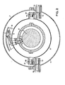
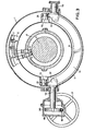
- a rotor 2 is arranged centrally in a housing 1 of an axial compressor and is provided with rotor blades 3 on its outside.
- the rotor 2 is concentrically surrounded by a fixed guide vane carrier 4, in which adjustable guide vanes 5, that is to say rotatable about an adjustment axis, and further fixed guide vanes 5 1 are used.
- the guide vanes 5 of the outer guide vane ring are provided with adjusting levers 6 which engage in annular grooves 7 of an axially displaceable adjusting sleeve 8.
- this adjusting sleeve 8 is displaced in the axial direction, the adjusting levers 6 are pivoted and the guide vanes 5 are accordingly rotated about their axis.
- the other guide vanes 5 1 can either be fixed or adjustable in a manner analogous to that of the guide vanes 5.
- the necessary axial displacement of the adjusting sleeve 8 takes place by means of a pivotable adjusting fork 11 which is rotatable about pivot axes 10 and is mounted in the housing 1.
- the arms 12 of this adjusting fork engage in pivot points 13 in the adjusting sleeve 8, so that when the adjusting fork 11 is pivoted about an angle c4 shifts the adjusting sleeve 8 by a path S in the axial direction.
- the axis of rotation 13 of the adjustment fork arms is selected such that it lies approximately at the level of the axis A of the turbomachine, so that the adjustment force acts in the center of the adjustment cylinder and a tilting moment is avoided as far as possible.
- brackets 14 are provided which are rotatably mounted in the machine housing 1 on both sides in the pivot points of an axis of rotation 15.
- the tabs 14 have at their other end on both sides further pivots 16 which engage in the adjusting sleeve 8.
- the distances between the axes of rotation 10 and 13 and 15 and 16 on the one hand, and the axes of rotation 13 and 16 and 10 and 15 on the other hand, are chosen to be as exactly as possible, so that a parallelogram guide that is as precise as possible is formed, which ensures precise guidance of the adjusting sleeve 8 in the axial direction, with a particularly simple and inexpensive construction and the lowest possible frictional forces.
- the axis of rotation 16 of the brackets has approximately the same distance from the axis A as the axis of rotation 13 of the adjustment fork, or if both axes of rotation 13 and 16 are selected at axis height.
- the parallelogram long sides 13 - 16 and 10 - 15 run parallel to the axis A.
- a solution with an oblique parallelogram is also possible, in which the axes of rotation 13 and 16 or 10 and 15 have a different axis spacing, the parallelogram long sides 13 - 16 and 10 - 15 run diagonally to the axis A.
- the other fulcrums 16 and 13 of the adjusting cylinder 8 describe a piece of a circular arc, only the axial component being used for adjusting the guide vanes.
- the vertical component to the axis which is only relatively small in the usual adjustment paths, can be accommodated in the annular grooves 7 without difficulty by a sufficient radial play of the sliding blocks of the adjusting lever 6.
- the drive for the adjustment fork 11 can be carried out manually or by a motor via a control or regulating device and can engage the adjustment fork 11 at a suitable point.
- a handwheel 17 is provided for this purpose, which acts via a worm 18 in a gearbox 19 on a toothed ring 20, which is seated firmly on the extended end of the one pivot axis 10.
- the drive can also take place in a different way and act on the adjusting fork 11 at a different point.
- connection points of the adjustment fork with the machine housing can also be provided at the outer end of the arms of the adjustment fork instead of between the apex of the adjustment fork and the connection points with the adjustment sleeve.
- the outer ends of the adjustment fork can also be connected to one another to improve stability and rigidity, so that the fork becomes a continuous ring.
- the tabs can also be connected at their ends and thus also form a fork or a ring.
- other adjustment devices can also be provided which work with a sleeve of any shape which can be displaced in the axial direction.
- the fork can be adjusted instead of at the pivot points, for example also on an extension specified at the apex of the fork by means of a linearly acting servomotor.
Landscapes
- Engineering & Computer Science (AREA)
- Mechanical Engineering (AREA)
- General Engineering & Computer Science (AREA)
- Structures Of Non-Positive Displacement Pumps (AREA)
- Control Of Turbines (AREA)
- Supercharger (AREA)
Priority Applications (1)
| Application Number | Priority Date | Filing Date | Title |
|---|---|---|---|
| AT84200607T ATE21435T1 (de) | 1983-05-31 | 1984-05-02 | Verstelleinrichtung fuer die leitschaufeln einer axialen turbomaschine. |
Applications Claiming Priority (2)
| Application Number | Priority Date | Filing Date | Title |
|---|---|---|---|
| CH2972/83 | 1983-05-31 | ||
| CH2972/83A CH661772A5 (de) | 1983-05-31 | 1983-05-31 | Axiale turbomaschine. |
Publications (2)
| Publication Number | Publication Date |
|---|---|
| EP0127219A1 true EP0127219A1 (fr) | 1984-12-05 |
| EP0127219B1 EP0127219B1 (fr) | 1986-08-13 |
Family
ID=4245770
Family Applications (1)
| Application Number | Title | Priority Date | Filing Date |
|---|---|---|---|
| EP84200607A Expired EP0127219B1 (fr) | 1983-05-31 | 1984-05-02 | Dispositif de réglage des aubes directrices d'une turbomachine axiale |
Country Status (6)
| Country | Link |
|---|---|
| US (1) | US4558986A (fr) |
| EP (1) | EP0127219B1 (fr) |
| JP (1) | JPS59231106A (fr) |
| AT (1) | ATE21435T1 (fr) |
| CH (1) | CH661772A5 (fr) |
| DE (2) | DE3322192C1 (fr) |
Cited By (1)
| Publication number | Priority date | Publication date | Assignee | Title |
|---|---|---|---|---|
| EP1031703A3 (fr) * | 1999-02-23 | 2000-09-13 | ROLLS-ROYCE plc | Dispositifs de commande d'aubes directrices |
Families Citing this family (7)
| Publication number | Priority date | Publication date | Assignee | Title |
|---|---|---|---|---|
| US4925364A (en) * | 1988-12-21 | 1990-05-15 | United Technologies Corporation | Adjustable spacer |
| US4990056A (en) * | 1989-11-16 | 1991-02-05 | General Motors Corporation | Stator vane stage in axial flow compressor |
| FR2920469A1 (fr) * | 2007-08-30 | 2009-03-06 | Snecma Sa | Aube a calage variable de turbomachine |
| US20100172743A1 (en) * | 2009-01-06 | 2010-07-08 | General Electric Company | Variable position guide vane actuation system and method |
| US8297918B2 (en) * | 2009-01-06 | 2012-10-30 | General Electric Company | Variable position guide vane actuation system and method |
| GB201409449D0 (en) | 2014-05-28 | 2014-07-09 | Rolls Royce Deutschland | A variable stator vane arrangment |
| DE112015003201B4 (de) * | 2014-07-10 | 2025-03-13 | Mitsubishi Heavy Industries, Ltd. | Wartungsverfahren für variable leitflügelvorrichtung und variable leitflügelvorrichtung |
Citations (6)
| Publication number | Priority date | Publication date | Assignee | Title |
|---|---|---|---|---|
| DE903052C (de) * | 1941-12-28 | 1954-02-01 | Maschf Augsburg Nuernberg Ag | Abgasturbogeblaese fuer Brennkraftmaschinen, insbesondere Zweitakttbrennkraftmaschinen |
| DE1121885B (de) * | 1960-06-14 | 1962-01-11 | Daimler Benz Ag | Leitschaufel-Verstellvorrichtung fuer Stroemungsmaschinen, insbesondere Gasturbinen |
| CH364581A (de) * | 1959-02-13 | 1962-09-30 | Sulzer Ag | Axialverdichter mit drehbaren Leitschaufeln |
| GB911535A (en) * | 1959-08-24 | 1962-11-28 | Rolls Royce | Compressors for gas turbine engines |
| US4214850A (en) * | 1977-10-12 | 1980-07-29 | Ishikawajima-Harima Jukogyo Kabushiki Kaisha | Variable-capacity radial turbine |
| FR2508564A1 (fr) * | 1981-06-26 | 1982-12-31 | Sulzer Ag | Dispositif de reglage des aubes directrices d'une turbomachine axiale |
Family Cites Families (3)
| Publication number | Priority date | Publication date | Assignee | Title |
|---|---|---|---|---|
| US2575665A (en) * | 1943-11-13 | 1951-11-20 | Borg Warner | Clutch control for marine transmission |
| DE1583675C3 (de) * | 1967-12-28 | 1973-01-04 | Mannesmann-Meer Ag, 4050 Moenchengladbach | Axiale Kokillenbewegungseinrichtung für Stranggießanlagen |
| CH553922A (de) * | 1972-07-13 | 1974-09-13 | Bbc Sulzer Turbomaschinen | Abstuetzvorrichtung fuer eine verstellhuelse. |
-
1983
- 1983-05-31 CH CH2972/83A patent/CH661772A5/de not_active IP Right Cessation
- 1983-06-21 DE DE3322192A patent/DE3322192C1/de not_active Expired
-
1984
- 1984-05-02 EP EP84200607A patent/EP0127219B1/fr not_active Expired
- 1984-05-02 DE DE8484200607T patent/DE3460468D1/de not_active Expired
- 1984-05-02 AT AT84200607T patent/ATE21435T1/de not_active IP Right Cessation
- 1984-05-07 US US06/608,075 patent/US4558986A/en not_active Expired - Fee Related
- 1984-05-31 JP JP59109801A patent/JPS59231106A/ja active Granted
Patent Citations (6)
| Publication number | Priority date | Publication date | Assignee | Title |
|---|---|---|---|---|
| DE903052C (de) * | 1941-12-28 | 1954-02-01 | Maschf Augsburg Nuernberg Ag | Abgasturbogeblaese fuer Brennkraftmaschinen, insbesondere Zweitakttbrennkraftmaschinen |
| CH364581A (de) * | 1959-02-13 | 1962-09-30 | Sulzer Ag | Axialverdichter mit drehbaren Leitschaufeln |
| GB911535A (en) * | 1959-08-24 | 1962-11-28 | Rolls Royce | Compressors for gas turbine engines |
| DE1121885B (de) * | 1960-06-14 | 1962-01-11 | Daimler Benz Ag | Leitschaufel-Verstellvorrichtung fuer Stroemungsmaschinen, insbesondere Gasturbinen |
| US4214850A (en) * | 1977-10-12 | 1980-07-29 | Ishikawajima-Harima Jukogyo Kabushiki Kaisha | Variable-capacity radial turbine |
| FR2508564A1 (fr) * | 1981-06-26 | 1982-12-31 | Sulzer Ag | Dispositif de reglage des aubes directrices d'une turbomachine axiale |
Cited By (1)
| Publication number | Priority date | Publication date | Assignee | Title |
|---|---|---|---|---|
| EP1031703A3 (fr) * | 1999-02-23 | 2000-09-13 | ROLLS-ROYCE plc | Dispositifs de commande d'aubes directrices |
Also Published As
| Publication number | Publication date |
|---|---|
| ATE21435T1 (de) | 1986-08-15 |
| DE3322192C1 (de) | 1984-07-12 |
| JPS59231106A (ja) | 1984-12-25 |
| EP0127219B1 (fr) | 1986-08-13 |
| JPH0312201B2 (fr) | 1991-02-19 |
| US4558986A (en) | 1985-12-17 |
| CH661772A5 (de) | 1987-08-14 |
| DE3460468D1 (en) | 1986-09-18 |
Similar Documents
| Publication | Publication Date | Title |
|---|---|---|
| DE3829022C2 (fr) | ||
| DE7523106U (de) | Gehaeuseabstuetzung fuer im betrieb sich dehnende, horizontalachsige gehaeuse, insbesondere fuer turbomaschinengehaeuse | |
| DE2806463C2 (de) | Einrichtung zum axialen Einstellen einer in einer Öffnung eines Ventilgehäuses angeordneten, ein Ende einer Schwenkwelle eines drehbaren Ventilschließgliedes aufnehmenden Lagerbüchse | |
| DE69601695T2 (de) | Innenlager einer schwenkbaren Schaufel | |
| DE7523183U (de) | Einstellvorrichtung fuer koaxiale maschinenteile | |
| DE3145689C2 (fr) | ||
| EP0202399B1 (fr) | Support d'appareil d'observation optique | |
| DE2453558C3 (de) | Schubgas-Umlenkschaufel | |
| EP0127219B1 (fr) | Dispositif de réglage des aubes directrices d'une turbomachine axiale | |
| DE3320699A1 (de) | Vorrichtung zum veraendern des leitschaufelwinkels bei axialen stroemungsmaschinen | |
| CH677202A5 (fr) | ||
| EP0056171A1 (fr) | Dispositif de fixation pour un carter de turbine | |
| DE2220468C3 (de) | Einrichtung zum Ausgleich des bei Verstellpropellern auf die Propellerblätter wirkenden Zentrifugaldrehmoments | |
| EP0808992A2 (fr) | Valve à manchon rotatif pour le contrÔle du débit de vapeur d'une turbine à vapeur | |
| EP0011681A1 (fr) | Baromètre | |
| DE2033704A1 (de) | Dampfungseinrichtung | |
| DE102018103441B4 (de) | Haltefutter für Maschinen zur Herstellung von Glasbehältnissen | |
| DE10217570B4 (de) | In Schnittrichtung beweglicher Besäumtisch und Holzbearbeitungsmaschine mit einem Besäumtisch | |
| AT367872B (de) | Verstelleinrichtung fuer die leitschaufeln eines axialverdichters | |
| DE20007283U1 (de) | Rotorkopf für einen Modellhubschrauber mit vertikal verschiebbarer Paddelstange | |
| DE3125639A1 (de) | "verstelleinrichtung fuer die leitschaufeln einer axialturbomaschine" | |
| DE2951832C2 (de) | Antrieb zum Schwenken und Axialverschieben eines mit einem Widerstandsschweißwerkzeug versehenen Auslegers | |
| DE2711409A1 (de) | Schaufelkranz einer hydraulischen maschine mit festen schaufeln | |
| DE643839C (de) | Schiefscheibengetriebe fuer Kolbenmaschinen, insbesondere Brennkraftmaschinen | |
| DE707401C (de) | Elastisches Zwischenstueck an einer ausschiebbaren Spreizklappe |
Legal Events
| Date | Code | Title | Description |
|---|---|---|---|
| PUAI | Public reference made under article 153(3) epc to a published international application that has entered the european phase |
Free format text: ORIGINAL CODE: 0009012 |
|
| 17P | Request for examination filed |
Effective date: 19840502 |
|
| AK | Designated contracting states |
Designated state(s): AT DE FR GB IT NL |
|
| GRAA | (expected) grant |
Free format text: ORIGINAL CODE: 0009210 |
|
| AK | Designated contracting states |
Kind code of ref document: B1 Designated state(s): AT DE FR GB IT NL |
|
| REF | Corresponds to: |
Ref document number: 21435 Country of ref document: AT Date of ref document: 19860815 Kind code of ref document: T |
|
| REF | Corresponds to: |
Ref document number: 3460468 Country of ref document: DE Date of ref document: 19860918 |
|
| ITF | It: translation for a ep patent filed | ||
| ET | Fr: translation filed | ||
| PLBE | No opposition filed within time limit |
Free format text: ORIGINAL CODE: 0009261 |
|
| STAA | Information on the status of an ep patent application or granted ep patent |
Free format text: STATUS: NO OPPOSITION FILED WITHIN TIME LIMIT |
|
| 26N | No opposition filed | ||
| ITTA | It: last paid annual fee | ||
| PGFP | Annual fee paid to national office [announced via postgrant information from national office to epo] |
Ref country code: DE Payment date: 19950418 Year of fee payment: 12 |
|
| PGFP | Annual fee paid to national office [announced via postgrant information from national office to epo] |
Ref country code: GB Payment date: 19950419 Year of fee payment: 12 |
|
| PGFP | Annual fee paid to national office [announced via postgrant information from national office to epo] |
Ref country code: FR Payment date: 19950420 Year of fee payment: 12 |
|
| PGFP | Annual fee paid to national office [announced via postgrant information from national office to epo] |
Ref country code: AT Payment date: 19950426 Year of fee payment: 12 |
|
| PGFP | Annual fee paid to national office [announced via postgrant information from national office to epo] |
Ref country code: NL Payment date: 19950531 Year of fee payment: 12 |
|
| PG25 | Lapsed in a contracting state [announced via postgrant information from national office to epo] |
Ref country code: GB Effective date: 19960502 Ref country code: AT Effective date: 19960502 |
|
| PG25 | Lapsed in a contracting state [announced via postgrant information from national office to epo] |
Ref country code: NL Effective date: 19961201 |
|
| GBPC | Gb: european patent ceased through non-payment of renewal fee |
Effective date: 19960502 |
|
| PG25 | Lapsed in a contracting state [announced via postgrant information from national office to epo] |
Ref country code: FR Effective date: 19970131 |
|
| PG25 | Lapsed in a contracting state [announced via postgrant information from national office to epo] |
Ref country code: DE Effective date: 19970201 |
|
| NLV4 | Nl: lapsed or anulled due to non-payment of the annual fee |
Effective date: 19961201 |
|
| REG | Reference to a national code |
Ref country code: FR Ref legal event code: ST |