EP0127251A2 - Soupape pour fluide - Google Patents
Soupape pour fluide Download PDFInfo
- Publication number
- EP0127251A2 EP0127251A2 EP84300879A EP84300879A EP0127251A2 EP 0127251 A2 EP0127251 A2 EP 0127251A2 EP 84300879 A EP84300879 A EP 84300879A EP 84300879 A EP84300879 A EP 84300879A EP 0127251 A2 EP0127251 A2 EP 0127251A2
- Authority
- EP
- European Patent Office
- Prior art keywords
- valve
- chamber
- passage
- control
- flexible wall
- Prior art date
- Legal status (The legal status is an assumption and is not a legal conclusion. Google has not performed a legal analysis and makes no representation as to the accuracy of the status listed.)
- Ceased
Links
Images

Classifications
-
- F—MECHANICAL ENGINEERING; LIGHTING; HEATING; WEAPONS; BLASTING
- F02—COMBUSTION ENGINES; HOT-GAS OR COMBUSTION-PRODUCT ENGINE PLANTS
- F02M—SUPPLYING COMBUSTION ENGINES IN GENERAL WITH COMBUSTIBLE MIXTURES OR CONSTITUENTS THEREOF
- F02M9/00—Carburettors having air or fuel-air mixture passage throttling valves other than of butterfly type; Carburettors having fuel-air mixing chambers of variable shape or position
- F02M9/10—Carburettors having air or fuel-air mixture passage throttling valves other than of butterfly type; Carburettors having fuel-air mixing chambers of variable shape or position having valves, or like controls, of elastic-wall type for controlling the passage, or for varying cross-sectional area, of fuel-air mixing chambers or of the entry passage
- F02M9/106—Pneumatic or hydraulic control
-
- F—MECHANICAL ENGINEERING; LIGHTING; HEATING; WEAPONS; BLASTING
- F02—COMBUSTION ENGINES; HOT-GAS OR COMBUSTION-PRODUCT ENGINE PLANTS
- F02D—CONTROLLING COMBUSTION ENGINES
- F02D9/00—Controlling engines by throttling air or fuel-and-air induction conduits or exhaust conduits
- F02D9/08—Throttle valves specially adapted therefor; Arrangements of such valves in conduits
- F02D9/18—Throttle valves specially adapted therefor; Arrangements of such valves in conduits having elastic-wall valve members
-
- Y—GENERAL TAGGING OF NEW TECHNOLOGICAL DEVELOPMENTS; GENERAL TAGGING OF CROSS-SECTIONAL TECHNOLOGIES SPANNING OVER SEVERAL SECTIONS OF THE IPC; TECHNICAL SUBJECTS COVERED BY FORMER USPC CROSS-REFERENCE ART COLLECTIONS [XRACs] AND DIGESTS
- Y10—TECHNICAL SUBJECTS COVERED BY FORMER USPC
- Y10S—TECHNICAL SUBJECTS COVERED BY FORMER USPC CROSS-REFERENCE ART COLLECTIONS [XRACs] AND DIGESTS
- Y10S261/00—Gas and liquid contact apparatus
- Y10S261/56—Variable venturi
Definitions
- the present invention relates to a valve for fluids, more particularly, for air or fuel/air mixtures in combustion engines.
- the conventional throttle valve such as is found in a vehicle carburettor, employs a "butterfly" plate cooperating with a valve seat to vary the dimensions of a through-passage as the throttle plate turns relative to, the valve seat.
- a butterfly valve One disadvantage of a butterfly valve is that the control of throughput is not accurate enough to ensure the most economic use of fuel. Another disadvantage is that it is difficult to control the opening of a butterfly valve, and therefore the air flow through the valve, in response to an electrical signal from an electronic engine management system
- the present invention seeks to provide a valve which may be used as a throttle valve in an internal combustion engine, to afford greater control over the air intake than can be achieved by means of a butterfly valve.
- a throttle valve for use in a motor vehicle in which a fluid flow path having a core positioned .centrally therein is defined by a tube having a flexible wall which separates the flow path from an adjacent working fluid chamber, whereby changes in the pressure within the chamber cause deformation of the flexible wall resulting in changes in the tube cross-section between a wide open throttle position and a valve closed position, characterised in that the flexible wall takes up a valve closed position when the pressures on opposite sides of the wall are equal.
- a flexible-walled tube as a valve to control the flow of a fluid, it is possible to control the throughput with greater accuracy.
- the through passage of the tube is not constricted by an asymmetrical valve closure member, such as the butterfly valve of a conventional carburettor, and may therefore operate with an increased through flow for a given internal cross-section, and with reduced turbulence under given flow conditions.
- a throttle valve In a motor vehicle engine, a throttle valve is provided to throttle the intake of air or of an air/fuel mixture into the engine. During normal operation, although the throttle valve is closed, this intake is not normally shut off completely, although under some engine management proposals it may possibly be desirable to shut off the intake completely. When the engine is idling, air is still normally reaching the engine through an idle passage. This idle passage may be through the valve, or may be external of the valve. References in this specification to a "valve closed” position should therefore be read accordingly, i.e. in the "valve closed” position, the valve may still provide for an idle passage through the valve.
- the core may have a through passage which remains open when the flexible wall seals against the core, to define a minimum fluid flow or idle passge, from one side of the valve to the other.
- minimum fluid flow may be provided through an external passage which extends from one side of the valve to the other.
- the external passage may communicate with the working fluid chamber so that the chamber can be connected to the fluid pressure on either side of the valve, and the passage may include a control valve for controlling flow through the passage.
- the control valve may be positioned in the external passage between the chamber and the downstream end of the through flow passage.
- the first control valve can be normally open, and the second control valve can be normally closed.
- closure control means are provided, for controlling the movement of the flexible wall in a valve closing direction, the control means being adapted to limit the wall movement at a predetermined position before the wall seals against the valve core, so that a minimum fluid flow is possible from one side of the valve to the other, between the core and the flexible wall.
- control means it would be possible for the control means to be overridden to close the valve completely.
- An external passage may extend from one side of the valve to the other to communicate with the working fluid chamber, and a change-over control valve may be provided at the point where the external passage communicates with the chamber, the control valve having a first position where it allows communication between the chamber and the downstream side of the valve and a second position where it allows communication between the chamber and the upstream side of the valve.
- the change-over control valve can be biassed into its second position.
- the invention also provides an internal combustion engine having a throttle valve for controlling the air intake, the valve being as set forth above, and the upstream side of the valve being connected to an air intake through an air filter and the downstream side being connected to the engine intake manifold vacuum.
- the working fluid chamber may be connected to engine manifold vacuum.
- the valve 1 shown in Figure 1 comprises an inlet pipe 10 and an outlet pipe 12 fitting in a fluid tight manner in a housing 20.
- a flexible tube 14 is joined by means of seals 16 and 18 in a fluid tight manner, to the pipes 10 and 12 respectively.
- the flexible tube divides the housing interior into a fluid through flow passage 25 and a surrounding working fluid chamber 23 having a control port 22.
- a narrow tube 24 passes centrally down the through flow passage 25 from an upstream end 27 to a downstream end 29 and provides a by-pass line to supply a small amount of air such as is required for engine idling.
- the hydraulic or pneumatic pressure within the chamber 23 is changed by admission or removal of a working fluid through the port 22.
- This causes a deformation of the flexible walled tube 14 between limit positions 14a and 14b, shown in dotted lines.
- the internal through flow cross-section of the passage 25 changes, enabling control of the fluid flow indicated by arrows 26.
- the flexible tube 14 in its rest condition adopts the position 14b and is deformed to open the passage 25 by removal of the working fluid from the control chamber.
- the return to the rest position may rely exclusively on the elasticity of the tube 14, or it may be assisted by admission of the working fluid under positive pressure.
- the tube 14 is an elastic tube which, when relaxed, has a constant cross-section of dimension substantially equal to its centre part in the position 14b. To fit the tube, its ends are stretched to fit over the inlet and outlet pipes 10 and 12.
- valve fails "safe", i.e. if the working fluid supply or he electrical control signal is interrupted, the valve will automatically close, and stop fuel flow.
- Suitable materials for the tube 14 are elastomers such as neoprene, nitrile rubber, fluoro-silicone and epichlorohydrin.
- the valve 30 shown in Figure 2 is similar to that shown in Figure 1, but includes a solid body or core 32 mounted concentrically in the through flow passage 25. This body is supported by retaining wires 34.
- the body 3 2 may have a double cone shape as shown and helps to provide a good seal when the tube 14 extends inwardly.
- the body will be shaped in accordance with aerodynamic considerations to provide a low resistance to flow, and to this end the vertices of the body shown in the drawing may all be rounded.
- the greatest diameter of the body should be just sufficient to provide a good seal when the tube extends inwardly.
- pneumatic force is used, derived from the vehicle manifold vacuum.
- the rest position of the flexible tube 14 is shown in Figure 2 where the valve is closed.
- a negative pressure is applied to the chamber 36. This negative pressure is derived from the vacuum created by the engine on the manifold side 38 of the valve.
- a normally open control valve 40 is closed and a normally closed control valve 42 is opened.
- the negative pressure in chamber 36 has to be released. This is done by closing the control valve 42 and opening the control valve 40. The pressure in the chamber 36 can then reach equilibrium with the pressure on the air filter side 44 of the valve.
- control valves 40 and 42 can be operated by electrical solenoids which can be controlled by electronic logic or can be incorporated in an electronic engine control system or in a cruise control system.
- the flow required to support idling can take place through the pneumatic circuit 46, whilst the tube 14 closes the valve.
- the normally open control valve 40 will remain unoperated and thus open.
- the flow through the circuit 46 will thus be entirely through the control valve 42, the opening of which can be accurately controlled.
- the control valve 40 (and the control valve 42, if used) can be a simple ON/OFF pulse width modulated or proportional solenoid valve.
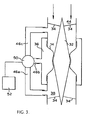
- both the control valves 40 and 42 are replaced by a single change-over control valve 50 arranged at the junction of the pneumatic circuit channels 46a, 46b and 46c.
- This control valve 50 can be operated to connect the manifold side 38 of the valve to the chamber 36, via channels 46a and 46b, or to connect the air filter side 44 of the valve to the chamber 36, via channels 46b and 46c.
- the pressure in the chamber 36 can be controlled by either connecting the chamber to manifold vacuum through passages 46a and 46b, or by connecting the chamber to ambient pressure through passages 46b and 46c.
- control valve To control this pressure accurately, the position of the control valve must be carefully modulated. This can be done by means of a solenoid control 52.
- the passages 46a and 46c are not used as a bypass. Instead, the valve operation is accurately controlled by controlling the pressure in the chamber 36 so that an end or "valve closed" position is reached before the flexible wall 14 seals against the core 32. A minimum through flow for engine idling purposes is then established between the core and the flexible wall.
- control circuitry for the solenoid control 52 can be arranged so as to permit this.
- a valve as described can be easily incorporated in a microprocessor controlled engine system, with the solenoid valve or valves being electronically controlled, in contrast with the cable-operated butterfly valves currently in use.
- valve is cheap to construct and can withstand under-bonnet conditions. Because the valve is cheap and simple, one of the valves could be provided for each cylinder of an engine, and individual control of the valves could lead to improved fuel economy.
Landscapes
- Engineering & Computer Science (AREA)
- Chemical & Material Sciences (AREA)
- Combustion & Propulsion (AREA)
- Mechanical Engineering (AREA)
- General Engineering & Computer Science (AREA)
- Control Of Throttle Valves Provided In The Intake System Or In The Exhaust System (AREA)
- Check Valves (AREA)
Applications Claiming Priority (2)
| Application Number | Priority Date | Filing Date | Title |
|---|---|---|---|
| GB8314988 | 1983-05-31 | ||
| GB08314988A GB2140895A (en) | 1983-05-31 | 1983-05-31 | Fluid valve |
Publications (2)
| Publication Number | Publication Date |
|---|---|
| EP0127251A2 true EP0127251A2 (fr) | 1984-12-05 |
| EP0127251A3 EP0127251A3 (fr) | 1985-09-18 |
Family
ID=10543622
Family Applications (1)
| Application Number | Title | Priority Date | Filing Date |
|---|---|---|---|
| EP84300879A Ceased EP0127251A3 (fr) | 1983-05-31 | 1984-02-13 | Soupape pour fluide |
Country Status (5)
| Country | Link |
|---|---|
| US (1) | US4538570A (fr) |
| EP (1) | EP0127251A3 (fr) |
| JP (1) | JPS59231153A (fr) |
| ES (1) | ES531923A0 (fr) |
| GB (1) | GB2140895A (fr) |
Cited By (3)
| Publication number | Priority date | Publication date | Assignee | Title |
|---|---|---|---|---|
| GB2180325A (en) * | 1985-09-12 | 1987-03-25 | Coxwold Pty Ltd | Valve for a pool cleaner |
| WO1989000639A1 (fr) * | 1987-07-10 | 1989-01-26 | Ford Motor Company Limited | Soupape d'etranglement pour moteur a combustion interne |
| KR20030016670A (ko) * | 2001-08-21 | 2003-03-03 | 현대자동차주식회사 | 자동차의 스로틀 장치 |
Families Citing this family (7)
| Publication number | Priority date | Publication date | Assignee | Title |
|---|---|---|---|---|
| US4796580A (en) * | 1987-09-11 | 1989-01-10 | Allied-Signal Inc. | Idle control valve for use with a throttle assembly of an internal combustion engine |
| GB2404965B (en) * | 2003-08-13 | 2007-05-09 | Haldex Brake Products Ltd | Valve assembly |
| DE102005020442B4 (de) * | 2005-04-29 | 2018-01-25 | Mahle International Gmbh | Entlüftungseinrichtung für ein Kurbelgehäuse einer Brennkraftmaschine |
| CN107575601B (zh) * | 2017-08-23 | 2024-03-19 | 上海泽宁环保科技有限公司 | 一种负压源动力真空阀芯、密封装置及界面阀 |
| US10605205B1 (en) * | 2017-10-01 | 2020-03-31 | Peter G. Szczepanski | External idle air bypass for carbureted engines |
| US11149656B1 (en) | 2020-12-08 | 2021-10-19 | Ford Global Technologies, Llc | Engine throttle body hydrocarbon emissions reduction system |
| US20250116541A1 (en) * | 2023-10-04 | 2025-04-10 | Saudi Arabian Oil Company | Dynamic venturi for multiphase flow meters |
Family Cites Families (21)
| Publication number | Priority date | Publication date | Assignee | Title |
|---|---|---|---|---|
| US3123060A (en) * | 1964-03-03 | Control device for a crankcase ventilating system | ||
| US977044A (en) * | 1910-04-26 | 1910-11-29 | Fr De Const Mecaniques Anciens Etablissements Cail Soc | Carbureter. |
| US1202025A (en) * | 1913-12-11 | 1916-10-24 | Robert M Pierson | Carbureter. |
| US2026916A (en) * | 1932-02-05 | 1936-01-07 | Smith David Baker | Valve |
| GB405351A (en) * | 1932-08-12 | 1934-02-08 | Frederick Mills Kilmer Jr | Improvements in and relating to contractible and expansible well packers |
| US2065334A (en) * | 1934-04-20 | 1936-12-22 | Koppe Georg | Carburetor |
| GB651039A (en) * | 1948-08-03 | 1951-03-07 | Ratelband Johannes B | Improvements in and relating to valves |
| GB710532A (en) * | 1952-02-19 | 1954-06-16 | Arne Jorgen Carl Olsen | Improvements in or relating to fluid valves |
| GB776306A (en) * | 1954-01-04 | 1957-06-05 | Schoenebecker Brunnenfilter G | Improvements in or relating to valves for pipings of all kinds, preferably preventertype valves for petroleum bore-holes |
| US2898088A (en) * | 1958-02-10 | 1959-08-04 | Dresser Ind | Earth borehole logging system |
| DE1119047B (de) * | 1960-11-19 | 1961-12-07 | Fichtel & Sachs Ag | Regelorgan fuer Brennkraftmaschinen |
| US3237616A (en) * | 1964-07-06 | 1966-03-01 | Richfield Oil Corp | Recycle valve |
| DE1751733A1 (de) * | 1968-07-19 | 1971-04-29 | Porsche Kg | Elektronisch gesteuerter Vergaser |
| JPS5544619B2 (fr) * | 1974-12-23 | 1980-11-13 | ||
| FR2326235A1 (fr) * | 1975-10-01 | 1977-04-29 | Renault | Buse elastique a debit variable |
| US4135550A (en) * | 1977-03-11 | 1979-01-23 | Trelleborg Rubber Company, Inc. | Pinch valve control circuit |
| CH622327A5 (fr) * | 1977-04-15 | 1981-03-31 | Luwa Ag | |
| US4195810A (en) * | 1978-03-31 | 1980-04-01 | Lavin Aaron M | Pinch valve |
| US4310140A (en) * | 1979-09-28 | 1982-01-12 | Chevron Research Company | Pressure-controlled valve with small hold-up volume |
| US4282757A (en) * | 1979-10-01 | 1981-08-11 | Grove Valve And Regulator Company | Device for detecting rate of change in pressure |
| GB2076504A (en) * | 1980-05-23 | 1981-12-02 | Conder International Ltd | Fluid flow control valve |
-
1983
- 1983-05-31 GB GB08314988A patent/GB2140895A/en not_active Withdrawn
-
1984
- 1984-02-13 EP EP84300879A patent/EP0127251A3/fr not_active Ceased
- 1984-03-29 US US06/594,520 patent/US4538570A/en not_active Expired - Fee Related
- 1984-04-26 ES ES531923A patent/ES531923A0/es active Granted
- 1984-05-30 JP JP59110663A patent/JPS59231153A/ja active Pending
Cited By (4)
| Publication number | Priority date | Publication date | Assignee | Title |
|---|---|---|---|---|
| GB2180325A (en) * | 1985-09-12 | 1987-03-25 | Coxwold Pty Ltd | Valve for a pool cleaner |
| GB2180325B (en) * | 1985-09-12 | 1989-08-23 | Coxwold Pty Ltd | Valve member for water interruption pool cleaner |
| WO1989000639A1 (fr) * | 1987-07-10 | 1989-01-26 | Ford Motor Company Limited | Soupape d'etranglement pour moteur a combustion interne |
| KR20030016670A (ko) * | 2001-08-21 | 2003-03-03 | 현대자동차주식회사 | 자동차의 스로틀 장치 |
Also Published As
| Publication number | Publication date |
|---|---|
| ES8507655A1 (es) | 1985-09-01 |
| JPS59231153A (ja) | 1984-12-25 |
| GB8314988D0 (en) | 1983-07-06 |
| US4538570A (en) | 1985-09-03 |
| EP0127251A3 (fr) | 1985-09-18 |
| GB2140895A (en) | 1984-12-05 |
| ES531923A0 (es) | 1985-09-01 |
Similar Documents
| Publication | Publication Date | Title |
|---|---|---|
| US5579742A (en) | Evaporative emission control system for internal combustion engines | |
| US5960809A (en) | Fuel equalizing system for plurality of fuel tanks | |
| JPH06502712A (ja) | 吸気機能付きチェックバルブ | |
| US4538570A (en) | Fluid valve | |
| CA2039459A1 (fr) | Systeme de commande de la pression a l'orifice d'admission pour le circuit d'admission de carburant du moteur | |
| US11629786B2 (en) | Stepper driven valve for controlling fluid communication between a fuel tank and a canister | |
| EP0117785B1 (fr) | Valve de retenue à vide | |
| JPS5982559A (ja) | 排気ガス再循環装置 | |
| US5524593A (en) | Electropneumatic control valve | |
| JPS60156965A (ja) | 流体装置用弁機構 | |
| SU876067A3 (ru) | Устройство рециркул ции отработавших газов | |
| JPH02108841A (ja) | 内燃機関の燃料供給装置 | |
| US3999737A (en) | Flow control valve for exhaust gas purifying system | |
| US4458712A (en) | Vacuum pressure regulator | |
| JPH086601B2 (ja) | 過給圧制御弁装置 | |
| CA1153276A (fr) | Soupape temporisee a faible pression differentielle | |
| JPS6353362B2 (fr) | ||
| US4510904A (en) | Vacuum operated idle speed control device | |
| US4508134A (en) | Controlling EGR in an internal combustion engine and fluid pressure signal controller therefor | |
| US4206731A (en) | Exhaust gas recirculation for an internal combustion engine | |
| KR100211359B1 (ko) | 자동차용 흡기 장치 | |
| KR960011443B1 (ko) | 자동차의 가변흡기 시스템 | |
| US4222355A (en) | Exhaust gas recirculation apparatus for an internal combustion engine | |
| JPS6135704Y2 (fr) | ||
| KR960011442B1 (ko) | 자동차용 흡기 스월조절장치 |
Legal Events
| Date | Code | Title | Description |
|---|---|---|---|
| PUAI | Public reference made under article 153(3) epc to a published international application that has entered the european phase |
Free format text: ORIGINAL CODE: 0009012 |
|
| AK | Designated contracting states |
Designated state(s): BE DE FR GB IT NL SE |
|
| PUAL | Search report despatched |
Free format text: ORIGINAL CODE: 0009013 |
|
| AK | Designated contracting states |
Designated state(s): BE DE FR GB IT NL SE |
|
| 17P | Request for examination filed |
Effective date: 19860127 |
|
| 17Q | First examination report despatched |
Effective date: 19870306 |
|
| STAA | Information on the status of an ep patent application or granted ep patent |
Free format text: STATUS: THE APPLICATION HAS BEEN REFUSED |
|
| 18R | Application refused |
Effective date: 19890902 |
|
| RIN1 | Information on inventor provided before grant (corrected) |
Inventor name: LUNT, MARTIN ROBERT |