EP0127309B1 - Monostabiles Relais - Google Patents
Monostabiles Relais Download PDFInfo
- Publication number
- EP0127309B1 EP0127309B1 EP84302738A EP84302738A EP0127309B1 EP 0127309 B1 EP0127309 B1 EP 0127309B1 EP 84302738 A EP84302738 A EP 84302738A EP 84302738 A EP84302738 A EP 84302738A EP 0127309 B1 EP0127309 B1 EP 0127309B1
- Authority
- EP
- European Patent Office
- Prior art keywords
- legs
- core
- yoke
- upstanding
- movable contact
- Prior art date
- Legal status (The legal status is an assumption and is not a legal conclusion. Google has not performed a legal analysis and makes no representation as to the accuracy of the status listed.)
- Expired
Links
Images



Classifications
-
- H—ELECTRICITY
- H01—ELECTRIC ELEMENTS
- H01H—ELECTRIC SWITCHES; RELAYS; SELECTORS; EMERGENCY PROTECTIVE DEVICES
- H01H51/00—Electromagnetic relays
- H01H51/22—Polarised relays
- H01H51/2227—Polarised relays in which the movable part comprises at least one permanent magnet, sandwiched between pole-plates, each forming an active air-gap with parts of the stationary magnetic circuit
Definitions
- This invention relates to a miniature polarized relay suitable for mounting, for example, on a substrate for a printed circuit.
- the invention concerns a polarized relay which comprises an electromagnetic coil assembly, a bar-like iron core inserted in the coil assembly, a movable armature block, and movable contact members, wherein the movable contact members are actuated selectively to either one of two switch positions by means of the movable armature block in response to energization or deenergization of the electromagnetic coil assembly.
- EP-A-0127308 A similar polarized electromagnetic relay is the subject-matter of European Patent Application 84302737.6 (EP-A-0127308) bearing the same priority date as the present application and belonging to the same applicant.
- Japanese unexamined Patent publication No. 57-188816 discloses an electromagnetic device comprising an E-shaped yoke having three parallel legs of equal length and an excitation coil wound around the central leg.
- the device has a generally U-shaped armature having two parallel legs which are made from soft magnetic material and which are inter-digitally disposed within spaces formed between the legs of the E-shaped yoke.
- the two parallel legs of the armature are connected by a permanent magnet.
- the magnetic flux so created flows through the yoke and the inter-digitally disposed legs of the armature to form a flux-path assuming a figure of "8" without flowing through the permanent magnet.
- an electromagnetic coil 1 is wound on a spool 3 having a through-hole 3a into which a bar-like iron core 2 is inserted.
- the iron core 2 has an enlarged end portion which serves as stoppers 2a and 2b.
- the end portion serving as the stoppers 2a and 2b projects outwardly from the end of the spool 3.
- a yoke 4 is disposed below the electromagnetic coil assembly 1 so as to form a magnetic circuit in cooperation with the iron core 2.
- the yoke 4 is of a substantialy U-shaped configuration and has a pair of bifurcated upstanding legs 4a and 4b formed integrally at the free end.
- a movable armature block is constructed generally U-shaped in section having a pair of legs magnetically polarized in opposite to each other.
- the armature block is constituted by a permanent magnet 6 which is fixedly sandwiched between pole plates 5a and 5b and held together by means of a frame-like holder 7 as shown in Figure 1.
- the movable armatue block is laterally movable between the pair of upstanding legs 4a and 4b of the yoke 4, wherein the enlarged end portion serving as the stoppers 2a and 2b of the core 2 is positioned in a space defined between the pole plates 5a and 5b in opposition to the permanent magnet 6. Air gaps are thus formed between the core 2 and the pole plates 5a, 5b on one hand and between the upstanding legs 4a, 4b of the yoke 4 and on the other hand between the pole plates 5a, 5b, respectively.
- the stopper faces 2a and 2b serve to limit the movement of the armature block.
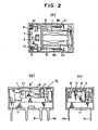
- the holder 7 has a pair of depending legs 7a and 7b formed with respective guide grooves in which movable contact arms 8' and 8" are inserted, respectively, as is shown in Figure 2b.
- the components 1 to 10 mentioned above are mounted on a base plate 11 which carries connector pins A1, A2, B1, B2, C1 and C2 depending downwardly.
- the relay thus assembled, is protected by a cover case 12.
- the iron core 2 is magnetized in a corresponding direction, as a result of which there are formed magnetic poles in the upstanding legs 4a and 4b of the yoke 4.
- the permanent magnet 6 is magnetized as indicated by symbols S and N in Figure 1 and that N-pole makes appearance in the upstanding leg 4b of the yoke 4 through the energization mentioned above.
- the holder 7 holding the movable armature block is moved toward the upstanding leg 4b under magnetic attraction acting between the leg 4b and the permanent magnet 6 as well as under repulsing force acting between the magnet 6 and the leg 4a of the yoke 4.
- Figure 3 of the accompanying drawings graphically illustrates operation characteristics of such bisatable relay and, a broken line curve I, represents intrinsic resilient resistance of the movable contact arms 8' and 8" which has to be overcome by the electromagnetic force during switching operation of the relay.
- This curve I may be referred to as the load characteristic curve.
- the stroke of the movable contact arm performed upon switching operation of the relay is taken along the abscissa.
- the electromagnetic force (actuating force) required to move the movable contact to one of the stationary contacts, e.g. the contact 10 is taken along the lefthand ordinate, while the electromagnetic force (restoring force) required for the restoration of the movable contact 10 to the other stationary contact 9 is taken along the righthand ordinate.
- the relay of monostable type which has only one stable contact state.
- arrangement must be made such that the movable contact closed to one of the stationary contacts, e.g. the contact 10, upon energization of the magnetic coil is restored to the other stationary contact 9 upon deenergization of the coil.
- the operation characteristics of the monostable type relay are graphically illustrated in Figure 4. It will be seen that the movable contact is spontaneously restored to the stationary contact when the coil current is 0%.
- the relay shall be easily mass-produced without requiring troublesome adjustment of the movable contact arms in order to realize the desired operation characteristics.
- the magnetic operating force characteristic is matched with the load characteristic instead of making the latter conform with the former.
- a yoke 13 is of substantially U-like configuration.
- the yoke 13 has a leg 13c at one end to which the core wound with an electromagnetic coil is fixedly connected.
- a pair of upstanding legs 13a and 13b are provided at the other end in opposition to each other with a distance therebetween for accommodating movably the movable armature block constituted by the permanent magnet and other parts as described hereinbefore. It is important to note that the leg 13a is partially cut away in order to reduce the effective area of the magnetic pole when compared with that of the other leg 13b.
- the yoke 13 is incorporated in the structure of the polarized relay in the same manner as the hitherto known relay.
- the movable block In operation, upon electric energization of the magnetic coil, the movable block can be caused to be attracted to the upstanding leg 13a when the magnetization of the permanent magnet 6 and other factors are correspondingly dimensioned, whereby the movable contacts carried by the resilient contact arms are closed to respective ones of the stationary contacts.
- the relay corresponding to excitation current of 0% shown in Figure 4
- the armature is retracted toward the large magnetic pole 13b and thus the movable contacts are restored to the other stationary contact respectively, under the intrinsic restoring resiliency of the movable contact arms which overcomes the sticking force exerted to the small magnetic pole 13a. In this way, the operation characteristics illustrated in Figure 4 can be attained.
- a monostable relay can be easily implemented by using a yoke of the structure according to the invention without need for the subsequent adjustment of the load presented by the movable contact arms. Furthermore, a bistable relay can be readily changed or modified to a monostable relay by merely exchanging the yokes, whereby the manufacturing process of the polarized relays of both operation types can be much facilitated and simplified.
Landscapes
- Physics & Mathematics (AREA)
- Electromagnetism (AREA)
- Electromagnets (AREA)
- Relay Circuits (AREA)
- Pharmaceuticals Containing Other Organic And Inorganic Compounds (AREA)
Claims (3)
Priority Applications (1)
| Application Number | Priority Date | Filing Date | Title |
|---|---|---|---|
| AT84302738T ATE31228T1 (de) | 1983-04-22 | 1984-04-24 | Monostabiles relais. |
Applications Claiming Priority (2)
| Application Number | Priority Date | Filing Date | Title |
|---|---|---|---|
| JP61174/83 | 1983-04-22 | ||
| JP1983061174U JPS59166343U (ja) | 1983-04-22 | 1983-04-22 | 有極リレ− |
Publications (3)
| Publication Number | Publication Date |
|---|---|
| EP0127309A1 EP0127309A1 (de) | 1984-12-05 |
| EP0127309B1 true EP0127309B1 (de) | 1987-12-02 |
| EP0127309B2 EP0127309B2 (de) | 1992-04-01 |
Family
ID=13163519
Family Applications (1)
| Application Number | Title | Priority Date | Filing Date |
|---|---|---|---|
| EP84302738A Expired - Lifetime EP0127309B2 (de) | 1983-04-22 | 1984-04-24 | Monostabiles Relais |
Country Status (6)
| Country | Link |
|---|---|
| US (1) | US4673908A (de) |
| EP (1) | EP0127309B2 (de) |
| JP (1) | JPS59166343U (de) |
| AT (1) | ATE31228T1 (de) |
| CA (1) | CA1234851A (de) |
| DE (1) | DE3467950D1 (de) |
Families Citing this family (1)
| Publication number | Priority date | Publication date | Assignee | Title |
|---|---|---|---|---|
| JPS6112208U (ja) * | 1984-06-25 | 1986-01-24 | 松下電工株式会社 | 電磁石装置 |
Family Cites Families (13)
| Publication number | Priority date | Publication date | Assignee | Title |
|---|---|---|---|---|
| US2881365A (en) * | 1955-11-04 | 1959-04-07 | Nathaniel A Karr | Neutral relay |
| US4064471A (en) * | 1976-03-22 | 1977-12-20 | Leach Corporation | Electromagnetic relay |
| DE2629357A1 (de) * | 1976-06-30 | 1978-01-05 | Elmeg | Monostabiles, elektromagnetisches haftrelais |
| FR2358006A1 (fr) * | 1976-07-09 | 1978-02-03 | Manuf Fse App Electr | Dispositif formant electroaimant, tel que celui d'un relais |
| DE2816555A1 (de) * | 1977-04-18 | 1978-10-19 | Francaise App Elect Mesure | Magnetkreisanordnung fuer einen elektromagneten fuer einen mit einem permanentmagneten als anker |
| JPS564230A (en) * | 1979-05-28 | 1981-01-17 | Kokusai Electric Co Ltd | Etching apparatus utilizing microwave plasma |
| JPS5730232A (en) * | 1980-07-31 | 1982-02-18 | Fujisoku Electric | Self-holding type relay |
| JPS57188816A (en) * | 1981-05-15 | 1982-11-19 | Matsushita Electric Works Ltd | Electromagnet device |
| DE3135171A1 (de) * | 1981-09-04 | 1983-03-17 | Siemens AG, 1000 Berlin und 8000 München | Polarisiertes elektromagnetisches relais |
| FR2520152B1 (fr) * | 1982-01-20 | 1986-02-28 | Telemecanique Electrique | Electro-aimant a equipage mobile a aimant permanent a fonctionnement monostable |
| JPS593904A (ja) * | 1982-06-29 | 1984-01-10 | Omron Tateisi Electronics Co | 有極電磁石ブロツク |
| US4563663A (en) * | 1982-07-16 | 1986-01-07 | Fujisoku Electric Co. Ltd. | Core member for an electromagnetic relay |
| JPS6245411U (de) * | 1985-09-06 | 1987-03-19 |
-
1983
- 1983-04-22 JP JP1983061174U patent/JPS59166343U/ja active Pending
-
1984
- 1984-04-24 DE DE8484302738T patent/DE3467950D1/de not_active Expired
- 1984-04-24 AT AT84302738T patent/ATE31228T1/de not_active IP Right Cessation
- 1984-04-24 CA CA000452647A patent/CA1234851A/en not_active Expired
- 1984-04-24 EP EP84302738A patent/EP0127309B2/de not_active Expired - Lifetime
-
1986
- 1986-01-29 US US06/823,662 patent/US4673908A/en not_active Expired - Lifetime
Also Published As
| Publication number | Publication date |
|---|---|
| DE3467950D1 (en) | 1988-01-14 |
| EP0127309A1 (de) | 1984-12-05 |
| US4673908A (en) | 1987-06-16 |
| CA1234851A (en) | 1988-04-05 |
| ATE31228T1 (de) | 1987-12-15 |
| EP0127309B2 (de) | 1992-04-01 |
| JPS59166343U (ja) | 1984-11-07 |
Similar Documents
| Publication | Publication Date | Title |
|---|---|---|
| US4727344A (en) | Electromagnetic drive and polarized relay | |
| US9275815B2 (en) | Relay having two switches that can be actuated in opposite directions | |
| US4560966A (en) | Polarized electromagnet and polarized electromagnetic relay | |
| US7889032B2 (en) | Electromagnetic relay | |
| EP0670584B1 (de) | Elektromagnetische Einrichtung | |
| JPH09198983A (ja) | 小型デバイス | |
| WO2000060626A8 (en) | Latching magnetic relay assembly with linear motor | |
| CA1292263C (en) | Electromagnetic relay | |
| US4626813A (en) | Electromagnetic drive and polarized relay | |
| MY108274A (en) | Seesaw balance type microminiature electromagnetic relay and method of producing the same. | |
| JP2552418B2 (ja) | 有極リレー | |
| EP0173353B1 (de) | Elektromagnetisches Relais mit linear beweglicher Ankeranordnung | |
| JPH08180785A (ja) | 電磁継電器 | |
| EP0124109B1 (de) | Elektro-magnetisches Relais mit symmetrischer Rückwirkung | |
| EP0127309B2 (de) | Monostabiles Relais | |
| EP0157029A1 (de) | Elektromagnetischer Antrieb und polarisiertes Relais | |
| KR930024041A (ko) | 2조의 전자계전기부를 갖는 소형, 경제적이고 안정한 유극전자계산기 | |
| EP0169542B1 (de) | Polarisiertes elektromagnetisches Relais | |
| EP0277833A2 (de) | Polarisiertes elektromagnetisches Relais | |
| JPH05174691A (ja) | シーソーバランス型有極継電器 | |
| US3959759A (en) | Contact drive for electro-magnetic relays | |
| CN210120089U (zh) | 一种可断开闭合电路的电表连接结构及包含其的电能表 | |
| GB2142188A (en) | Electrical relays | |
| JPH0440251Y2 (de) | ||
| JPH0117076Y2 (de) |
Legal Events
| Date | Code | Title | Description |
|---|---|---|---|
| PUAI | Public reference made under article 153(3) epc to a published international application that has entered the european phase |
Free format text: ORIGINAL CODE: 0009012 |
|
| AK | Designated contracting states |
Designated state(s): AT BE CH DE FR GB IT LI LU NL SE |
|
| 17P | Request for examination filed |
Effective date: 19850604 |
|
| 17Q | First examination report despatched |
Effective date: 19870126 |
|
| GRAA | (expected) grant |
Free format text: ORIGINAL CODE: 0009210 |
|
| AK | Designated contracting states |
Kind code of ref document: B1 Designated state(s): AT BE CH DE FR GB IT LI LU NL SE |
|
| PG25 | Lapsed in a contracting state [announced via postgrant information from national office to epo] |
Ref country code: NL Effective date: 19871202 Ref country code: LI Effective date: 19871202 Ref country code: CH Effective date: 19871202 Ref country code: BE Effective date: 19871202 Ref country code: AT Effective date: 19871202 |
|
| REF | Corresponds to: |
Ref document number: 31228 Country of ref document: AT Date of ref document: 19871215 Kind code of ref document: T |
|
| PG25 | Lapsed in a contracting state [announced via postgrant information from national office to epo] |
Ref country code: SE Effective date: 19871231 |
|
| REF | Corresponds to: |
Ref document number: 3467950 Country of ref document: DE Date of ref document: 19880114 |
|
| ET | Fr: translation filed | ||
| ITF | It: translation for a ep patent filed | ||
| REG | Reference to a national code |
Ref country code: CH Ref legal event code: PL |
|
| PG25 | Lapsed in a contracting state [announced via postgrant information from national office to epo] |
Ref country code: LU Free format text: LAPSE BECAUSE OF NON-PAYMENT OF DUE FEES Effective date: 19880430 |
|
| NLV1 | Nl: lapsed or annulled due to failure to fulfill the requirements of art. 29p and 29m of the patents act | ||
| PLBI | Opposition filed |
Free format text: ORIGINAL CODE: 0009260 |
|
| 26 | Opposition filed |
Opponent name: STANDARD ELEKTRIK LORENZ AG Effective date: 19880825 |
|
| ITTA | It: last paid annual fee | ||
| PUAH | Patent maintained in amended form |
Free format text: ORIGINAL CODE: 0009272 |
|
| STAA | Information on the status of an ep patent application or granted ep patent |
Free format text: STATUS: PATENT MAINTAINED AS AMENDED |
|
| 27A | Patent maintained in amended form |
Effective date: 19920401 |
|
| AK | Designated contracting states |
Kind code of ref document: B2 Designated state(s): AT BE CH DE FR GB IT LI LU NL SE |
|
| REG | Reference to a national code |
Ref country code: CH Ref legal event code: AEN |
|
| ET3 | Fr: translation filed ** decision concerning opposition | ||
| ITF | It: translation for a ep patent filed | ||
| REG | Reference to a national code |
Ref country code: GB Ref legal event code: 746 Effective date: 19970207 |
|
| REG | Reference to a national code |
Ref country code: FR Ref legal event code: D6 |
|
| PGFP | Annual fee paid to national office [announced via postgrant information from national office to epo] |
Ref country code: GB Payment date: 19980220 Year of fee payment: 15 |
|
| PG25 | Lapsed in a contracting state [announced via postgrant information from national office to epo] |
Ref country code: GB Free format text: LAPSE BECAUSE OF NON-PAYMENT OF DUE FEES Effective date: 19990424 |
|
| GBPC | Gb: european patent ceased through non-payment of renewal fee |
Effective date: 19990424 |
|
| PGFP | Annual fee paid to national office [announced via postgrant information from national office to epo] |
Ref country code: FR Payment date: 20030408 Year of fee payment: 20 |
|
| PGFP | Annual fee paid to national office [announced via postgrant information from national office to epo] |
Ref country code: DE Payment date: 20030506 Year of fee payment: 20 |