EP0127485A2 - Palier scellé à roulement à plusieurs rangs - Google Patents
Palier scellé à roulement à plusieurs rangs Download PDFInfo
- Publication number
- EP0127485A2 EP0127485A2 EP84303660A EP84303660A EP0127485A2 EP 0127485 A2 EP0127485 A2 EP 0127485A2 EP 84303660 A EP84303660 A EP 84303660A EP 84303660 A EP84303660 A EP 84303660A EP 0127485 A2 EP0127485 A2 EP 0127485A2
- Authority
- EP
- European Patent Office
- Prior art keywords
- bearing
- annular bodies
- flanges
- bodies
- bearing device
- Prior art date
- Legal status (The legal status is an assumption and is not a legal conclusion. Google has not performed a legal analysis and makes no representation as to the accuracy of the status listed.)
- Granted
Links
Images


Classifications
-
- F—MECHANICAL ENGINEERING; LIGHTING; HEATING; WEAPONS; BLASTING
- F16—ENGINEERING ELEMENTS AND UNITS; GENERAL MEASURES FOR PRODUCING AND MAINTAINING EFFECTIVE FUNCTIONING OF MACHINES OR INSTALLATIONS; THERMAL INSULATION IN GENERAL
- F16C—SHAFTS; FLEXIBLE SHAFTS; ELEMENTS OR CRANKSHAFT MECHANISMS; ROTARY BODIES OTHER THAN GEARING ELEMENTS; BEARINGS
- F16C19/00—Bearings with rolling contact, for exclusively rotary movement
- F16C19/22—Bearings with rolling contact, for exclusively rotary movement with bearing rollers essentially of the same size in one or more circular rows, e.g. needle bearings
- F16C19/34—Bearings with rolling contact, for exclusively rotary movement with bearing rollers essentially of the same size in one or more circular rows, e.g. needle bearings for both radial and axial load
- F16C19/38—Bearings with rolling contact, for exclusively rotary movement with bearing rollers essentially of the same size in one or more circular rows, e.g. needle bearings for both radial and axial load with two or more rows of rollers
- F16C19/383—Bearings with rolling contact, for exclusively rotary movement with bearing rollers essentially of the same size in one or more circular rows, e.g. needle bearings for both radial and axial load with two or more rows of rollers with tapered rollers, i.e. rollers having essentially the shape of a truncated cone
- F16C19/388—Bearings with rolling contact, for exclusively rotary movement with bearing rollers essentially of the same size in one or more circular rows, e.g. needle bearings for both radial and axial load with two or more rows of rollers with tapered rollers, i.e. rollers having essentially the shape of a truncated cone with four rows, i.e. four row tapered roller bearings
-
- B—PERFORMING OPERATIONS; TRANSPORTING
- B21—MECHANICAL METAL-WORKING WITHOUT ESSENTIALLY REMOVING MATERIAL; PUNCHING METAL
- B21B—ROLLING OF METAL
- B21B31/00—Rolling stand structures; Mounting, adjusting, or interchanging rolls, roll mountings, or stand frames
- B21B31/07—Adaptation of roll neck bearings
-
- F—MECHANICAL ENGINEERING; LIGHTING; HEATING; WEAPONS; BLASTING
- F16—ENGINEERING ELEMENTS AND UNITS; GENERAL MEASURES FOR PRODUCING AND MAINTAINING EFFECTIVE FUNCTIONING OF MACHINES OR INSTALLATIONS; THERMAL INSULATION IN GENERAL
- F16C—SHAFTS; FLEXIBLE SHAFTS; ELEMENTS OR CRANKSHAFT MECHANISMS; ROTARY BODIES OTHER THAN GEARING ELEMENTS; BEARINGS
- F16C13/00—Rolls, drums, discs, or the like; Bearings or mountings therefor
- F16C13/02—Bearings
-
- F—MECHANICAL ENGINEERING; LIGHTING; HEATING; WEAPONS; BLASTING
- F16—ENGINEERING ELEMENTS AND UNITS; GENERAL MEASURES FOR PRODUCING AND MAINTAINING EFFECTIVE FUNCTIONING OF MACHINES OR INSTALLATIONS; THERMAL INSULATION IN GENERAL
- F16C—SHAFTS; FLEXIBLE SHAFTS; ELEMENTS OR CRANKSHAFT MECHANISMS; ROTARY BODIES OTHER THAN GEARING ELEMENTS; BEARINGS
- F16C33/00—Parts of bearings; Special methods for making bearings or parts thereof
- F16C33/72—Sealings
- F16C33/76—Sealings of ball or roller bearings
- F16C33/768—Sealings of ball or roller bearings between relatively stationary parts, i.e. static seals
-
- F—MECHANICAL ENGINEERING; LIGHTING; HEATING; WEAPONS; BLASTING
- F16—ENGINEERING ELEMENTS AND UNITS; GENERAL MEASURES FOR PRODUCING AND MAINTAINING EFFECTIVE FUNCTIONING OF MACHINES OR INSTALLATIONS; THERMAL INSULATION IN GENERAL
- F16C—SHAFTS; FLEXIBLE SHAFTS; ELEMENTS OR CRANKSHAFT MECHANISMS; ROTARY BODIES OTHER THAN GEARING ELEMENTS; BEARINGS
- F16C33/00—Parts of bearings; Special methods for making bearings or parts thereof
- F16C33/72—Sealings
- F16C33/76—Sealings of ball or roller bearings
- F16C33/78—Sealings of ball or roller bearings with a diaphragm, disc, or ring, with or without resilient members
- F16C33/7803—Sealings of ball or roller bearings with a diaphragm, disc, or ring, with or without resilient members suited for particular types of rolling bearings
- F16C33/7813—Sealings of ball or roller bearings with a diaphragm, disc, or ring, with or without resilient members suited for particular types of rolling bearings for tapered roller bearings
-
- F—MECHANICAL ENGINEERING; LIGHTING; HEATING; WEAPONS; BLASTING
- F16—ENGINEERING ELEMENTS AND UNITS; GENERAL MEASURES FOR PRODUCING AND MAINTAINING EFFECTIVE FUNCTIONING OF MACHINES OR INSTALLATIONS; THERMAL INSULATION IN GENERAL
- F16C—SHAFTS; FLEXIBLE SHAFTS; ELEMENTS OR CRANKSHAFT MECHANISMS; ROTARY BODIES OTHER THAN GEARING ELEMENTS; BEARINGS
- F16C33/00—Parts of bearings; Special methods for making bearings or parts thereof
- F16C33/72—Sealings
- F16C33/76—Sealings of ball or roller bearings
- F16C33/80—Labyrinth sealings
-
- F—MECHANICAL ENGINEERING; LIGHTING; HEATING; WEAPONS; BLASTING
- F16—ENGINEERING ELEMENTS AND UNITS; GENERAL MEASURES FOR PRODUCING AND MAINTAINING EFFECTIVE FUNCTIONING OF MACHINES OR INSTALLATIONS; THERMAL INSULATION IN GENERAL
- F16C—SHAFTS; FLEXIBLE SHAFTS; ELEMENTS OR CRANKSHAFT MECHANISMS; ROTARY BODIES OTHER THAN GEARING ELEMENTS; BEARINGS
- F16C2322/00—Apparatus used in shaping articles
- F16C2322/12—Rolling apparatus, e.g. rolling stands, rolls
Definitions
- This invention relates to a sealed multi-row roller bearing device for rolling mills.
- a bearing 1 which bears a roll neck 8 inside a bearing box 7 is a 4-row conical roller bearing, wherein, at the opposite ends of the bearing, the outer ends of inner races 2 are axially extended to form inner race extension annular portions 2a, while seal retainer rings 4 are socket-and-spigot-wise removably fitted to the outer end surfaces of outer races 3, so that seal bodies 5 of rubber held in the seal retainer rings 4 are slidably contacted with the outer peripheral surfaces of said inner race extension annular portions 2a, the opposite ends of the bearing 1 being thus sealed by contact type sealing mechanisms 6.
- this bearing not only by a conventional sealing mechanism having contact type seal bodies 9a, 9b, and 9c installed between it and the roll neck 8 at the opposite ends of the bearing box 7, but also in the bearing box, sealing is effected at the opposite ends of th bearing 1 in the bearing box 7, so that entry of cooling water into the bearing 1 is prevented by the two-stage barrier. Further, leakage of grease fed to the bearing 1 is also prevented, so that there is no need to feed grease each time the rolls are exchanged, and hence the consumption of grease can be reduced.
- seal bodies 9a, 9b, and 9c are disposed at the opposite ends of the bearing box 7, the seal bodies 5 can hardly be cooled by cooling water and hence the heat of friction increases to accelerate elasticity degradation.
- a sealing mechanism to be applied to a rolling mill which employs a roll shift mechanism and a strong bender, such as a modern rolling mill must have the ability to cope with a large amount of deflection of the axis in view of a large amount of bending of the rolls.
- the aforesaid contact type sealing mechanism cannot satisfactorily cope with such deflection of the axis, and in this respect, too, there is a problem in the sealing performance.
- the cross-sectional shape of the seal bodies 5 must be similarly enlarged; if not, predetermined sealing performance could not be obtained.
- the width of the sealing mechanism increases and hence the effective width of the bearing correspondingly, reduces, thereby reducing the load carrying capacity.
- the seal retainer rings 4 are simply socket-spigot-wise removably fitted to the outer races 3, there is the danger of their slipping off the outer races when the bearing is attached to and detached form the roll neck, thus resulting in damaging the seal bodies.
- This invention has for its object the provision of a sealed multi-row roller bearing device for rolling mills, wherein the aforesaid problem found in the conventional example is eliminated, when it is applied to the roll neck of a high speed rolling mill sufficient sealing performance is obtained, any deflection of axis can be coped with and hence the sealing effect is not spoiled, the width dimension of the sealing mechanism in the bearing does not increase when the diameter of the bearing is increased, and the handling of the device, as when removed form or installed in the bearing box, is facilitated.
- the outer ends of the inner races are axially extended beyond the ends of the outer races to form inner race extension annular portions.
- inner annular bodies each having respective outward flanges and axially put together and connected by clamp means, and engaged with the outer peripheral surfaces of the inner race extension annular portions so that the inner annular bodies which are inwardly nearest to the bearing cannot be easily separated from the inner race extension annular portions, and a plurality of outer annular bodies each having respective inward flanges and axially put together concentrically with the inner annular bodies so that the inward flanges alternate with the outward flanges to define clearances therebetween, said outer annular bodies being separably connected by clamp means and positioned at the ends of the outer races.
- Fig. 1 is a sectional view showing how a conventional sealed multi-row roller bearing device for rolling mills is installed;
- Fig. 2 is an enlarged sectional view of the sealing mechanism portion thereof;
- Fig. 3 is a sectional view showing how a rolling mill roll neck is supported by the sealed multi-row roller bearing device of this invention;
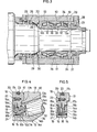
- Figs. 4 to 7 are sectional views showing embodiments of this invention;
- Fig. 8 is a graph showing the result of a comparison between the conventional example and the multi-row roller bearing device of this invention as to their load carrying capacity-increasing tendencies when the inner diameter of the inner races is increased.
- a bearing assembly 10 in this embodiment is an application of a 4-row conical roller bearing supporting the roll neck 11 of a rolling mill in a bearing box 24.
- the small flange end of each inner race 12 is axially extended beyond the end edge of the associated outer race 13 to form an inner race extension annular portion 12a, as shown in Fig. 4.
- outer annular bodies 17 and 18 formed with inward flanges 17a and 18a, respectively are axially put-together concentrically with the inner annular bodies 14, 15, and 16 so that the inward flanges 17a and 18a alternate with the outward flanges 14a, 15a, and 16a of said inner annular bodies 14, 15, and 16, said outer annular bodies being connected and positioned at the end surface of the associated outer race 13.
- a small clearance 19 is defined between the outer peripheries of theinner annular bodies 14, 15, and 16 and the inner peripheries of the outer annular bodies 17 and 18, and thus the regions between the inner and outer races 12 and 13 at the opposite ends of the bearing assembly are sealed by non-contact type sealing devices 20.
- the inner annular bodies 14, 15, and 16 and the outer annular bodies 17 and 18 are so disposed that the order of arrangement of the flanges arranged from the inside to the outside of the bearing assembly 10 is such that an outward flange comes first, and an annular projection 14c formed on the inner peripheral surface of the inner annular body 14 disposed inwardly nearest to the bearing is shrinkage-fitted in an annular races 12b formed in the inner race extension annular portion 12a.
- the connection of the inner annular body 14 to the other inner annular bodies 15 and 16 is effected by clamp fixation using a screw 21 so that they can be separated afterwards.
- the outer annular body 17 has an annular recess 17b formed in its end surface, said recess being removably socket-and-spigot-wise fitted to an annular projection 13a formed o the end surface of the associated outer race 13, and the connection of said outer annular body 17 to the remaining outer annular body 18 is effected by clamp fixation using a screw 22 so that they can be separated afterwards.
- the depth of said socket-and-spigot connection is such that even if the outer annular body 17 is axially moved, its slipping off the outer race 13 due to the presence of the axial clearances defined between the outward and inward flanges is prevented as by making the said depth greater than the axial clearance between the outward flange 16a and the inward flange 18a.
- the attachment of the annular bodies to the bearing assembly 10 is effected in the order of 14, 17, 15, 18, and 16. Further, the maintenance and inspection of the bearing are effected in an order reverse to the annular body attaching order by first removing the screws 21 and 22, then disassembling the annular bodies in the order of 16, 18, 15, and 17, and finally removing the outer race 13 from the bearing assembly 10.
- the inner annular 14 is shrinkage-fitted to the extension annular portion 12a of the inner race 12, it remains together with the inner race 12.
- the numeral 23 denotes an O-ring fitted in a peripheral groove 17c formed in the outer periphery of the outer annular body 17, thereby sealing the region between the inner peripheral surface of the bearing box 24 in which the bearing assembly 10 is housed and the outer peripheral surface of the outer annular body 17. Thereby, the water is prevented from flowing over the outer peripheral surface of the outer annular body 17 and entering the bearing assembly 10 via the fitting region between the outer annular body 17 and the outer race 13.
- the inner race extension annular portion 12a since the inner annular body 14 is shrinkage-fitted thereto, there is no possibility of water entering the bearing assembly 10 across the outer peripheral surface of the inner race extension annular portion 12a.
- peripheral end surfaces of the outward flanges 14a and 16a of the inner annular bodies 14 and 16 and the predetermined inner peripheral surface areas of the outer annular bodies 17 and 18 opposed thereto are tapered so that the openings 19a and 19b of the small clearance 19 defined between the inner annular bodies 14, 15, and 16 the outer annular bodies 17 and 18, which open outwardly and inwardly of the bearing, respectively, are slightly inclined toward the outer diameter.
- This arrangement ensures that water and dust entering the small clearance 19 from the opening 19a are discharged out of the small clearance 19 by the centrifugal force developed by the rotation of the inner race 12 and that, on the inner side of the bearing, grease entering the small clearance 19 from the opening 19b is similarly centrifugally pushed back into the bearing assembly 10.
- the numerals 25, 26, and 27 denote contact type end seal bodies which seal between the beairng box 24 and the roll neck 11 at the opposite ends of the bearing box 24 axially separated form the interior where the bearing assembly 10 is housed, said seal bodies serving to prevent entry of water and dust from the opposite ends of the bearing box 24.
- the numeral 33 denotes conical rollers
- 34 denotes a retainer formed of a steel sheet.
- FIG. 5 A second embodiment of this invention is shown in Fig. 5.
- the coating with non-metal material may be applied to the outer peripheral surfaces of the inner annular bodies 14, 15, and 16 instead of to the outer annular bodies 17 and 18, or the outer annular bodies 17 and 18 or the inner annular bodies 14, 15, and 16 may be made entirely of non-metal material, or these may be optionally combined.
- the openings 19a and 19b of the small clearance 19 are not inclined toward the outer diameter, but they may be inclined as in Fig. 4. The rest of the arrangement is the same as in the preceding embodiment.
- FIG. 6 A third embodiment of this invention is shown in Fig. 6.
- the one exposed at the outermost side is made thicker than the other flanges.
- This arrangement prevents the sealing devices 20 from being damaged when struck by other members or subjected to an impact form the outside.
- the outward flange 16a of the inner annular body 16 is made thicker, but there are cases where the inward flange of the outer annular body would be exposed at the outermost side depending upon the number of annular bodies combined and the order of arrangement, in which case it will be made thicker. The rest of the arrangement is the same as in the first embodiment.
- FIG. 7 A fourth embodiment of this invention is shown in Fig. 7.
- Fig. 8 shows the result of a comparison between the bearing and the previously described conventional bearing as to their tendencies to increase the load carrying capacity as the inner diameter of the bearings is increased.
Landscapes
- Engineering & Computer Science (AREA)
- General Engineering & Computer Science (AREA)
- Mechanical Engineering (AREA)
- Rolling Contact Bearings (AREA)
- Sealing Using Fluids, Sealing Without Contact, And Removal Of Oil (AREA)
- Sealing Of Bearings (AREA)
- Rolls And Other Rotary Bodies (AREA)
Applications Claiming Priority (2)
| Application Number | Priority Date | Filing Date | Title |
|---|---|---|---|
| JP58097637A JPS59223103A (ja) | 1983-05-31 | 1983-05-31 | 圧延機における密封形多列ころ軸受 |
| JP97637/83 | 1983-05-31 |
Publications (4)
| Publication Number | Publication Date |
|---|---|
| EP0127485A2 true EP0127485A2 (fr) | 1984-12-05 |
| EP0127485A3 EP0127485A3 (en) | 1985-05-29 |
| EP0127485B1 EP0127485B1 (fr) | 1987-09-09 |
| EP0127485B2 EP0127485B2 (fr) | 1991-08-28 |
Family
ID=14197652
Family Applications (1)
| Application Number | Title | Priority Date | Filing Date |
|---|---|---|---|
| EP84303660A Expired - Lifetime EP0127485B2 (fr) | 1983-05-31 | 1984-05-31 | Palier scellé à roulement à plusieurs rangs |
Country Status (4)
| Country | Link |
|---|---|
| US (1) | US4527915A (fr) |
| EP (1) | EP0127485B2 (fr) |
| JP (1) | JPS59223103A (fr) |
| DE (1) | DE3465900D1 (fr) |
Cited By (3)
| Publication number | Priority date | Publication date | Assignee | Title |
|---|---|---|---|---|
| GB2174765A (en) * | 1985-05-06 | 1986-11-12 | Torrington Co | Multirow roller bearing |
| EP0608672A1 (fr) * | 1993-01-27 | 1994-08-03 | Skf Mekan Ab | Joint à labyrinthes pour chapeaux de paliers lubrifiés à l'huile |
| CN103322204A (zh) * | 2013-06-29 | 2013-09-25 | 济钢集团有限公司 | 一种酸洗线破鳞拉矫机导向辊的轴承密封装置 |
Families Citing this family (20)
| Publication number | Priority date | Publication date | Assignee | Title |
|---|---|---|---|---|
| DE3503344A1 (de) * | 1985-02-01 | 1986-08-07 | FAG Kugelfischer Georg Schäfer KGaA, 8720 Schweinfurt | Dichtung fuer angetriebene rollen in stranggiessanlagen |
| US4707150A (en) * | 1987-01-14 | 1987-11-17 | Disposable Waste Systems, Inc. | Fluid pressure assisted rotary shaft seal with grooved seal wedge |
| DE8708234U1 (de) * | 1987-06-11 | 1987-07-30 | SKF GmbH, 8720 Schweinfurt | Berührungsfreie Abdichtung eines Lagers |
| JPH0724617Y2 (ja) * | 1988-06-03 | 1995-06-05 | 三菱電機株式会社 | オーバハング型スタータ |
| SE461803B (sv) * | 1989-03-17 | 1990-03-26 | Skf Mekanprodukter Ab | Anordning foer montering av ett lager paa en axel |
| US5074567A (en) * | 1989-04-10 | 1991-12-24 | Orlowski David C | Modified one piece labyrinth seal |
| US5272785A (en) * | 1989-12-26 | 1993-12-28 | The Scott Fetzer Company | Brushroll |
| US5465451A (en) * | 1989-12-26 | 1995-11-14 | The Scott Fetzer Company | Brushroll |
| DE4311300C1 (de) * | 1993-04-06 | 1994-02-24 | Witels App Masch Albert Gmbh | Richtapparat für drahtförmiges, mehrdrahtförmiges oder rohrförmiges Richtgut |
| US5676472A (en) * | 1995-07-10 | 1997-10-14 | Smart Machines | Rotary labyrinth seal |
| JP3646467B2 (ja) * | 1996-07-31 | 2005-05-11 | 日本精工株式会社 | 転がり軸受 |
| JP2001304278A (ja) | 1999-10-08 | 2001-10-31 | Nsk Ltd | 密封形軸受装置 |
| KR100880574B1 (ko) * | 2002-08-07 | 2009-01-30 | 주식회사 포스코 | 열간 압연 쵸크 및 베어링 열화 방지 냉각 장치 |
| DE102004025796A1 (de) * | 2004-05-26 | 2005-12-22 | Fag Kugelfischer Ag & Co. Ohg | Abgedichtetes Wälzlager, insbesondere abgedichtetes vierreihiges Kegelrollenlager für Stütz- und Arbeitswalzenlagerungen an Walzgerüsten |
| BE1017166A3 (fr) * | 2006-06-13 | 2008-03-04 | Hansen Transmissions Int | |
| DE102012200674B4 (de) * | 2012-01-18 | 2016-09-29 | Schaeffler Technologies AG & Co. KG | Zwei- oder mehrreihiges Schrägkugellager |
| CN102818026B (zh) * | 2012-08-08 | 2015-04-15 | 东南大学 | 一种用于立式主轴的离心和迷宫组合密封装置 |
| CN102878299A (zh) * | 2012-10-19 | 2013-01-16 | 无锡京华重工装备制造有限公司 | 一种旋转主轴密封结构 |
| DE102018201885A1 (de) * | 2018-02-07 | 2019-08-08 | Aktiebolaget Skf | Abgedichtetes Lagermodul |
| CN111659862A (zh) * | 2020-06-05 | 2020-09-15 | 中国重型机械研究院股份公司 | 一种高拉速小方坯导向段辊子装配装置及方法 |
Family Cites Families (11)
| Publication number | Priority date | Publication date | Assignee | Title |
|---|---|---|---|---|
| US1991077A (en) * | 1931-01-26 | 1935-02-12 | Gen Motors Corp | Seal or guard |
| US1916682A (en) * | 1932-06-04 | 1933-07-04 | Pioneer Gravel Equipment Mfg C | Bearing structure |
| US2176294A (en) * | 1938-03-26 | 1939-10-17 | Timken Roller Bearing Co | End closure for axle housings |
| US2868574A (en) * | 1957-09-13 | 1959-01-13 | Morgan Construction Co | Seal |
| DE1897911U (de) * | 1961-10-14 | 1964-08-06 | Kugelfischer G Schaefer & Co | Lagerung fuer walzgerueste. |
| US3343891A (en) * | 1964-07-06 | 1967-09-26 | Kaiser Steel Corp | Seal device |
| JPS529367B2 (fr) * | 1972-08-23 | 1977-03-15 | ||
| US3833273A (en) * | 1973-07-30 | 1974-09-03 | Morgan Construction Co | Labyrinth type seal |
| US4093324A (en) * | 1977-05-16 | 1978-06-06 | Emerson Electric Co. | Seal for self-aligning bearing |
| DE7935867U1 (de) * | 1979-12-20 | 1980-03-27 | Fag Kugelfischer Georg Schaefer & Co, 8720 Schweinfurt | Abgedichtetes Wälzlager |
| JPS5759850A (en) * | 1980-09-30 | 1982-04-10 | Daikin Ind Ltd | Polyfluoroallyl ether and its preparation and use |
-
1983
- 1983-05-31 JP JP58097637A patent/JPS59223103A/ja active Granted
-
1984
- 1984-05-29 US US06/615,901 patent/US4527915A/en not_active Expired - Fee Related
- 1984-05-31 EP EP84303660A patent/EP0127485B2/fr not_active Expired - Lifetime
- 1984-05-31 DE DE8484303660T patent/DE3465900D1/de not_active Expired
Cited By (6)
| Publication number | Priority date | Publication date | Assignee | Title |
|---|---|---|---|---|
| GB2174765A (en) * | 1985-05-06 | 1986-11-12 | Torrington Co | Multirow roller bearing |
| GB2174765B (en) * | 1985-05-06 | 1989-05-10 | Torrington Co | Multirow roller bearing |
| AT392523B (de) * | 1985-05-06 | 1991-04-25 | Torrington Co | Mehrreihiges lager |
| EP0608672A1 (fr) * | 1993-01-27 | 1994-08-03 | Skf Mekan Ab | Joint à labyrinthes pour chapeaux de paliers lubrifiés à l'huile |
| CN103322204A (zh) * | 2013-06-29 | 2013-09-25 | 济钢集团有限公司 | 一种酸洗线破鳞拉矫机导向辊的轴承密封装置 |
| CN103322204B (zh) * | 2013-06-29 | 2015-10-21 | 济钢集团有限公司 | 一种酸洗线破鳞拉矫机导向辊的轴承密封装置 |
Also Published As
| Publication number | Publication date |
|---|---|
| JPH0366963B2 (fr) | 1991-10-21 |
| DE3465900D1 (en) | 1987-10-15 |
| US4527915A (en) | 1985-07-09 |
| JPS59223103A (ja) | 1984-12-14 |
| EP0127485B2 (fr) | 1991-08-28 |
| EP0127485A3 (en) | 1985-05-29 |
| EP0127485B1 (fr) | 1987-09-09 |
Similar Documents
| Publication | Publication Date | Title |
|---|---|---|
| US4527915A (en) | Sealed multi-row roller bearing device for rolling mills | |
| US4630458A (en) | Seal arrangement for mill roll | |
| US4159152A (en) | Means for lubricating the roll neck/sleeve interface of an oil film bearing | |
| US2740647A (en) | Bearing construction | |
| US5118206A (en) | Cone bore seal | |
| JP3764740B2 (ja) | ネックシール | |
| US9958009B2 (en) | Roller bearing | |
| EP0703840B1 (fr) | Joint et manchon verrouilles reciproquement pour palier a film d'huile de laminoire | |
| US10731707B2 (en) | Sealed bearing module | |
| US4139203A (en) | Labyrinth type rotary seal with intermittent feature of contact type seal | |
| US4323287A (en) | Bearing seal | |
| US5186547A (en) | Roller bearing and seal assembly | |
| JPS5821145B2 (ja) | 圧延ロ−ルのベアリング用の弾性密封体 | |
| US4910987A (en) | Roll neck face seal for cantilevered rolling mill | |
| US10550891B2 (en) | Seal member for rolling bearing and rolling bearing assembly | |
| US6345914B1 (en) | Sealed rolling bearing with centrifugal feature | |
| EP0997673B1 (fr) | Dispositif d'étanchéité pour palier et palier support de cylindre de laminage comportant un tel dispositif d'étanchéité | |
| US4265456A (en) | Sealing assembly | |
| US3093425A (en) | Seal for rolling mill | |
| JP2522930Y2 (ja) | 圧延機用多列ころ軸受装置の潤滑装置 | |
| SU1754244A1 (ru) | Подшипникова опора т желонагруженного прокатного валка | |
| JP2009097665A (ja) | 軸受装置 | |
| JPS59222620A (ja) | 軸受の密封装置 | |
| JP2002372059A (ja) | 軸受装置 | |
| JPS6112130B2 (fr) |
Legal Events
| Date | Code | Title | Description |
|---|---|---|---|
| PUAI | Public reference made under article 153(3) epc to a published international application that has entered the european phase |
Free format text: ORIGINAL CODE: 0009012 |
|
| AK | Designated contracting states |
Designated state(s): DE GB |
|
| PUAL | Search report despatched |
Free format text: ORIGINAL CODE: 0009013 |
|
| AK | Designated contracting states |
Designated state(s): DE GB |
|
| 17P | Request for examination filed |
Effective date: 19850401 |
|
| 17Q | First examination report despatched |
Effective date: 19860219 |
|
| GRAA | (expected) grant |
Free format text: ORIGINAL CODE: 0009210 |
|
| AK | Designated contracting states |
Kind code of ref document: B1 Designated state(s): DE GB |
|
| REF | Corresponds to: |
Ref document number: 3465900 Country of ref document: DE Date of ref document: 19871015 |
|
| PLBI | Opposition filed |
Free format text: ORIGINAL CODE: 0009260 |
|
| 26 | Opposition filed |
Opponent name: SMS SCHLOEMANN-SIEMAG AG Effective date: 19880607 |
|
| PUAH | Patent maintained in amended form |
Free format text: ORIGINAL CODE: 0009272 |
|
| STAA | Information on the status of an ep patent application or granted ep patent |
Free format text: STATUS: PATENT MAINTAINED AS AMENDED |
|
| 27A | Patent maintained in amended form |
Effective date: 19910828 |
|
| AK | Designated contracting states |
Kind code of ref document: B2 Designated state(s): DE GB |
|
| PGFP | Annual fee paid to national office [announced via postgrant information from national office to epo] |
Ref country code: GB Payment date: 19950522 Year of fee payment: 12 |
|
| PGFP | Annual fee paid to national office [announced via postgrant information from national office to epo] |
Ref country code: DE Payment date: 19950523 Year of fee payment: 12 |
|
| PG25 | Lapsed in a contracting state [announced via postgrant information from national office to epo] |
Ref country code: GB Effective date: 19960531 |
|
| GBPC | Gb: european patent ceased through non-payment of renewal fee |
Effective date: 19960531 |
|
| PG25 | Lapsed in a contracting state [announced via postgrant information from national office to epo] |
Ref country code: DE Effective date: 19970201 |