EP0127496A1 - Vorrichtung zur Erzeugung infraroter oder ultravioletter Strahlung - Google Patents
Vorrichtung zur Erzeugung infraroter oder ultravioletter Strahlung Download PDFInfo
- Publication number
- EP0127496A1 EP0127496A1 EP84400792A EP84400792A EP0127496A1 EP 0127496 A1 EP0127496 A1 EP 0127496A1 EP 84400792 A EP84400792 A EP 84400792A EP 84400792 A EP84400792 A EP 84400792A EP 0127496 A1 EP0127496 A1 EP 0127496A1
- Authority
- EP
- European Patent Office
- Prior art keywords
- longitudinal
- shield
- tube
- elements
- strip
- Prior art date
- Legal status (The legal status is an assumption and is not a legal conclusion. Google has not performed a legal analysis and makes no representation as to the accuracy of the status listed.)
- Granted
Links
Images





Classifications
-
- F—MECHANICAL ENGINEERING; LIGHTING; HEATING; WEAPONS; BLASTING
- F21—LIGHTING
- F21V—FUNCTIONAL FEATURES OR DETAILS OF LIGHTING DEVICES OR SYSTEMS THEREOF; STRUCTURAL COMBINATIONS OF LIGHTING DEVICES WITH OTHER ARTICLES, NOT OTHERWISE PROVIDED FOR
- F21V7/00—Reflectors for light sources
- F21V7/005—Reflectors for light sources with an elongated shape to cooperate with linear light sources
-
- F—MECHANICAL ENGINEERING; LIGHTING; HEATING; WEAPONS; BLASTING
- F24—HEATING; RANGES; VENTILATING
- F24C—DOMESTIC STOVES OR RANGES ; DETAILS OF DOMESTIC STOVES OR RANGES, OF GENERAL APPLICATION
- F24C1/00—Stoves or ranges in which the fuel or energy supply is not restricted to solid fuel or to a type covered by a single one of the following groups F24C3/00 - F24C9/00; Stoves or ranges in which the type of fuel or energy supply is not specified
- F24C1/08—Stoves or ranges in which the fuel or energy supply is not restricted to solid fuel or to a type covered by a single one of the following groups F24C3/00 - F24C9/00; Stoves or ranges in which the type of fuel or energy supply is not specified solely adapted for radiation heating
- F24C1/10—Stoves or ranges in which the fuel or energy supply is not restricted to solid fuel or to a type covered by a single one of the following groups F24C3/00 - F24C9/00; Stoves or ranges in which the type of fuel or energy supply is not specified solely adapted for radiation heating with reflectors
-
- F—MECHANICAL ENGINEERING; LIGHTING; HEATING; WEAPONS; BLASTING
- F24—HEATING; RANGES; VENTILATING
- F24C—DOMESTIC STOVES OR RANGES ; DETAILS OF DOMESTIC STOVES OR RANGES, OF GENERAL APPLICATION
- F24C15/00—Details
- F24C15/22—Reflectors for radiation heaters
-
- F—MECHANICAL ENGINEERING; LIGHTING; HEATING; WEAPONS; BLASTING
- F26—DRYING
- F26B—DRYING SOLID MATERIALS OR OBJECTS BY REMOVING LIQUID THEREFROM
- F26B3/00—Drying solid materials or objects by processes involving the application of heat
- F26B3/28—Drying solid materials or objects by processes involving the application of heat by radiation, e.g. from the sun
- F26B3/30—Drying solid materials or objects by processes involving the application of heat by radiation, e.g. from the sun from infrared-emitting elements
Definitions
- the present invention relates to a device intended for the production and diffusion by reflection of infrared or ultraviolet radiation.
- Devices of this type are known, being in the form of panels capable of being used, for example, in the stationery, textile, plastics, etc. industries. Infrared panels are also used in tunnel ovens, for example for baking bread in an industrial bakery, or for drying paint in the automotive industry.
- This device relates to the actual lighting and does not concern infrared radiation.
- the opening angle corresponding to the lost radiation is 110 degrees, which represents 30% of the total radiation.
- no ventilation is provided.
- Such a structure could not be implemented at a temperature of 2700 ° K like that which must prevail in the devices according to the invention.
- a ray reflector device comprising an elongated reflector body having a curved support surface for a reflective strip which is pressed against this support surface.
- an air gap passes between two reflectors and causes a Venturi phenomenon causing corrosive vapors which "lick" the emitter and the reflective part of the reflector.
- the present invention aims to avoid these drawbacks, by providing a device for the production and reflection of infrared radiation, under the form of a panel grouping several transmitting rods behind which are reflective means, characterized in that the rods are arranged at equal distance and parallel to each other, inside a rectangular frame while, behind the rods , is a reflector, the overall shape of which consists of a succession of concave gutters, each placed behind a transmitting rod, each gutter being defined by the juxtaposition of two longitudinal elements, each of which has a V-shaped cross section, the two of which branches are concave on the outside, the junction gap of two juxtaposed elements being masked by a longitudinal shield placed at this location behind the two elements, each of which is self-supporting.
- each of the longitudinal elements with a concave V-shaped section consists of a metal sheet folded according to this V-shaped profile, so that it is not only self-supporting, but also capable of deforming elastically under the effect of variable thermal stresses, of the kind that one encounters for example if one varies, during operation, the power of radiation, and therefore the wavelength of the rays emitted.
- a reflector for infrared emitting tubes comprising a juxtaposition of rear shields and elements in two half-gutters, and characterized in that at least the elements in two half-gutters are hollow, their interior space being traversed by a cooling fluid.
- the rear shields are also hollow and double wall, their interior space being traversed by a cooling fluid.
- the cooling fluid which circulates in the double walls of the reflector can be, for example, blown air.
- the device according to the invention intended to mask the radiation emitted by a tube in the direction of a gap defined in the reflector located behind this tube, is characterized in that the shield consists of an opaque strip applied along a part of the rear surface of the radiating tube.
- the metal strip forming the shield is formed by a metallization deposit carried out directly on the wall of the tube, which then takes the form of an ordinary tube, opacified only along '' a reflective strip, made of metal or ceramic.
- the shield is constituted by a concave metal strip, made of sheet metal, attached against a pirtie of the rear longitudinal wall of the tube.
- the width of this metal band in the shape of a gutter is significantly less than the diameter of the tube.
- the concave metal gutter constituting the shield is fixed on the tube by elastic clipping, so that when you change a tube, you can use the shield of the old on the new tube.
- each V-shaped element of the reflector has at least its reflecting surface formed by a layer or a sheet of gold or other metals.
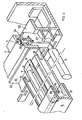
- a panel 1 used both to produce infrared radiation, and to diffuse it by reflection over its entire surface.
- the panel is constituted by a frame formed by two crosspieces 2, and two longitudinal members 3 and 4. On the rectangular frame thus produced, are placed side by side and parallel to each other, emitting rods 5 made of quartz. Each of the rods 5 is disposed inside the frame, parallel to the crosspieces 2, one end of each rod 5 being carried by the beam 4, while the other is carried by the beam 3.
- the latter also has electrical connection means constituted in particular by studs 6, to supply the quartz rods 5.
- the rods 5 are distributed on the front face of the panel 1, the rear face of which is occupied by a reflector 7. The whole of the latter is formed by the juxtaposition of V-shaped elements 8, and rear shields 9 ( Figure 5 ).
- Each V-shaped element 8 is constituted by a sheet folded along a cross section having the shape of a V, the lateral faces 10 and 11 of which are concave towards the outside.
- Each lateral face 10 or 11 of the V is surmounted by a rim 12 or 13, itself surmounted by a tab 14 or 15, slightly folded inwards.
- a longitudinal notch 16 is preferably provided, for each end of the vertical flanges 12 and 13, in the wings 21 and 23.
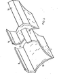
- Each shield 9 is constituted by a simple strip of sheet metal, curved according to a transverse profile in an arc of a circle, which allows it, too, to be self-supporting.
- the width 17 of each shield 9 is greater than or equal to the distance 18 separating the divergent ends of the two legs 14 and 15, juxtaposed after assembly ( Figure 5).
- the support of the V-shaped elements 8 is constituted by simple pins which support the ends of the legs 14,15.
- three pins are provided at each end, one at center of the concave part, and two at the ends of the convex part.
- V-shaped elements 8 are arranged side by side, longitudinally, each vertical rim 12 of one being immediately adjacent to the vertical rim 13 of the adjacent element.
- a longitudinal reflecting gutter 19 there is thus defined around each quartz rod 5, a longitudinal reflecting gutter 19, the apex of which has a longitudinal connection gap 20.
- This gap corresponds to the distance separating two adjacent edges 12 and 13, and its width may vary during operation in function of the evolution of the variations of power, and, consequently, of temperatures.
- each gap 20 is closed off by covering it with a longitudinal shield 9, arranged in the manner illustrated in FIGS. 2 and 5. Thanks to this arrangement, it is certain that all of the radiation emitted by each rod 5 in all directions is returned towards the front of the panel 1.
- the spar 4 preferably comprises a U-shaped section, the lower wing 21 of which is fitted by the notches 16 fitted to the corresponding end of each V-shaped element 8.
- each spar 3 has a U-shaped section 22, the horizontal lower wing 23 of which has notches 16 for the corresponding end of each V-shaped element 8.
- Each electrical connection pad 6 is preferably constituted by a metallic connection lug 24, equipping a horizontal support wing 25 of the beam 3, with interposition of sleeves 26 of insulating material.
- the lower metal end of each stud 24 is connected to a supply tab 27, which supports the corresponding end of the quartz cane 5, while ensuring its electrical supply.
- the shields 9 covering two folded legs 14 and 15 juxtaposed are preferably held in place by engagement under the upper wing 28 or 29, of the corresponding U-shaped iron, 4 or 22.
- each reflecting gutter 19 can correspond to any suitable mathematical form, in particular circular, elliptical or parabolic.
- the width 18 of the shield 9 is calculated accordingly, to completely mask the radiation towards the rear passing through the gap 20.
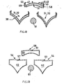
- Figures 6, 7 and 12 show a reflector element in the form of two half-gutters, produced by assembling two elementary parts 31 and 32.
- the part 31 is made of folded sheet metal, in a V-shaped cross section with two curvilinear branches 33 and 34, each surmounted by a vertical flange referenced respectively 35 and 36.
- the part 32 has a cross section identical to that of the part 31 (FIG. 6).
- the part 31 is embedded in the part 32, which is accompanied by an elastic deformation to engage the edges 35 and 36 of the part 31 between the edges 45 and 46 of the part 32.
- the amplitude of this deformation corresponds to the thickness 37 of the sheet of each of these parts.
- the interlocking of parts 31 and 32 into one another is not carried out completely, so as to leave between them, a gap 38 corresponding to a double wall extending over the entire length of the curved wings of the section in V.
- a weld bead 39 is placed on each side, which joins the flanges 35 and 45, and 40, to join the flanges 36 and 46.
- the rear shield of the reflector is defined by fitting one into the other of two parts 41 and 42, identical to each other.
- the part 41 is made of sheet metal folded along a cross section in an arc of a circle 43, raised at each end along two flanges 47 and 48.
- the part 42 also has a cross section in an arc 44, located between two flanges 49 and 50.
- the part 41 is forced into place between the flanges 49 and 50 of the part 42.
- This movement is carried out with a elastic deformation, the magnitude of which corresponds to the thickness of the sheet.
- the embedding is not carried out completely, so as to leave between the two arcs 43 and 44, a free gap 51 ( Figure 12).
- the assembly is carried out by placing a weld bead 52 on the flanges 47 and 49, while a similar weld bead 53 assembles the flanges 48 and 50.
- each element in two half-gutters 54 is produced in one piece in the form of a folded sheet metal strip, the cross section of which defines as above, the two curved wings 33 and 34 of a V, and the two lateral flanges 35 and 36.
- these two flanges are each surmounted by a longitudinal tab 55, 56.
- These two tabs are folded one in the direction of the other, and they overlap in their connection zone, where they are assembled by a weld bead 57.
- the reflective element 54 is therefore in the form of a tube whose cross section has substantially the shape of a triangle, whose two sides are curvilinear.
- each shield 58 of this reflector is formed by folding over itself a single sheet metal strip, with a cross section which comprises an arc of a circle 44, taken between two folded edges 49 and 50, which two legs extend longitudinal 59 and 60, folded towards each other, up to their connection zone where they overlap. In this zone, a weld bead 51 completes the assembly.
- the operation is as follows.
- each of the elements 31, 32, 41, 42 or 54, 58, of the reflector being made with double wall, it has an interior space 38, 51 or 62, 63, in which a refrigerant, for example air, or even water.
- a refrigerant for example air, or even water.
- the heating power of the tubes 61 can be considerably increased, while keeping the entire reflector at a relatively low temperature. This protects, among other things, the rear area of the reflector against inadvertent overheating.
- the presence of a gap between two neighboring reflective elements generates both the loss of infrared radiation and causes excessive heating of the rear region of the cassette.
- a shield can be provided as shown in Figures 14 to 19.
- FIG. 14 shows a part of a cassette of known type, used as a generator of infrared radiation.
- This cassette notably comprises radiation emitting tubes 71, each located opposite a reflective gutter 72.
- the entire reflector is formed by a juxtaposition of several elements reflectors 73, each having a V-shaped cross section, the two wings of which are concave.
- the base of the V of each element 73 defines a longitudinal edge 74.
- each gutter 72 is defined between two successive edges 74, formed by two half-gutters 75 and 76, corresponding to two different elements 73.
- the junction between the two half-gutters 75 and 76 takes place at the bottom of the gutter 72, along a longitudinal gap 77.
- each emitter tube 83 according to the invention is then provided with its own shield 82, visible in the form of a narrow metal strip, arranged longitudinally on the wall of the tube.
- the metal strip 82 constituting the shield is produced on the contrary in the form of a removable strip, that is to say a narrow strip of sheet metal than elastic staples 84 allow to snap lightly on the tube 83.
- the metal strip 82 constituting the shield is provided, on its back, with hooking clips 85, each of which is formed by a tubular spacer 86, by a screw 87, and a bar 88 which can be removably hooked (Figure 18) on the ribs 89 located at the top of the two half-gutters 75 and 76, on either side of the gap 77.
- the shield 82 is fixed between the tube 71 and the gap 77 which it masks, while allowing the air to circulate freely therein.
Landscapes
- Engineering & Computer Science (AREA)
- General Engineering & Computer Science (AREA)
- Chemical & Material Sciences (AREA)
- Combustion & Propulsion (AREA)
- Mechanical Engineering (AREA)
- Life Sciences & Earth Sciences (AREA)
- Microbiology (AREA)
- Radiation-Therapy Devices (AREA)
- Blinds (AREA)
- Paints Or Removers (AREA)
Priority Applications (1)
| Application Number | Priority Date | Filing Date | Title |
|---|---|---|---|
| AT84400792T ATE30785T1 (de) | 1983-04-25 | 1984-04-19 | Vorrichtung zur erzeugung infraroter oder ultravioletter strahlung. |
Applications Claiming Priority (6)
| Application Number | Priority Date | Filing Date | Title |
|---|---|---|---|
| FR8307082 | 1983-04-25 | ||
| FR8307082A FR2544873B1 (fr) | 1983-04-25 | 1983-04-25 | Dispositif pour la production et la reflexion d'un rayonnement infrarouge |
| FR8318066A FR2554560B1 (fr) | 1983-11-08 | 1983-11-08 | Dispositif reflecteur pour un appareil de chauffage par rayonnements infra-rouges |
| FR8318066 | 1983-11-08 | ||
| FR8318063A FR2554556A1 (fr) | 1983-11-08 | 1983-11-08 | Dispositif de bouclier pour la protection arriere d'un appareil emetteur de rayonnements infra-rouges, tubes et boucliers pour sa mise en oeuvre |
| FR8318063 | 1983-11-08 |
Publications (2)
| Publication Number | Publication Date |
|---|---|
| EP0127496A1 true EP0127496A1 (de) | 1984-12-05 |
| EP0127496B1 EP0127496B1 (de) | 1987-11-11 |
Family
ID=27251158
Family Applications (1)
| Application Number | Title | Priority Date | Filing Date |
|---|---|---|---|
| EP84400792A Expired EP0127496B1 (de) | 1983-04-25 | 1984-04-19 | Vorrichtung zur Erzeugung infraroter oder ultravioletter Strahlung |
Country Status (8)
| Country | Link |
|---|---|
| US (1) | US4596935A (de) |
| EP (1) | EP0127496B1 (de) |
| AU (1) | AU560622B2 (de) |
| BR (1) | BR8401897A (de) |
| DE (1) | DE3467420D1 (de) |
| DK (1) | DK205884A (de) |
| FI (1) | FI841491A7 (de) |
| NO (1) | NO841554L (de) |
Cited By (3)
| Publication number | Priority date | Publication date | Assignee | Title |
|---|---|---|---|---|
| FR2596212A1 (fr) * | 1986-03-24 | 1987-09-25 | Lumpp Christian | Dispositif de support, de positionnement et de liaison electrique pour un tube emetteur de rayonnement |
| FR2649781A1 (fr) * | 1989-07-17 | 1991-01-18 | Lumpp Christian | Dispositif de ventilation et de refroidissement pour cassette support d'emetteurs uv |
| EP2693126A2 (de) | 2012-08-02 | 2014-02-05 | Andrzej Wronski | Belüftungssystem für Heizstrahler, insbesondere für einen Heizstrahler mit einem Infrarot-Röhrenstrahler, und Heizstrahler mit solch einem System |
Families Citing this family (36)
| Publication number | Priority date | Publication date | Assignee | Title |
|---|---|---|---|---|
| FR2623634B1 (fr) * | 1987-11-25 | 1991-08-16 | Armines | Appareil emetteur de rayonnement infrarouge comportant une source plane de rayons infrarouges et un reflecteur |
| FR2623633B1 (fr) * | 1987-11-25 | 1991-08-16 | Armines | Appareil emetteur de rayonnement infrarouge comportant au moins une source cylindrique de rayons infrarouges et un reflecteur |
| US5003185A (en) * | 1988-11-17 | 1991-03-26 | Burgio Joseph T Jr | System and method for photochemically curing a coating on a substrate |
| US5177977A (en) * | 1989-04-11 | 1993-01-12 | Larsen Theodore E | Solar energy collector and reradiation apparatus for localized climate control |
| US5138175A (en) * | 1989-09-14 | 1992-08-11 | Lehigh University | Lamp sheath assembly for optically-assisted gas decontamination process |
| US5083030A (en) * | 1990-07-18 | 1992-01-21 | Applied Photonics Research | Double-sided radiation-assisted processing apparatus |
| US5055697A (en) * | 1990-08-24 | 1991-10-08 | Electro-Mechanical Imagineering, Inc. | Infrared radiator |
| USRE36896E (en) * | 1993-03-05 | 2000-10-03 | Trojan Technologies Inc. | Fluid treatment system and process |
| TW317558B (de) * | 1993-03-05 | 1997-10-11 | Trotan Technologies Inc | |
| US5537925A (en) * | 1993-09-03 | 1996-07-23 | Howard W. DeMoore | Infra-red forced air dryer and extractor |
| US5471063A (en) * | 1994-01-13 | 1995-11-28 | Trojan Technologies, Inc. | Fluid disinfection system |
| US5514871A (en) * | 1994-01-13 | 1996-05-07 | Trojan Technologies | Optical radiation sensor device |
| US5433140A (en) * | 1994-08-29 | 1995-07-18 | Ogee; Larry S. | Illuminated bread box |
| JPH08174567A (ja) * | 1994-10-25 | 1996-07-09 | Ushio Inc | 光照射器 |
| US5726815A (en) * | 1996-04-12 | 1998-03-10 | Fusion Uv Systems, Inc. | Apparatus for aligning the object focus in filament irradiating units |
| US5910659A (en) * | 1996-04-30 | 1999-06-08 | The United States Of America As Represented By The Secretary Of Commerce | Flat panel thermal infrared generator |
| FR2750892B1 (fr) * | 1996-12-27 | 1998-11-06 | Lumpp Christian | Procede et appareil d'application de rayonnements electromagnetiques a un produit en nappe ou courbe |
| FR2751093B1 (fr) * | 1996-07-09 | 1998-11-06 | Lumpp Christian | Dispositif emetteur/reflecteur de rayonnements electromagnetiques, appareil et procede mettant en oeuvre un tel dispositif |
| ATE196679T1 (de) | 1996-07-09 | 2000-10-15 | Lumpp & Consultants | Einrichtung zum übertragen/reflektieren elektromagnetischer strahlen;vorrichtung und verfahren mit einer solchen einrichtung |
| US5966836A (en) * | 1997-04-11 | 1999-10-19 | Howard W. DeMoore | Infrared heating apparatus and method for a printing press |
| US6015229A (en) * | 1997-09-19 | 2000-01-18 | Calgon Carbon Corporation | Method and apparatus for improved mixing in fluids |
| FR2773640B1 (fr) * | 1998-01-15 | 2003-05-23 | Christian Lumpp | Tube, dispositif et procede emetteur de rayonnements electromagnetiques |
| DE29901402U1 (de) * | 1998-01-27 | 1999-05-12 | DeMoore, Howard W., Dallas, Tex. | Zwischenstationäre Infrarotheizung |
| FR2802704B1 (fr) * | 1999-12-15 | 2004-02-13 | Rudolf Wendel | Ampoule electrique a miroir et rampe d'eclairage comportant au moins une telle ampoule |
| GB2360084B (en) | 2000-03-08 | 2004-04-21 | Nordson Corp | Lamp assembly |
| CA2310792A1 (en) * | 2000-06-07 | 2001-12-07 | Stuart Engel | Ultra-violet lamp and reflector/shield assembly |
| US6877247B1 (en) | 2000-08-25 | 2005-04-12 | Demoore Howard W. | Power saving automatic zoned dryer apparatus and method |
| DE20218908U1 (de) * | 2002-12-06 | 2003-02-13 | MAN Roland Druckmaschinen AG, 63075 Offenbach | Excimer-Strahler für den Trockner einer Druckmaschine |
| US20050092942A1 (en) * | 2003-10-31 | 2005-05-05 | Nordson Corporation | Lamp assembly and method of converting between flood and focus conditions |
| US7077547B2 (en) * | 2004-07-29 | 2006-07-18 | Nordson Corporation | Shuttered lamp assembly and method of cooling the lamp assembly |
| US7499633B2 (en) * | 2006-07-20 | 2009-03-03 | Hsin-Lien Liang | Infrared heater |
| US8921813B2 (en) * | 2012-09-24 | 2014-12-30 | William Palmer | Reflector for ultraviolet sterilizer fixture |
| DE102013015580A1 (de) * | 2013-09-20 | 2015-03-26 | Oerlikon Trading Ag, Trübbach | Gasstromvorrichtung für Anlage zur Strahlungsbehandlung von Substraten |
| US11808461B2 (en) * | 2019-12-20 | 2023-11-07 | Detroit Radiant Products Company | Radiant heater assembly |
| US11154634B1 (en) | 2021-01-02 | 2021-10-26 | Mckinley Sims Holdings Llc | Ultraviolet light fixture |
| US12251502B2 (en) | 2022-04-01 | 2025-03-18 | Dewey McKinley Sims, Jr. | Ultraviolet light radiation disinfection fixture |
Citations (3)
| Publication number | Priority date | Publication date | Assignee | Title |
|---|---|---|---|---|
| FR2051045A5 (de) * | 1969-06-14 | 1971-04-02 | Licentia Gmbh | |
| US3654471A (en) * | 1968-11-13 | 1972-04-04 | Infraroedteknik Ab | Reflector device |
| DE3225544A1 (de) * | 1982-07-08 | 1984-01-12 | Friedrich 7800 Freiburg Wolff | Reflektoranordnung fuer stabfoermige strahlungserzeuger |
Family Cites Families (4)
| Publication number | Priority date | Publication date | Assignee | Title |
|---|---|---|---|---|
| US1602245A (en) * | 1924-09-11 | 1926-10-05 | Nisbet James | Mercury-vapor lamp |
| US3733461A (en) * | 1971-05-26 | 1973-05-15 | Powell R | Radiant heater |
| GB1397077A (en) * | 1971-07-16 | 1975-06-11 | Hanovia Lamps Ltd | Ink drying reflector system |
| US4162824A (en) * | 1978-06-30 | 1979-07-31 | Ma Horace Z | Nonimaging radiant energy collector and concentrator |
-
1984
- 1984-04-13 FI FI841491A patent/FI841491A7/fi not_active Application Discontinuation
- 1984-04-17 NO NO841554A patent/NO841554L/no unknown
- 1984-04-18 US US06/601,646 patent/US4596935A/en not_active Expired - Fee Related
- 1984-04-19 EP EP84400792A patent/EP0127496B1/de not_active Expired
- 1984-04-19 DE DE8484400792T patent/DE3467420D1/de not_active Expired
- 1984-04-19 AU AU27132/84A patent/AU560622B2/en not_active Ceased
- 1984-04-24 BR BR8401897A patent/BR8401897A/pt unknown
- 1984-04-24 DK DK205884A patent/DK205884A/da not_active Application Discontinuation
Patent Citations (3)
| Publication number | Priority date | Publication date | Assignee | Title |
|---|---|---|---|---|
| US3654471A (en) * | 1968-11-13 | 1972-04-04 | Infraroedteknik Ab | Reflector device |
| FR2051045A5 (de) * | 1969-06-14 | 1971-04-02 | Licentia Gmbh | |
| DE3225544A1 (de) * | 1982-07-08 | 1984-01-12 | Friedrich 7800 Freiburg Wolff | Reflektoranordnung fuer stabfoermige strahlungserzeuger |
Cited By (4)
| Publication number | Priority date | Publication date | Assignee | Title |
|---|---|---|---|---|
| FR2596212A1 (fr) * | 1986-03-24 | 1987-09-25 | Lumpp Christian | Dispositif de support, de positionnement et de liaison electrique pour un tube emetteur de rayonnement |
| FR2649781A1 (fr) * | 1989-07-17 | 1991-01-18 | Lumpp Christian | Dispositif de ventilation et de refroidissement pour cassette support d'emetteurs uv |
| EP0409757A1 (de) * | 1989-07-17 | 1991-01-23 | France Rayonnement | Lüftungs- und Kühlungseinrichtung für einen Gehäuseträger eines Strahlers |
| EP2693126A2 (de) | 2012-08-02 | 2014-02-05 | Andrzej Wronski | Belüftungssystem für Heizstrahler, insbesondere für einen Heizstrahler mit einem Infrarot-Röhrenstrahler, und Heizstrahler mit solch einem System |
Also Published As
| Publication number | Publication date |
|---|---|
| AU560622B2 (en) | 1987-04-09 |
| FI841491L (fi) | 1984-10-26 |
| AU2713284A (en) | 1984-11-01 |
| FI841491A0 (fi) | 1984-04-13 |
| FI841491A7 (fi) | 1984-10-26 |
| EP0127496B1 (de) | 1987-11-11 |
| US4596935A (en) | 1986-06-24 |
| DK205884A (da) | 1984-10-26 |
| DE3467420D1 (en) | 1987-12-17 |
| DK205884D0 (da) | 1984-04-24 |
| NO841554L (no) | 1984-10-26 |
| BR8401897A (pt) | 1984-12-11 |
Similar Documents
| Publication | Publication Date | Title |
|---|---|---|
| EP0127496B1 (de) | Vorrichtung zur Erzeugung infraroter oder ultravioletter Strahlung | |
| EP0457645B1 (de) | Beleuchtungsvorrichtung | |
| FR2606125A1 (fr) | Projecteur perfectionne pour vehicule automobile | |
| FR2576048A1 (fr) | Mat de support pour mobiliers urbains, ainsi que les mobiliers urbains obtenus a l'aide de ce mat | |
| FR2744788A3 (fr) | Luminaire protege contre les degradations | |
| CA2302818C (fr) | Rampe d'eclairage | |
| WO2018007125A1 (fr) | Dispositif de fausse-paroi lumineuse | |
| WO2010130958A1 (fr) | Procede d'assemblage d'un ouvrant de vehicule | |
| FR2696047A1 (fr) | Antenne à micro-ondes du type à grille. | |
| EP0175892B1 (de) | Gas, insbesondere Luftverteilungskanal für einen Raum | |
| EP0012678B1 (de) | Solarenergiekollektor | |
| EP0003478A1 (de) | Sonnenenergiekollektor | |
| EP3157730B2 (de) | Heizvorrichtung umfassend eine herausnehmbar auf einem reflektor montierte lampe | |
| WO2000068526A1 (fr) | Dalle de plafond | |
| FR2527757A1 (fr) | Tunnel chauffant | |
| FR2544873A1 (fr) | Dispositif pour la production et la reflexion d'un rayonnement infrarouge | |
| FR2500116A1 (fr) | Projecteur d'eclairage, notamment pour vehicule automobile | |
| EP1867918B1 (de) | Scheinwerfer, der ein feststehendes, aufgesetztes Halterungselement umfasst, auf dem ein Scheinwerfer schwenkbar montiert ist | |
| EP1232333A1 (de) | Wärmetauscher zum kühlen der abgase eines kraftfahrzeuges | |
| FR2734044A1 (fr) | Grille de defilement pour eclairage de type fluorescent | |
| EP2169297B1 (de) | Optisches Modul, das ein optisches Ablenkelement umfasst | |
| FR2492949A1 (fr) | Dispositif reflecteur | |
| FR2554560A1 (fr) | Dispositif reflecteur pour un appareil de chauffage par rayonnements infra-rouges | |
| EP0914188B1 (de) | Hochtemperaturfilter, insbesondere für eine lackieranlage | |
| CH598555A5 (en) | Portable solar oven |
Legal Events
| Date | Code | Title | Description |
|---|---|---|---|
| PUAI | Public reference made under article 153(3) epc to a published international application that has entered the european phase |
Free format text: ORIGINAL CODE: 0009012 |
|
| AK | Designated contracting states |
Designated state(s): AT BE CH DE FR GB IT LI LU NL SE |
|
| 17P | Request for examination filed |
Effective date: 19850207 |
|
| 17Q | First examination report despatched |
Effective date: 19860821 |
|
| GRAA | (expected) grant |
Free format text: ORIGINAL CODE: 0009210 |
|
| AK | Designated contracting states |
Kind code of ref document: B1 Designated state(s): AT BE CH DE FR GB IT LI LU NL SE |
|
| REF | Corresponds to: |
Ref document number: 30785 Country of ref document: AT Date of ref document: 19871115 Kind code of ref document: T |
|
| REF | Corresponds to: |
Ref document number: 3467420 Country of ref document: DE Date of ref document: 19871217 |
|
| ITF | It: translation for a ep patent filed | ||
| GBT | Gb: translation of ep patent filed (gb section 77(6)(a)/1977) | ||
| PG25 | Lapsed in a contracting state [announced via postgrant information from national office to epo] |
Ref country code: LU Free format text: LAPSE BECAUSE OF NON-PAYMENT OF DUE FEES Effective date: 19880430 |
|
| PLBE | No opposition filed within time limit |
Free format text: ORIGINAL CODE: 0009261 |
|
| STAA | Information on the status of an ep patent application or granted ep patent |
Free format text: STATUS: NO OPPOSITION FILED WITHIN TIME LIMIT |
|
| 26N | No opposition filed | ||
| ITTA | It: last paid annual fee | ||
| PGFP | Annual fee paid to national office [announced via postgrant information from national office to epo] |
Ref country code: AT Payment date: 19940217 Year of fee payment: 11 |
|
| PGFP | Annual fee paid to national office [announced via postgrant information from national office to epo] |
Ref country code: NL Payment date: 19940430 Year of fee payment: 11 |
|
| EAL | Se: european patent in force in sweden |
Ref document number: 84400792.2 |
|
| PG25 | Lapsed in a contracting state [announced via postgrant information from national office to epo] |
Ref country code: AT Effective date: 19950419 |
|
| PGFP | Annual fee paid to national office [announced via postgrant information from national office to epo] |
Ref country code: GB Payment date: 19950419 Year of fee payment: 12 |
|
| PGFP | Annual fee paid to national office [announced via postgrant information from national office to epo] |
Ref country code: CH Payment date: 19950425 Year of fee payment: 12 |
|
| PGFP | Annual fee paid to national office [announced via postgrant information from national office to epo] |
Ref country code: SE Payment date: 19950426 Year of fee payment: 12 |
|
| PGFP | Annual fee paid to national office [announced via postgrant information from national office to epo] |
Ref country code: DE Payment date: 19950511 Year of fee payment: 12 |
|
| PGFP | Annual fee paid to national office [announced via postgrant information from national office to epo] |
Ref country code: BE Payment date: 19950613 Year of fee payment: 12 |
|
| PG25 | Lapsed in a contracting state [announced via postgrant information from national office to epo] |
Ref country code: NL Effective date: 19951101 |
|
| NLV4 | Nl: lapsed or anulled due to non-payment of the annual fee |
Effective date: 19951101 |
|
| PG25 | Lapsed in a contracting state [announced via postgrant information from national office to epo] |
Ref country code: GB Effective date: 19960419 |
|
| PG25 | Lapsed in a contracting state [announced via postgrant information from national office to epo] |
Ref country code: SE Effective date: 19960420 |
|
| PG25 | Lapsed in a contracting state [announced via postgrant information from national office to epo] |
Ref country code: LI Effective date: 19960430 Ref country code: CH Effective date: 19960430 Ref country code: BE Effective date: 19960430 |
|
| PGFP | Annual fee paid to national office [announced via postgrant information from national office to epo] |
Ref country code: FR Payment date: 19960430 Year of fee payment: 13 |
|
| BERE | Be: lapsed |
Owner name: LUMPP CHRISTIAN Effective date: 19960430 |
|
| GBPC | Gb: european patent ceased through non-payment of renewal fee |
Effective date: 19960419 |
|
| REG | Reference to a national code |
Ref country code: CH Ref legal event code: PL |
|
| PG25 | Lapsed in a contracting state [announced via postgrant information from national office to epo] |
Ref country code: DE Effective date: 19970101 |
|
| EUG | Se: european patent has lapsed |
Ref document number: 84400792.2 |
|
| PG25 | Lapsed in a contracting state [announced via postgrant information from national office to epo] |
Ref country code: FR Free format text: LAPSE BECAUSE OF NON-PAYMENT OF DUE FEES Effective date: 19971231 |
|
| REG | Reference to a national code |
Ref country code: FR Ref legal event code: ST |