EP0127562A2 - Schutzsystem für Lagerkammer - Google Patents
Schutzsystem für Lagerkammer Download PDFInfo
- Publication number
- EP0127562A2 EP0127562A2 EP84630070A EP84630070A EP0127562A2 EP 0127562 A2 EP0127562 A2 EP 0127562A2 EP 84630070 A EP84630070 A EP 84630070A EP 84630070 A EP84630070 A EP 84630070A EP 0127562 A2 EP0127562 A2 EP 0127562A2
- Authority
- EP
- European Patent Office
- Prior art keywords
- air
- buffer air
- engine
- bearing compartment
- buffer
- Prior art date
- Legal status (The legal status is an assumption and is not a legal conclusion. Google has not performed a legal analysis and makes no representation as to the accuracy of the status listed.)
- Granted
Links
- 238000001816 cooling Methods 0.000 claims abstract description 9
- 239000012530 fluid Substances 0.000 claims description 5
- 238000007789 sealing Methods 0.000 claims 2
- 238000005201 scrubbing Methods 0.000 claims 1
- OKTJSMMVPCPJKN-UHFFFAOYSA-N Carbon Chemical compound [C] OKTJSMMVPCPJKN-UHFFFAOYSA-N 0.000 abstract description 18
- 229910052799 carbon Inorganic materials 0.000 abstract description 18
- 230000008901 benefit Effects 0.000 abstract description 7
- 239000003570 air Substances 0.000 description 73
- 230000002411 adverse Effects 0.000 description 5
- 230000003139 buffering effect Effects 0.000 description 5
- 239000012080 ambient air Substances 0.000 description 4
- 238000010276 construction Methods 0.000 description 3
- 230000007613 environmental effect Effects 0.000 description 3
- 238000009434 installation Methods 0.000 description 2
- 238000009413 insulation Methods 0.000 description 2
- 230000002159 abnormal effect Effects 0.000 description 1
- 238000003915 air pollution Methods 0.000 description 1
- 230000015556 catabolic process Effects 0.000 description 1
- 238000002485 combustion reaction Methods 0.000 description 1
- 238000006731 degradation reaction Methods 0.000 description 1
- 230000006866 deterioration Effects 0.000 description 1
- 238000007599 discharging Methods 0.000 description 1
- 238000005516 engineering process Methods 0.000 description 1
- 239000000446 fuel Substances 0.000 description 1
- 238000005461 lubrication Methods 0.000 description 1
- 230000007257 malfunction Effects 0.000 description 1
- 238000004519 manufacturing process Methods 0.000 description 1
- 239000000463 material Substances 0.000 description 1
- 239000002184 metal Substances 0.000 description 1
- 238000000034 method Methods 0.000 description 1
- 239000000203 mixture Substances 0.000 description 1
- 238000012986 modification Methods 0.000 description 1
- 230000004048 modification Effects 0.000 description 1
Images

Classifications
-
- F—MECHANICAL ENGINEERING; LIGHTING; HEATING; WEAPONS; BLASTING
- F01—MACHINES OR ENGINES IN GENERAL; ENGINE PLANTS IN GENERAL; STEAM ENGINES
- F01D—NON-POSITIVE DISPLACEMENT MACHINES OR ENGINES, e.g. STEAM TURBINES
- F01D25/00—Component parts, details, or accessories, not provided for in, or of interest apart from, other groups
- F01D25/18—Lubricating arrangements
- F01D25/183—Sealing means
-
- F—MECHANICAL ENGINEERING; LIGHTING; HEATING; WEAPONS; BLASTING
- F01—MACHINES OR ENGINES IN GENERAL; ENGINE PLANTS IN GENERAL; STEAM ENGINES
- F01D—NON-POSITIVE DISPLACEMENT MACHINES OR ENGINES, e.g. STEAM TURBINES
- F01D11/00—Preventing or minimising internal leakage of working-fluid, e.g. between stages
-
- F—MECHANICAL ENGINEERING; LIGHTING; HEATING; WEAPONS; BLASTING
- F01—MACHINES OR ENGINES IN GENERAL; ENGINE PLANTS IN GENERAL; STEAM ENGINES
- F01D—NON-POSITIVE DISPLACEMENT MACHINES OR ENGINES, e.g. STEAM TURBINES
- F01D25/00—Component parts, details, or accessories, not provided for in, or of interest apart from, other groups
- F01D25/08—Cooling; Heating; Heat-insulation
- F01D25/12—Cooling
- F01D25/125—Cooling of bearings
-
- F—MECHANICAL ENGINEERING; LIGHTING; HEATING; WEAPONS; BLASTING
- F02—COMBUSTION ENGINES; HOT-GAS OR COMBUSTION-PRODUCT ENGINE PLANTS
- F02C—GAS-TURBINE PLANTS; AIR INTAKES FOR JET-PROPULSION PLANTS; CONTROLLING FUEL SUPPLY IN AIR-BREATHING JET-PROPULSION PLANTS
- F02C7/00—Features, components parts, details or accessories, not provided for in, or of interest apart form groups F02C1/00 - F02C6/00; Air intakes for jet-propulsion plants
- F02C7/12—Cooling of plants
- F02C7/16—Cooling of plants characterised by cooling medium
- F02C7/18—Cooling of plants characterised by cooling medium the medium being gaseous, e.g. air
- F02C7/185—Cooling means for reducing the temperature of the cooling air or gas
-
- F—MECHANICAL ENGINEERING; LIGHTING; HEATING; WEAPONS; BLASTING
- F16—ENGINEERING ELEMENTS AND UNITS; GENERAL MEASURES FOR PRODUCING AND MAINTAINING EFFECTIVE FUNCTIONING OF MACHINES OR INSTALLATIONS; THERMAL INSULATION IN GENERAL
- F16C—SHAFTS; FLEXIBLE SHAFTS; ELEMENTS OR CRANKSHAFT MECHANISMS; ROTARY BODIES OTHER THAN GEARING ELEMENTS; BEARINGS
- F16C27/00—Elastic or yielding bearings or bearing supports, for exclusively rotary movement
- F16C27/04—Ball or roller bearings, e.g. with resilient rolling bodies
- F16C27/045—Ball or roller bearings, e.g. with resilient rolling bodies with a fluid film, e.g. squeeze film damping
-
- F—MECHANICAL ENGINEERING; LIGHTING; HEATING; WEAPONS; BLASTING
- F16—ENGINEERING ELEMENTS AND UNITS; GENERAL MEASURES FOR PRODUCING AND MAINTAINING EFFECTIVE FUNCTIONING OF MACHINES OR INSTALLATIONS; THERMAL INSULATION IN GENERAL
- F16C—SHAFTS; FLEXIBLE SHAFTS; ELEMENTS OR CRANKSHAFT MECHANISMS; ROTARY BODIES OTHER THAN GEARING ELEMENTS; BEARINGS
- F16C19/00—Bearings with rolling contact, for exclusively rotary movement
- F16C19/22—Bearings with rolling contact, for exclusively rotary movement with bearing rollers essentially of the same size in one or more circular rows, e.g. needle bearings
- F16C19/24—Bearings with rolling contact, for exclusively rotary movement with bearing rollers essentially of the same size in one or more circular rows, e.g. needle bearings for radial load mainly
- F16C19/26—Bearings with rolling contact, for exclusively rotary movement with bearing rollers essentially of the same size in one or more circular rows, e.g. needle bearings for radial load mainly with a single row of rollers
-
- F—MECHANICAL ENGINEERING; LIGHTING; HEATING; WEAPONS; BLASTING
- F16—ENGINEERING ELEMENTS AND UNITS; GENERAL MEASURES FOR PRODUCING AND MAINTAINING EFFECTIVE FUNCTIONING OF MACHINES OR INSTALLATIONS; THERMAL INSULATION IN GENERAL
- F16C—SHAFTS; FLEXIBLE SHAFTS; ELEMENTS OR CRANKSHAFT MECHANISMS; ROTARY BODIES OTHER THAN GEARING ELEMENTS; BEARINGS
- F16C2360/00—Engines or pumps
- F16C2360/23—Gas turbine engines
-
- Y—GENERAL TAGGING OF NEW TECHNOLOGICAL DEVELOPMENTS; GENERAL TAGGING OF CROSS-SECTIONAL TECHNOLOGIES SPANNING OVER SEVERAL SECTIONS OF THE IPC; TECHNICAL SUBJECTS COVERED BY FORMER USPC CROSS-REFERENCE ART COLLECTIONS [XRACs] AND DIGESTS
- Y02—TECHNOLOGIES OR APPLICATIONS FOR MITIGATION OR ADAPTATION AGAINST CLIMATE CHANGE
- Y02T—CLIMATE CHANGE MITIGATION TECHNOLOGIES RELATED TO TRANSPORTATION
- Y02T50/00—Aeronautics or air transport
- Y02T50/60—Efficient propulsion technologies, e.g. for aircraft
Definitions
- This invention relates to gas turbine power plants for powering aircraft and particularly to means for buffering the bearings mounted in proximity to the hot section of the power plant.
- This invention serves to solve the particular problem enumerated above by providing a high pressure, cooler air buffer zone for a bearing that is encapsulated adjacent to the combustion section.
- a high pressure, cooler air buffer zone for a bearing that is encapsulated adjacent to the combustion section.
- the buffer zone is defined by an elongated annular space defined between the rotating shaft and a stationary annular, radially spaced, parallelly disposed extension number. This member being open ended so that flow admitted to said buffer zone intermediate the ends thereof flows axially in either direction with a preference of flowing toward the radial seal disposed on one of said ends.
- the buffer zone is fed by at least one pipe (preferably two) for each of the buffer zones associated with the pair of carbon seals.
- the bearing compartment is shrouded defining an annular passage feeding the buffer zone, which passage cools the entire bearing compartment surface.
- the second outer shroud forms a heat shield by surrounding the annular passage and is dead-ended to provide an insulation of dead air.
- the air bled from the compressor to buffer the bearing compartment is utilized downstream of the engine in a manner that will not adversely penalize the engine's performance.
- An object of this invention is to provide for a gas turbine engine, means for buffering the bearing compartment so as to insulate this compartment from the hotter environment in close proximity thereto.
- a feature of this invention is to supply high pressure air from the compressor after first passing said air through a heat exchanger to cool the air to surround the bearing compartment seals.
- a feature of this invention is the open ended buffer zone adjacent the bearing compartment seals that admit both buffer air and environment air into the compartment in the event of a seal malfunction which air does not adversely affect the bearing and its components. Another feature is achieving temperature buffering without the use of labyrinth seals and the adverse conditions associated with the use of seals.
- a still further feature of this invention is to utilize the high pressure, cooler buffer air to cool the high pressure turbine resulting in an effective use of compressor air utilized for cooling purposes without incurring an engine operating penalty.
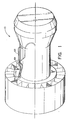
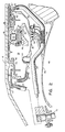
- Figs. 1 & 2 showing a typical fan jet engine generally indicated by reference numeral 10, having a fan section, compressor section, combustor section, turbine section and exhaust section.
- reference numeral 10 For the sake of simplicity and convenience, the details of a suitable gas turbine engine is omitted herefrom but reference should be made to the JT-9D engine manufactured by Pratt & Whitney Aircraft of United Technologies Corporation, the assignee of this patent application.
- the power plant comprises a twin spool having axial flow compressor and turbine stages, where each set of stages of the compressor and turbines are interconnected by a shaft.
- the burner section is disposed between the compressor and turbine sections for developing sufficient energy to power the turbine and develop thrust for propulsion.
- the high pressure spool or gas generator (not shown) consists of shaft 12 suitably supported by roller bearings generally indicated by reference numeral 14. These bearings are well known and consists of an inner ring 16 mounted adjacent shaft 12, an outer ring 18, a plurality of rollers 20 and cage 22 and, in this instant, are surrounded by fluid damper 26.
- the bearing is encapsulated in the cavity or compartment 38 defined by housing 36 surrounding the shaft 12.
- the ends of the compartment 38 are sealed by suitable carbon seals 40 and 40' which are spring loaded (not shown) against the face of the seal plates 42 and 42' respectively.
- the construction of the carbon seals are well known and an example of a suitable construction is shown in U.S. Patent No. 2,992,842 granted to Shevchenko et al on July 18, 1961 also assigned to the same assignee as this patent application and incorporated herein by reference.
- the cavity 38 is continuously subjected to the flow of oil which serves to lubricate and cool the bearings which oil is returned through return line 44 mounted on the bottom of housing 36.
- the bearing housing is supported to the diffuser case partially shown as reference numeral 46 which surrounds the burner line (not shown) and defines therewith a cavity 48 that surrounds and shrouds the burner liner. Since the bearing compartment is radially disposed relative to the combustor and is exposed to the already heated compressor discharge air surrounding the bearing compartment, under certain operating conditions this location of the engine has the propensity of becoming extremely hot.
- One method of insulating the bearing cavity 38 from this excessive heat is by wrapping an insulating blanket 50 of suitable material (partially shown) around the housing 36.
- a buffer zone is disposed at the inside diameter of the carbon seals.
- This buffer zone is supplied with a cool,high pressure air bled from the compressor. The temperature of this air is cooler and at a higher pressure than the ambient air surrounding the bearing compartment. While this system prevents hot air from entering the bearing compartment under normal operating conditions, in the event of an inadvertent leakage of the seal, the hotter ambient air is likewise prevented from entering into the bearing compartment, without first being mixed with buffer air.
- the cooler pressurized air is introduced at the inner diameter of the carbon seal in the annulus 48 and 48' by pipes 60 and 62 to fill the spaces between the shaft 12, seal support structure 52 up to the seal plate 42 on the left hand side of the bearing 14 and between the sleeve 56, seal support 52' up to the seal plate 42', on the right hand side of bearing 14. While only a single feed line is shown on either side of the bearing, each side may carry more than one pipe, and two pipes spaced 180 0 apart are preferred in this embodiment.
- Pipes 60 and 62 are concentrically mounted in outer tubes 66 & 64, respectively, which serve to insulate the inner pipe and maintain the air flowing to the buffer zone at a proper temperature level.
- the cooler pressurized air as can be seen from Fig. 1, is bled from a suitable station in the compressor section, routed outside of the engine via line 68, through the fan heat exchanger 70 and returned internally via line 69 to the pipes 60 and 62 through manifold 72, (Fig. 2).
- the air feeding the buffer zone 48 and 48' which virtually is an annular chamber surrounding the shaft that feeds the leakage path across the carbon seals 40 and 40' is introduced at a point that is remote from the carbon seals.
- cavities 48 and 48' are both open ended chambers where buffer air can flow out through the carbon seal or through the gaps 80 and 80'.
- some portion of this air will always flow toward the carbon seal while the remaining portion of this air flows out of the buffer zone 48 and 48' through the gaps 80 and 80'.
- the amount of air required by a carbon seal is minimal relative to that supplied to the buffer zone during normal operation. The excess flow flows out gap 80.
- Fig. 3 exemplifies another embodiment of this invention and like-reference numerals refer to like parts.
- the encapsulated bearing compartment is enclosed on virtually both the left and right hand sides with sheet metal sheaths 86 and 86' spaced therefrom to define annular chambers 88 and 88'.
- a second left and right hand side sheath 90 and 90' encapsulate the entire unit and is spaced from the inner sheath 86 and 86' to define annular spaces 92 and 92'.
- the outer annular spaces 92 and 92' are dead ended and provide a dead air space that serve as an insulating blanket for the bearing compartment. This minimizes heat transfer from the hotter air surrounding the compartment to the oil in the bearing compartment.
- the system in Fig. 3 receives the higher pressure, cooler air from the heat exchanger and is fed into conduit 96 that serves as a manifold to feed the annular spaces 88 and 88' which in turn feeds the buffer zones 48 and 48'.
- the buffer zones are open-ended and do not require closely held labyrinth seals to contain the buffer air and prevent hot environmental air pollution in close proximity of the carbon seals.
- the system can be satisfied with the proper pressure, and temperature air.
- the buffer air temperature is colder for a given pressure level than air directly drawn off the compressor system.
Landscapes
- Engineering & Computer Science (AREA)
- General Engineering & Computer Science (AREA)
- Mechanical Engineering (AREA)
- Chemical & Material Sciences (AREA)
- Combustion & Propulsion (AREA)
- Turbine Rotor Nozzle Sealing (AREA)
- Engine Equipment That Uses Special Cycles (AREA)
- Separation By Low-Temperature Treatments (AREA)
Applications Claiming Priority (2)
| Application Number | Priority Date | Filing Date | Title |
|---|---|---|---|
| US49963383A | 1983-05-31 | 1983-05-31 | |
| US499633 | 1983-05-31 |
Publications (3)
| Publication Number | Publication Date |
|---|---|
| EP0127562A2 true EP0127562A2 (de) | 1984-12-05 |
| EP0127562A3 EP0127562A3 (en) | 1987-04-08 |
| EP0127562B1 EP0127562B1 (de) | 1990-08-08 |
Family
ID=23986059
Family Applications (1)
| Application Number | Title | Priority Date | Filing Date |
|---|---|---|---|
| EP84630070A Expired - Lifetime EP0127562B1 (de) | 1983-05-31 | 1984-04-27 | Schutzsystem für Lagerkammer |
Country Status (3)
| Country | Link |
|---|---|
| EP (1) | EP0127562B1 (de) |
| JP (1) | JPS59226236A (de) |
| DE (2) | DE127562T1 (de) |
Cited By (8)
| Publication number | Priority date | Publication date | Assignee | Title |
|---|---|---|---|---|
| WO1995031632A1 (en) * | 1994-05-17 | 1995-11-23 | Pratt & Whitney Canada Inc. | Annular bearing compartment |
| WO2001027444A1 (en) * | 1999-10-12 | 2001-04-19 | Alm Development, Inc. | Bearing housing for a turbomachine |
| FR2961258A1 (fr) * | 2010-06-15 | 2011-12-16 | Snecma | Dispositif de guidage et d'etancheite a joint carbone et a palier lisse integre pour une turbomachine |
| US8689561B2 (en) | 2009-09-13 | 2014-04-08 | Donald W. Kendrick | Vortex premixer for combustion apparatus |
| EP2809907A4 (de) * | 2012-01-31 | 2015-10-28 | United Technologies Corp | Puffersystem für einen gasturbinenmotor |
| WO2019162600A1 (fr) * | 2018-02-23 | 2019-08-29 | Safran Aircraft Engines | Turbomachine comportant un echangeur de chaleur constitue d'au moins une plateforme inter aubes |
| CN114542205A (zh) * | 2022-02-11 | 2022-05-27 | 中国航发沈阳发动机研究所 | 一种高马赫航空发动机耐高温高压轴承腔结构 |
| WO2026041333A1 (en) * | 2024-08-23 | 2026-02-26 | Siemens Energy Global GmbH & Co. KG | Fluid transport pipe with high thermal resistance |
Families Citing this family (3)
| Publication number | Priority date | Publication date | Assignee | Title |
|---|---|---|---|---|
| US6799112B1 (en) * | 2003-10-03 | 2004-09-28 | General Electric Company | Methods and apparatus for operating gas turbine engines |
| FR2877036B1 (fr) * | 2004-10-27 | 2006-12-22 | Snecma Moteurs Sa | Dispositif de lubrification d'un composant dans une turbomachine |
| US10167734B2 (en) | 2012-09-27 | 2019-01-01 | United Technologies Corporation | Buffer airflow to bearing compartment |
Family Cites Families (13)
| Publication number | Priority date | Publication date | Assignee | Title |
|---|---|---|---|---|
| CH266730A (de) * | 1948-08-11 | 1950-02-15 | Siegfried Keller & Co | Vorrichtung zur Vermeidung von Schmiermittelverlusten bei hochtourigen Turbomaschinen mit fliegender Läuferanordnung. |
| GB702931A (en) * | 1951-04-18 | 1954-01-27 | Bristol Aeroplane Co Ltd | Improvements in or relating to rotary machines comprising fluid compressing means |
| US2791090A (en) * | 1952-08-05 | 1957-05-07 | Bristol Aeroplane Co Ltd | Improved cooling and lubricating arrangement for bearings of a gas turbine engine |
| US2992842A (en) * | 1958-04-21 | 1961-07-18 | United Aircraft Corp | Oil scrubbed face seal |
| FR1484834A (fr) * | 1966-05-09 | 1967-06-16 | Bristol Siddeley Engines Ltd | Perfectionnements apportés aux moteurs comportant une turbine à gaz |
| US3768921A (en) * | 1972-02-24 | 1973-10-30 | Aircraft Corp | Chamber pressure control using free vortex flow |
| CH557952A (de) * | 1972-11-08 | 1975-01-15 | Bbc Sulzer Turbomaschinen | Gasturbinenanlage. |
| GB1421540A (en) * | 1972-11-24 | 1976-01-21 | Rolls Royce | Shaft bearing assemblies |
| US3844110A (en) * | 1973-02-26 | 1974-10-29 | Gen Electric | Gas turbine engine internal lubricant sump venting and pressurization system |
| US4156342A (en) * | 1976-06-11 | 1979-05-29 | Westinghouse Canada Limited | Cooling apparatus for a bearing in a gas turbine |
| US4369016A (en) * | 1979-12-21 | 1983-01-18 | United Technologies Corporation | Turbine intermediate case |
| US4337983A (en) * | 1980-12-11 | 1982-07-06 | United Technologies Corporation | Viscous damper |
| US4385788A (en) * | 1981-06-26 | 1983-05-31 | United Technologies Corporation | Roller bearing and construction thereof |
-
1984
- 1984-04-27 JP JP59086082A patent/JPS59226236A/ja active Granted
- 1984-04-27 EP EP84630070A patent/EP0127562B1/de not_active Expired - Lifetime
- 1984-04-27 DE DE198484630070T patent/DE127562T1/de active Pending
- 1984-04-27 DE DE8484630070T patent/DE3482915D1/de not_active Expired - Lifetime
Cited By (17)
| Publication number | Priority date | Publication date | Assignee | Title |
|---|---|---|---|---|
| WO1995031632A1 (en) * | 1994-05-17 | 1995-11-23 | Pratt & Whitney Canada Inc. | Annular bearing compartment |
| WO2001027444A1 (en) * | 1999-10-12 | 2001-04-19 | Alm Development, Inc. | Bearing housing for a turbomachine |
| US8689561B2 (en) | 2009-09-13 | 2014-04-08 | Donald W. Kendrick | Vortex premixer for combustion apparatus |
| US8689562B2 (en) | 2009-09-13 | 2014-04-08 | Donald W. Kendrick | Combustion cavity layouts for fuel staging in trapped vortex combustors |
| FR2961258A1 (fr) * | 2010-06-15 | 2011-12-16 | Snecma | Dispositif de guidage et d'etancheite a joint carbone et a palier lisse integre pour une turbomachine |
| WO2011157937A1 (fr) * | 2010-06-15 | 2011-12-22 | Snecma | Dispositif de guidage et d'etancheite a joint carbone et a palier lisse integre pour une turbomachine |
| US8920034B2 (en) | 2010-06-15 | 2014-12-30 | Snecma | Guide and sealing device for a turbine engine, the device having a carbon gasket and an integrated smooth bearing |
| US9879602B2 (en) | 2012-01-31 | 2018-01-30 | United Technologies Corporation | Compressed air bleed supply for buffer system |
| EP2809907A4 (de) * | 2012-01-31 | 2015-10-28 | United Technologies Corp | Puffersystem für einen gasturbinenmotor |
| US10731563B2 (en) | 2012-01-31 | 2020-08-04 | Raytheon Technologies Corporation | Compressed air bleed supply for buffer system |
| WO2019162600A1 (fr) * | 2018-02-23 | 2019-08-29 | Safran Aircraft Engines | Turbomachine comportant un echangeur de chaleur constitue d'au moins une plateforme inter aubes |
| FR3078369A1 (fr) * | 2018-02-23 | 2019-08-30 | Safran Aircraft Engines | Turbomachine comportant un echangeur de chaleur constitue d'au moins une plateforme inter aubes |
| CN111742127A (zh) * | 2018-02-23 | 2020-10-02 | 赛峰飞机发动机公司 | 包括由叶片之间的至少一个平台组成的热交换器的涡轮发动机 |
| US12180912B2 (en) | 2018-02-23 | 2024-12-31 | Safran Aircraft Engines | Turbine engine comprising a heat exchanger consisting of at least one deck between vanes |
| CN114542205A (zh) * | 2022-02-11 | 2022-05-27 | 中国航发沈阳发动机研究所 | 一种高马赫航空发动机耐高温高压轴承腔结构 |
| CN114542205B (zh) * | 2022-02-11 | 2022-11-22 | 中国航发沈阳发动机研究所 | 一种高马赫航空发动机耐高温高压轴承腔结构 |
| WO2026041333A1 (en) * | 2024-08-23 | 2026-02-26 | Siemens Energy Global GmbH & Co. KG | Fluid transport pipe with high thermal resistance |
Also Published As
| Publication number | Publication date |
|---|---|
| DE3482915D1 (de) | 1990-09-13 |
| JPH0475373B2 (de) | 1992-11-30 |
| DE127562T1 (de) | 1985-08-14 |
| JPS59226236A (ja) | 1984-12-19 |
| EP0127562A3 (en) | 1987-04-08 |
| EP0127562B1 (de) | 1990-08-08 |
Similar Documents
| Publication | Publication Date | Title |
|---|---|---|
| US4709545A (en) | Bearing compartment protection system | |
| US5622438A (en) | Fire resistant bearing compartment cover | |
| EP1307672B1 (de) | Pufferdichtungsanordnung für ölwanne | |
| US6438938B1 (en) | Bearing compartment self cooling vent system | |
| US3312448A (en) | Seal arrangement for preventing leakage of lubricant in gas turbine engines | |
| US7383686B2 (en) | Secondary flow, high pressure turbine module cooling air system for recuperated gas turbine engines | |
| US5195868A (en) | Heat shield for a compressor/stator structure | |
| EP0760053B1 (de) | Ringförmiges lagergehäuse | |
| US7269957B2 (en) | Combustion liner having improved cooling and sealing | |
| US9810097B2 (en) | Corrugated mid-turbine frame thermal radiation shield | |
| EP0244342A2 (de) | Bewegliche Abdichtung für eine Ringbrennkammer | |
| EP0127562B1 (de) | Schutzsystem für Lagerkammer | |
| EP3904731B1 (de) | Poröses dichtungselement mit internem fluidkanal | |
| GB2229496A (en) | Cooling gas turbine engine component or region | |
| US20230304444A1 (en) | Buffer fluid delivery system and method for a shaft seal of a gas turbine engine | |
| US7435052B2 (en) | Shaft oil purge system | |
| JPS6124529B2 (de) | ||
| US10047623B2 (en) | Compliant seal assembly and method of operating | |
| EP0127563B1 (de) | Schutzsystem für Lagerkammer | |
| US4460313A (en) | Heat shield for radial gas turbine | |
| US11549396B2 (en) | Mid-turbine frame for gas turbine engine | |
| EP3904732B1 (de) | Rotationsgerätdichtungselement mit innerem fluidkanal | |
| US12037949B2 (en) | Bearing-supported shaft assembly | |
| US11280208B2 (en) | Labyrinth seal assembly | |
| RU2307947C2 (ru) | Газотурбинный двигатель |
Legal Events
| Date | Code | Title | Description |
|---|---|---|---|
| PUAI | Public reference made under article 153(3) epc to a published international application that has entered the european phase |
Free format text: ORIGINAL CODE: 0009012 |
|
| AK | Designated contracting states |
Designated state(s): DE FR GB |
|
| EL | Fr: translation of claims filed | ||
| DET | De: translation of patent claims | ||
| PUAL | Search report despatched |
Free format text: ORIGINAL CODE: 0009013 |
|
| AK | Designated contracting states |
Kind code of ref document: A3 Designated state(s): DE FR GB |
|
| 17P | Request for examination filed |
Effective date: 19870928 |
|
| 17Q | First examination report despatched |
Effective date: 19881107 |
|
| GRAA | (expected) grant |
Free format text: ORIGINAL CODE: 0009210 |
|
| AK | Designated contracting states |
Kind code of ref document: B1 Designated state(s): DE FR GB |
|
| ET | Fr: translation filed | ||
| REF | Corresponds to: |
Ref document number: 3482915 Country of ref document: DE Date of ref document: 19900913 |
|
| PLBE | No opposition filed within time limit |
Free format text: ORIGINAL CODE: 0009261 |
|
| STAA | Information on the status of an ep patent application or granted ep patent |
Free format text: STATUS: NO OPPOSITION FILED WITHIN TIME LIMIT |
|
| 26N | No opposition filed | ||
| PGFP | Annual fee paid to national office [announced via postgrant information from national office to epo] |
Ref country code: GB Payment date: 20010323 Year of fee payment: 18 |
|
| PGFP | Annual fee paid to national office [announced via postgrant information from national office to epo] |
Ref country code: FR Payment date: 20010329 Year of fee payment: 18 |
|
| PGFP | Annual fee paid to national office [announced via postgrant information from national office to epo] |
Ref country code: DE Payment date: 20010331 Year of fee payment: 18 |
|
| REG | Reference to a national code |
Ref country code: GB Ref legal event code: IF02 |
|
| PG25 | Lapsed in a contracting state [announced via postgrant information from national office to epo] |
Ref country code: GB Free format text: LAPSE BECAUSE OF NON-PAYMENT OF DUE FEES Effective date: 20020427 |
|
| PG25 | Lapsed in a contracting state [announced via postgrant information from national office to epo] |
Ref country code: DE Free format text: LAPSE BECAUSE OF NON-PAYMENT OF DUE FEES Effective date: 20021101 |
|
| GBPC | Gb: european patent ceased through non-payment of renewal fee |
Effective date: 20020427 |
|
| PG25 | Lapsed in a contracting state [announced via postgrant information from national office to epo] |
Ref country code: FR Free format text: LAPSE BECAUSE OF NON-PAYMENT OF DUE FEES Effective date: 20021231 |
|
| REG | Reference to a national code |
Ref country code: FR Ref legal event code: ST |