EP0127896A2 - Digital gesteuerte Gleichrichteranordnung zum Antrieb eines Motors - Google Patents
Digital gesteuerte Gleichrichteranordnung zum Antrieb eines Motors Download PDFInfo
- Publication number
- EP0127896A2 EP0127896A2 EP84106313A EP84106313A EP0127896A2 EP 0127896 A2 EP0127896 A2 EP 0127896A2 EP 84106313 A EP84106313 A EP 84106313A EP 84106313 A EP84106313 A EP 84106313A EP 0127896 A2 EP0127896 A2 EP 0127896A2
- Authority
- EP
- European Patent Office
- Prior art keywords
- current
- converters
- output
- motor
- controller
- Prior art date
- Legal status (The legal status is an assumption and is not a legal conclusion. Google has not performed a legal analysis and makes no representation as to the accuracy of the status listed.)
- Withdrawn
Links
Images

Classifications
-
- H—ELECTRICITY
- H02—GENERATION; CONVERSION OR DISTRIBUTION OF ELECTRIC POWER
- H02M—APPARATUS FOR CONVERSION BETWEEN AC AND AC, BETWEEN AC AND DC, OR BETWEEN DC AND DC, AND FOR USE WITH MAINS OR SIMILAR POWER SUPPLY SYSTEMS; CONVERSION OF DC OR AC INPUT POWER INTO SURGE OUTPUT POWER; CONTROL OR REGULATION THEREOF
- H02M7/00—Conversion of AC power input into DC power output; Conversion of DC power input into AC power output
- H02M7/02—Conversion of AC power input into DC power output without possibility of reversal
- H02M7/04—Conversion of AC power input into DC power output without possibility of reversal by static converters
- H02M7/12—Conversion of AC power input into DC power output without possibility of reversal by static converters using discharge tubes with control electrode or semiconductor devices with control electrode
- H02M7/145—Conversion of AC power input into DC power output without possibility of reversal by static converters using discharge tubes with control electrode or semiconductor devices with control electrode using devices of a thyratron or thyristor type requiring extinguishing means
-
- H—ELECTRICITY
- H02—GENERATION; CONVERSION OR DISTRIBUTION OF ELECTRIC POWER
- H02P—CONTROL OR REGULATION OF ELECTRIC MOTORS, ELECTRIC GENERATORS OR DYNAMO-ELECTRIC CONVERTERS; CONTROLLING TRANSFORMERS, REACTORS OR CHOKE COILS
- H02P7/00—Arrangements for regulating or controlling the speed or torque of electric DC motors
- H02P7/06—Arrangements for regulating or controlling the speed or torque of electric DC motors for regulating or controlling an individual DC dynamo-electric motor by varying field or armature current
- H02P7/18—Arrangements for regulating or controlling the speed or torque of electric DC motors for regulating or controlling an individual DC dynamo-electric motor by varying field or armature current by master control with auxiliary power
- H02P7/24—Arrangements for regulating or controlling the speed or torque of electric DC motors for regulating or controlling an individual DC dynamo-electric motor by varying field or armature current by master control with auxiliary power using discharge tubes or semiconductor devices
- H02P7/28—Arrangements for regulating or controlling the speed or torque of electric DC motors for regulating or controlling an individual DC dynamo-electric motor by varying field or armature current by master control with auxiliary power using discharge tubes or semiconductor devices using semiconductor devices
- H02P7/285—Arrangements for regulating or controlling the speed or torque of electric DC motors for regulating or controlling an individual DC dynamo-electric motor by varying field or armature current by master control with auxiliary power using discharge tubes or semiconductor devices using semiconductor devices controlling armature supply only
- H02P7/2855—Arrangements for regulating or controlling the speed or torque of electric DC motors for regulating or controlling an individual DC dynamo-electric motor by varying field or armature current by master control with auxiliary power using discharge tubes or semiconductor devices using semiconductor devices controlling armature supply only whereby the speed is regulated by measuring the motor speed and comparing it with a given physical value
-
- H—ELECTRICITY
- H02—GENERATION; CONVERSION OR DISTRIBUTION OF ELECTRIC POWER
- H02P—CONTROL OR REGULATION OF ELECTRIC MOTORS, ELECTRIC GENERATORS OR DYNAMO-ELECTRIC CONVERTERS; CONTROLLING TRANSFORMERS, REACTORS OR CHOKE COILS
- H02P7/00—Arrangements for regulating or controlling the speed or torque of electric DC motors
- H02P7/06—Arrangements for regulating or controlling the speed or torque of electric DC motors for regulating or controlling an individual DC dynamo-electric motor by varying field or armature current
- H02P7/18—Arrangements for regulating or controlling the speed or torque of electric DC motors for regulating or controlling an individual DC dynamo-electric motor by varying field or armature current by master control with auxiliary power
- H02P7/24—Arrangements for regulating or controlling the speed or torque of electric DC motors for regulating or controlling an individual DC dynamo-electric motor by varying field or armature current by master control with auxiliary power using discharge tubes or semiconductor devices
- H02P7/28—Arrangements for regulating or controlling the speed or torque of electric DC motors for regulating or controlling an individual DC dynamo-electric motor by varying field or armature current by master control with auxiliary power using discharge tubes or semiconductor devices using semiconductor devices
- H02P7/281—Arrangements for regulating or controlling the speed or torque of electric DC motors for regulating or controlling an individual DC dynamo-electric motor by varying field or armature current by master control with auxiliary power using discharge tubes or semiconductor devices using semiconductor devices the DC motor being operated in four quadrants
- H02P7/2815—Arrangements for regulating or controlling the speed or torque of electric DC motors for regulating or controlling an individual DC dynamo-electric motor by varying field or armature current by master control with auxiliary power using discharge tubes or semiconductor devices using semiconductor devices the DC motor being operated in four quadrants whereby the speed is regulated by measuring the motor speed and comparing it with a given physical value
-
- H—ELECTRICITY
- H02—GENERATION; CONVERSION OR DISTRIBUTION OF ELECTRIC POWER
- H02P—CONTROL OR REGULATION OF ELECTRIC MOTORS, ELECTRIC GENERATORS OR DYNAMO-ELECTRIC CONVERTERS; CONTROLLING TRANSFORMERS, REACTORS OR CHOKE COILS
- H02P2201/00—Indexing scheme relating to controlling arrangements characterised by the converter used
- H02P2201/13—DC-link of current link type, e.g. typically for thyristor bridges, having an inductor in series with rectifier
-
- Y—GENERAL TAGGING OF NEW TECHNOLOGICAL DEVELOPMENTS; GENERAL TAGGING OF CROSS-SECTIONAL TECHNOLOGIES SPANNING OVER SEVERAL SECTIONS OF THE IPC; TECHNICAL SUBJECTS COVERED BY FORMER USPC CROSS-REFERENCE ART COLLECTIONS [XRACs] AND DIGESTS
- Y10—TECHNICAL SUBJECTS COVERED BY FORMER USPC
- Y10S—TECHNICAL SUBJECTS COVERED BY FORMER USPC CROSS-REFERENCE ART COLLECTIONS [XRACs] AND DIGESTS
- Y10S388/00—Electricity: motor control systems
- Y10S388/907—Specific control circuit element or device
- Y10S388/91—Operational/differential amplifier
-
- Y—GENERAL TAGGING OF NEW TECHNOLOGICAL DEVELOPMENTS; GENERAL TAGGING OF CROSS-SECTIONAL TECHNOLOGIES SPANNING OVER SEVERAL SECTIONS OF THE IPC; TECHNICAL SUBJECTS COVERED BY FORMER USPC CROSS-REFERENCE ART COLLECTIONS [XRACs] AND DIGESTS
- Y10—TECHNICAL SUBJECTS COVERED BY FORMER USPC
- Y10S—TECHNICAL SUBJECTS COVERED BY FORMER USPC CROSS-REFERENCE ART COLLECTIONS [XRACs] AND DIGESTS
- Y10S388/00—Electricity: motor control systems
- Y10S388/907—Specific control circuit element or device
- Y10S388/921—Timer or time delay means
Definitions
- the present invention relates to a digitally controlled rectifying system used for driving an electric motor.
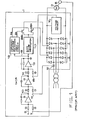
- Fig. 1 Conventionally, there have been used rectifying systems of the analog control type for driving electric motors as shown in Fig. 1.
- the system arrangement of Fig. 1 includes a motor driving rectifying system 1, a d.c. motor 2, a forward converter 3 made up of a 3-phase thyristor bridge, and a reverse converter 4 also made up of a 3-phase thyristor bridge.
- the control system is of a feedback system comprising a speed control loop and two minor loops of the current and voltage feedback.
- the rectifying system 1 incorporates a speed controller 5 made of an operational amplifier configured to provide a proportional and integral functions, a terminal 6 for receiving a speed command signal, a terminal 7 for receiving a feedback speed signal which is produced uninterruptedly by a pilot generator 8 associated with the motor 2, a current controller 9 made up of an operational amplifier configured to provide an integral function, an output terminal 10 of the speed controller 5 which provides the current command signal, a terminal 11 for receiving a feedback current signal which is produced in response to the input a.c. current detected by an a.c.
- ACCT current transformer
- voltage controller 13 made up of an operational amplifier configured to provide a first-order time lag function
- an output terminal 14 of the current controller 9 which provides a voltage command signal
- a terminal 15 for receiving a feedback voltage signal which is produced in response to the d.c.
- a gate pulse generator 17 incorporating a cos -1 function for providing a linearized output voltage for a phase command signal with a bias voltage Eb being applied thereto in order to stabilize the gate switching operation for the forward and reverse converters 3 and 4 as will be explained later
- a forward/reverse switching logic circuit 18 for selecting the output of the gate pulse signal (a) and (b) for the forward and reverse converters 3 and 4, and gate pulse switches 28a and 28b for conducting gate pulses to the forward and reverse converters 3 and 4.
- Symbols @ and ⁇ shown at the inputs and outputs of the speed, current and voltage controllers 5, 9 and 13 represent the polarity of respective control signals when the motor 2 rotates in a forward direction.
- F ig. 2 is a graph used to explain the correlation between the input signal of the gate pulse generator 17, i.e., the output signal 19 of the voltage controller 13, and the d.c. output voltage.
- the solid line shown by A represents the characteristics when the load current flows continuously
- the shaded portion shown by B represents the characteristics when the load current flows intermittently
- the dashed lines shown by C represent the state in which the load current is completely cut off.
- the provision of the dead band is to prevent the forward and reverse converters 3 and 4 from becoming conductive simultaneously, and for this purpose the output characteristics of both converters are biased by a predetermined amount of +Eb volts with respect to the output signal of the voltage controller 13.
- the voltage level shown by Ec in the graph represents the counter electromotive force produced by the motor 2 when it rotates in the forward direction.
- the speed controller 5 When the speed controller 5 is given a deceleration command 6, its output signal 10 decreases from a positive value and then enters the negative region. Since the current controller 9 has an integral property, its negative output signal 14 when evaluated as an absolute value starts decreasing at a rate proportional to the product of the reciprocal of the integrating time constant and the input error signal.
- the output signal 19 of the voltage controller 13 has decreased down to the input signal level V 1 , the load current becomes a complete zero, causing the output signal 14 of the current controller 9 to vary solely in response to the current command signal 10.
- the switching logic circuit 18 When the voltage controller 13 has reversed the polarity of the output signal from positive to negative, the switching logic circuit 18 operates on the gate pulse signal by its output signals Sa and Sb to switch from the forward converter 3 to the reverse converter 4.
- the output signal 19 When the output signal 19 has reached the input signal level -V 2 , the current starts flowing through the reverse converter 4, bringing the motor 2 in a regenerative operating mode, and the motor speed starts falling.
- the mean time when the output signal 19 varies from the input level V 1 to -V 2 no load current flows in the motor 2, and it is an idle time for the control system.
- This idle time cannot be nullified due to the bias Eb provided for the output of the voltage controller 13 in order to prevent a short-circuit of the forward and reverse converters 3 and 4, and to make the matter worse the idle time is significantly affected by the gain of the current controller 9 and voltage controller 13.
- Another object of the present invention is to provide a high response and high controllability rectifying system which considerably reduces the gate switching time and, thus, eliminates the time lag of the control system.
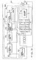
- Fig. 3 shows in block-form the microprocessor based motor driving rectifying system embodying the present invention.
- a section 20 defined by the dot-and-dash line is a motor driving rectifying system
- a minor section 30 defined by the dots-and-dash line is a microprocessor based controller.
- Reference number 23 denotes a motor speed measuring unit which counts pulses from a pulse generator 22 coupled to the drive shaft of the motor 2 and provides a digital value in correspondence to the rotational speed of the motor 2.
- the controller 30 has a speed command input terminal 21, a block 24 which corresponds to the speed controller 5 of Fig. 1, and another block 25 which corresponds to the current controller 9 of Fig. 1. Both of the speed controller 24 and current controller 25 perform computation for the proportional and integral control.
- the output of the current controller 25 is conducted through a high-speed switching logic circuit 27, as will be described later, to a gate pulse generator 26 which is constituted by discrete digital components.
- the gate pulse generator 26 incorporates a cos -1 function generator.
- the gate pulse generator 26 differs from the pulse generator 17 (Fig. 1) in the conventional system in that the input is not biased.
- Fig. 4 shows the waveform of the output voltage Ed of the rectifying system 20 and the counter electromotive force Ec of the motor 2 when the load current Id flows continuously.
- Fig. 5 shows the waveform of Ed, indicating that the load current Id becomes zero when the peak value of the output voltage Ed is equal to the counter electromotive force Ec.
- Es is the effective input line voltage.
- the high-speed gate switching logic circuit 27 when it does not perform gate switching, passes the proportional and integral output from the current controller 25 directly as a firing phase angle command signal to the gate pulse generator 26.
- the logic circuit 27 shifts the firing phase angle a by 180° so that the load current is forced to become zero.
- the logic circuit 27 Upon detection of the zero load current Id, the logic circuit 27 reverses the states of the gate pulse switches 28a and 28b, and at the same time shifts the firing angle command signal so that the firing phase angle a Reefs the equation (1).
- the integral part of the output from the current controller 25 is made equal to the firing angle command signal as obtained in the above process.
- the firing phase angle a at this time is expressed by the following equation.
- Ec is the counter electromotive force of the motor 2 detected by the voltage sensor 16 when the load current Id becomes zero. Since the firing phase angle a following the gate switching operation has a critical value at which the load current is kept zero, the load current flows progressively as the firing phase angle a advances.
- the firing phase angle a is shifted by 180° when the gate control for the forward and reverse converters are switched so that the load current is forced to become zero, and after the gate switching, the firing phase angle is shifted to a phase angle at which the current just starts flowing.
Landscapes
- Engineering & Computer Science (AREA)
- Power Engineering (AREA)
- Control Of Direct Current Motors (AREA)
- Motor And Converter Starters (AREA)
- Control Of Electric Motors In General (AREA)
- Stopping Of Electric Motors (AREA)
- Control Of Ac Motors In General (AREA)
Applications Claiming Priority (2)
| Application Number | Priority Date | Filing Date | Title |
|---|---|---|---|
| JP99676/83U | 1983-06-03 | ||
| JP58099676A JPS59226681A (ja) | 1983-06-03 | 1983-06-03 | デイジタル制御方式の電動機駆動用整流装置 |
Publications (2)
| Publication Number | Publication Date |
|---|---|
| EP0127896A2 true EP0127896A2 (de) | 1984-12-12 |
| EP0127896A3 EP0127896A3 (de) | 1986-04-30 |
Family
ID=14253632
Family Applications (1)
| Application Number | Title | Priority Date | Filing Date |
|---|---|---|---|
| EP84106313A Withdrawn EP0127896A3 (de) | 1983-06-03 | 1984-06-01 | Digital gesteuerte Gleichrichteranordnung zum Antrieb eines Motors |
Country Status (4)
| Country | Link |
|---|---|
| US (1) | US4567408A (de) |
| EP (1) | EP0127896A3 (de) |
| JP (1) | JPS59226681A (de) |
| KR (1) | KR890001901B1 (de) |
Cited By (1)
| Publication number | Priority date | Publication date | Assignee | Title |
|---|---|---|---|---|
| CN102494599A (zh) * | 2011-11-01 | 2012-06-13 | 中国科学院国家天文台南京天文光学技术研究所 | 大口径毫米波/亚毫米波望远镜控制系统位置检测方法 |
Families Citing this family (5)
| Publication number | Priority date | Publication date | Assignee | Title |
|---|---|---|---|---|
| US4658192A (en) * | 1986-01-31 | 1987-04-14 | General Electric Company | Programmable deadband current regulator |
| US5053688A (en) * | 1989-03-07 | 1991-10-01 | Sundstrand Corporation | Feedback circuit for eliminating DC offset in drive current of an AC motor |
| JPH02239782A (ja) * | 1989-03-14 | 1990-09-21 | Canon Electron Inc | 光量制御装置 |
| US6385066B1 (en) | 2000-11-01 | 2002-05-07 | General Electric Corporation | Method and system for detecting a zero current level in a line commutated converter |
| JP4449882B2 (ja) * | 2005-10-14 | 2010-04-14 | 株式会社デンソー | 車両用発電制御装置 |
Family Cites Families (10)
| Publication number | Priority date | Publication date | Assignee | Title |
|---|---|---|---|---|
| US3413534A (en) * | 1966-03-14 | 1968-11-26 | Westinghouse Electric Corp | Non-regenerating dc motor regulating circuit having improved stability |
| CA862870A (en) * | 1967-02-13 | 1971-02-02 | Westinghouse Electric Corporation | Dual converter electrical drive system |
| US3590350A (en) * | 1968-08-30 | 1971-06-29 | Westinghouse Electric Corp | Motor control for skip hoist drive systems and the like |
| US3617844A (en) * | 1969-05-21 | 1971-11-02 | Eaton Yale & Towne | Controlled-velocity drive |
| US4263557A (en) * | 1976-11-22 | 1981-04-21 | General Electric Company | Power converter control |
| US4090116A (en) * | 1976-12-10 | 1978-05-16 | General Electric Company | Closed loop digital control system and method for motor control |
| JPS6022597B2 (ja) * | 1977-09-08 | 1985-06-03 | ファナック株式会社 | 直流モ−タの駆動装置 |
| US4277825A (en) * | 1979-07-27 | 1981-07-07 | Westinghouse Electric Corp. | Converter apparatus |
| JPS5778385A (en) * | 1980-10-30 | 1982-05-17 | Fanuc Ltd | Digital control system for dc motor |
| JPS57207901A (en) * | 1981-06-17 | 1982-12-20 | Mitsubishi Electric Corp | Digital controlling device |
-
1983
- 1983-06-03 JP JP58099676A patent/JPS59226681A/ja active Granted
-
1984
- 1984-04-21 KR KR1019840002104A patent/KR890001901B1/ko not_active Expired
- 1984-06-01 EP EP84106313A patent/EP0127896A3/de not_active Withdrawn
- 1984-12-28 US US06/687,025 patent/US4567408A/en not_active Expired - Fee Related
Cited By (1)
| Publication number | Priority date | Publication date | Assignee | Title |
|---|---|---|---|---|
| CN102494599A (zh) * | 2011-11-01 | 2012-06-13 | 中国科学院国家天文台南京天文光学技术研究所 | 大口径毫米波/亚毫米波望远镜控制系统位置检测方法 |
Also Published As
| Publication number | Publication date |
|---|---|
| EP0127896A3 (de) | 1986-04-30 |
| KR850000838A (ko) | 1985-03-09 |
| KR890001901B1 (ko) | 1989-05-30 |
| US4567408A (en) | 1986-01-28 |
| JPS59226681A (ja) | 1984-12-19 |
| JPH0113315B2 (de) | 1989-03-06 |
Similar Documents
| Publication | Publication Date | Title |
|---|---|---|
| US3783359A (en) | Brushless d. c. motor using hall generators for commutation | |
| US4546293A (en) | Motor control for a brushless DC motor | |
| US4322671A (en) | Induction motor drive apparatus | |
| EP0510527B1 (de) | Überwachungsschaltung für eine Vorrichtung zur Nachladung einer Batterie in einem Fahrzeug | |
| EP0144593B1 (de) | Steuersystem für einen Wechselrichter vom Spannungstyp | |
| US5093771A (en) | Inverter circuit and a method for controlling same | |
| US20020008489A1 (en) | Electric motor with two modes of power supply switching | |
| EP0127896A2 (de) | Digital gesteuerte Gleichrichteranordnung zum Antrieb eines Motors | |
| GB1468251A (en) | Braking-mode detection circuit for dc electric motors | |
| EP0012539B1 (de) | Schaltung zum Betrieb eines Gleichstrommotors mit Permanentmagneterregung | |
| EP0144161B1 (de) | Steuer- und Regelsystem für einen Wechselstrom-Motor | |
| US4703246A (en) | Control method and apparatus for synchronous motor | |
| US5126647A (en) | Pulse by pulse current limit and phase current monitor for a pulse width modulated inverter | |
| WO1994019865A1 (en) | Digital motor control system | |
| JPH01144385A (ja) | 同期機における電流崩壊の回避のための方法および回路装置 | |
| JPH0732593B2 (ja) | チョッパ制御装置 | |
| EP0279428B1 (de) | Regelsystem für einen elektrischen Motor | |
| SU824393A1 (ru) | Реверсивный тиристорный электроприводпОСТО ННОгО TOKA | |
| SU1272449A1 (ru) | Электропривод | |
| SU1056930A3 (ru) | Реверсивный электропривод посто нного тока | |
| JPS56101390A (en) | Constant output control system for thyristor motor | |
| SU1510061A2 (ru) | Частотно-управл емый электропривод | |
| WO1980001526A1 (en) | Control for direct-current motor with separately excited field | |
| SU1264294A1 (ru) | Электропривод переменного тока | |
| SU1658350A1 (ru) | Электропривод |
Legal Events
| Date | Code | Title | Description |
|---|---|---|---|
| PUAI | Public reference made under article 153(3) epc to a published international application that has entered the european phase |
Free format text: ORIGINAL CODE: 0009012 |
|
| AK | Designated contracting states |
Designated state(s): DE GB SE |
|
| PUAL | Search report despatched |
Free format text: ORIGINAL CODE: 0009013 |
|
| AK | Designated contracting states |
Kind code of ref document: A3 Designated state(s): DE GB SE |
|
| 17P | Request for examination filed |
Effective date: 19860925 |
|
| 17Q | First examination report despatched |
Effective date: 19880215 |
|
| STAA | Information on the status of an ep patent application or granted ep patent |
Free format text: STATUS: THE APPLICATION IS DEEMED TO BE WITHDRAWN |
|
| 18D | Application deemed to be withdrawn |
Effective date: 19880627 |
|
| RIN1 | Information on inventor provided before grant (corrected) |
Inventor name: MITSUHASHI, MASAMICHIC/O MITSUBISHI DENKI K.K. |