EP0127962B1 - Elektrischer Verbinder und Montur - Google Patents
Elektrischer Verbinder und Montur Download PDFInfo
- Publication number
- EP0127962B1 EP0127962B1 EP19840303131 EP84303131A EP0127962B1 EP 0127962 B1 EP0127962 B1 EP 0127962B1 EP 19840303131 EP19840303131 EP 19840303131 EP 84303131 A EP84303131 A EP 84303131A EP 0127962 B1 EP0127962 B1 EP 0127962B1
- Authority
- EP
- European Patent Office
- Prior art keywords
- locating means
- bus
- contact
- contact part
- sockets
- Prior art date
- Legal status (The legal status is an assumption and is not a legal conclusion. Google has not performed a legal analysis and makes no representation as to the accuracy of the status listed.)
- Expired
Links
- 239000004020 conductor Substances 0.000 claims description 41
- 210000003739 neck Anatomy 0.000 claims description 12
- 238000003491 array Methods 0.000 claims description 5
- 238000009413 insulation Methods 0.000 description 3
- 241000251468 Actinopterygii Species 0.000 description 2
- 239000000463 material Substances 0.000 description 2
- 230000000149 penetrating effect Effects 0.000 description 2
- 206010061307 Neck deformity Diseases 0.000 description 1
- 230000004075 alteration Effects 0.000 description 1
- 230000000295 complement effect Effects 0.000 description 1
- 230000000694 effects Effects 0.000 description 1
- 238000009429 electrical wiring Methods 0.000 description 1
- 238000003780 insertion Methods 0.000 description 1
- 230000037431 insertion Effects 0.000 description 1
- 238000004519 manufacturing process Methods 0.000 description 1
- 238000007567 mass-production technique Methods 0.000 description 1
- 239000002184 metal Substances 0.000 description 1
- 230000007935 neutral effect Effects 0.000 description 1
- 239000002243 precursor Substances 0.000 description 1
- 238000010079 rubber tapping Methods 0.000 description 1
Images


Classifications
-
- H—ELECTRICITY
- H01—ELECTRIC ELEMENTS
- H01R—ELECTRICALLY-CONDUCTIVE CONNECTIONS; STRUCTURAL ASSOCIATIONS OF A PLURALITY OF MUTUALLY-INSULATED ELECTRICAL CONNECTING ELEMENTS; COUPLING DEVICES; CURRENT COLLECTORS
- H01R12/00—Structural associations of a plurality of mutually-insulated electrical connecting elements, specially adapted for printed circuits, e.g. printed circuit boards [PCB], flat or ribbon cables, or like generally planar structures, e.g. terminal strips, terminal blocks; Coupling devices specially adapted for printed circuits, flat or ribbon cables, or like generally planar structures; Terminals specially adapted for contact with, or insertion into, printed circuits, flat or ribbon cables, or like generally planar structures
- H01R12/50—Fixed connections
- H01R12/59—Fixed connections for flexible printed circuits, flat or ribbon cables or like structures
- H01R12/65—Fixed connections for flexible printed circuits, flat or ribbon cables or like structures characterised by the terminal
- H01R12/67—Fixed connections for flexible printed circuits, flat or ribbon cables or like structures characterised by the terminal insulation penetrating terminals
-
- H—ELECTRICITY
- H01—ELECTRIC ELEMENTS
- H01R—ELECTRICALLY-CONDUCTIVE CONNECTIONS; STRUCTURAL ASSOCIATIONS OF A PLURALITY OF MUTUALLY-INSULATED ELECTRICAL CONNECTING ELEMENTS; COUPLING DEVICES; CURRENT COLLECTORS
- H01R25/00—Coupling parts adapted for simultaneous co-operation with two or more identical counterparts, e.g. for distributing energy to two or more circuits
- H01R25/006—Coupling parts adapted for simultaneous co-operation with two or more identical counterparts, e.g. for distributing energy to two or more circuits the coupling part being secured to apparatus or structure, e.g. duplex wall receptacle
-
- H—ELECTRICITY
- H01—ELECTRIC ELEMENTS
- H01R—ELECTRICALLY-CONDUCTIVE CONNECTIONS; STRUCTURAL ASSOCIATIONS OF A PLURALITY OF MUTUALLY-INSULATED ELECTRICAL CONNECTING ELEMENTS; COUPLING DEVICES; CURRENT COLLECTORS
- H01R4/00—Electrically-conductive connections between two or more conductive members in direct contact, i.e. touching one another; Means for effecting or maintaining such contact; Electrically-conductive connections having two or more spaced connecting locations for conductors and using contact members penetrating insulation
- H01R4/24—Connections using contact members penetrating or cutting insulation or cable strands
Definitions
- the invention relates to a connector for connecting individual conductors of a first planar array of conductors to preselected alternative individual conductors of a second, parallel, planar array, at least some of the individual conductors of the second array being laterally spaced from individual conductors of the first array.
- the invention relates to a kit for making such connector.
- the connector should desirably be designed to facilitate fabrication by mass production techniques and relatively simple to assemble and use in the field, minimising applied costs.
- the connector should be of relatively small size consistent with a requirement for compact and unobtrusive equipment, particularly in undercar- pet cable applications where a low profile is important.
- apparatus for interconnecting conductors in a first planar array to conductors in a second planar array of parallel conductors and comprising a plate like insulating body formed with contact locating means for locating a plurality of first and second contact parts on first and second opposite faces of the body for respective alignment with conductors of the first and second arrays, the contact locating means including through sockets extending between the first and second opposite faces of the body, the first contact parts having necks receivable in the through sockets is characterised by comprising a kit of parts assemblable in different ways to enable conductors of the first array to be interconnected with laterally spaced preselected alternative conductors of the second array, the body being formed with bus receiving channels extending laterally between the sockets and locating means for the second contact parts laterally spaced from the sockets, second contact parts for location in selected ones of the locating means therefore and bus portions for location in the channels for interconnecting second contact parts in said selected locating means and neck portions of respective first contact parts at said
- the connector may constitute an adaptor for use, for example, with a connector of the kind disclosed in European Patent Application EP-A-90494 filed 23 February 1983, the disclosure of which is incorporated herein by reference in which conductor engaging contact elements are located on a cable engaging face of an insulating housing body at the same pitch as the conductors of a flat cable so that clamping the face against the cable effects connection between the aligned contact elements and the cable conductors.
- the adaptor is inserted between the cable engaging face and the cable with the first and second contact parts aligned with the contact elements and cable conductors, respectively and one or more bus portions located in preselected channels to interconnect individual connecting elements of the flat cable connector with chosen conductors of the cable.
- the contact elements of the flat cable connector comprise tabs having surfaces formed with outstanding knife edges adapted to penetrate conductor insulation of the cable and establish electrical connection with the core.
- the first contact parts may be tabs with recesses complementary to the knife edges and the second contact parts may comprise tabs having insulation penetrating knife edges.
- a contact part is integrally formed with means to grip a bus portion which is integrally joined to the contact part by a body portion receivable in a through socket with the bus gripping portion in a bus receiving channel on one face and the contact part on the opposite face.
- the kit may be designed particularly to enable the contact elements of a connector constructed for a single phase wiring array to be connected to preselected, alternative conductors of a three phase wiring array.
- first and second aligned contact part locating means each including common through sockets and two further seconds contact part locating means respectively laterally spaced to opposite sides of the second contact part locating means
- the further second contact part locating means including through sockets common to locating means for bus gripping portions on the first face, the bus receiving channels respectively extending bewteen the bus gripping portion locating means and distal and adjacent first contact part locating means, third bus receiving channels also extending between a bus gripping portion locating means and the central first contact part locating means.
- the third channel includes a portion common with an adjacent channel.
- a first contact part is integrally formed with a bus strip of sufficient length to provide the precursor of any of the bus portions, and the bus gripping portion includes a tab formed to extend transversely of the body portion and provided at a free end with spaced bus gripping fingers returned for receipt in the bus receiving channel.
- bus portions may quickly be removed in the field and the bus portion bent to the desired configuration.
- Each contact part and the bus gripping parts may be stamped and formed from blanks of identical size minimizing capital equipment costs. The small structural differences readily being made by substituting alternative die inserts.
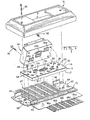
- the kit comprises a plate-like insulating body 11 formed with laterally spaced contact locating means 12a-e and a series of contacts 13a-f ( Figures 4A to 4F) partly formed for assembly with the body by location in preselected of the locating means.
- the body 11 is molded in one piece of suitable plastic material and the contact locating means 12a-e comprise first and second pairs of recesses 14a-e and 15a-e respectively on first and second opposite faces 16 and 17 of the body respectively, the recesses of respective pairs intercommunicating by through sockets 19a-e respectively extending between the faces.
- the three central recesses 14b, c and d on the first face 16 and each of the recesses 15a-e on the second face 17 have flat base walls for reception of contact parts, but the two outer recesses 14a and e communicate at ends remote from the through sockets with bus receiving channels 22 and 24 which extend laterally across the first face 16 and communicate with contact receiving recesses 14d and 14c respectively.
- a third bus receiving channel 25 extends between recess 14d and the approximate mid-point of channel 24.
- Locating posts 26a and 26b upstand from diagonally opposite corners of the second face 17 and a series of sockets 28 for the receipt of self-tapping clamping screws 29 (Figure 1) extend in symmetrically spaced relation across the centerline of the body.
- Locating sockets 30 are formed in the first, upper face 16 adjacent opposite edges of the body on respective opposite sides of the centerline.
- Two further sockets 31 for the receipt of clamping screws 32 extend through the body on opposite sides of the centerline.
- Cavities 20, 20' are formed adjacent opposite edges of the body in the interests of economy of material.
- the kit includes six different stamped and formed contacts 13a-f.
- the contact 13a comprises first contact part or tab 33a and second contact part or tab 34a joined by a neck 35a from respective opposite sides of which extend locating flanges 36a.
- the tabs 33a and 34a each constitute conductor engaging contact parts, a pair of locating recesses 37a being stamped in tab 33a on each side of a screw receiving aperture 38a. Insulation penetrating teeth 39a are pushed out of the tab 34a.
- the tab 33a may be bent to extend transversely of the neck 35a and tab 34a and the flange 36a bent out of the plane of the neck as shown.
- the contact 13a is assembled with the body 11 by insertion from the first face 16 of the body 11, second tab 34a leading into the central through socket 19c so that the first tab 33a is received in a recess 14c on the first face of the body and the neck 35a is received as an interference in the through socket 19c.
- the second tab 34a is then bent to extend transversely of the neck under the first tab so that its inherent resiliency causes it to remain spaced from the body defining an obtuse angle with the neck 35a as shown in Figure 3B. Subsequent engagement with a cable will enable sufficient resilient flexure of the tab towards the body with the teeth 39a remaining proud of the surface 17 to provide a permanent connection to the cable conductor.
- the contact 13d shown in Figure 4D is similar to the contact 13a of Figure 4A except that the aperture 38a is omitted, locating recesses 37d are more closely spaced, and the flanges 36d are bent to extend under the tab 33d. Assembly of contact 13d is similar to that of contact 13a except that tab 34d is bent to extend away from the tab 33d. Contact 13d is intended for location by either contact locating means 12b or 12d ( Figure 2).
- Contacts 13b, c and e ( Figures 4B, C and D) have .tabs 33b, c and e constituting conductor engaging contact parts joined by short necks 41 b, c and e to bus bars 42b, c and e, which are bent, as necessary, to enable receipt in channels 25 and 24 (Figure 5C), channel 24 (Figure 5D), channel 22 ( Figure 5B), or channels 22 and 24 (Figure 5E). It is envisaged that only contacts with straight busses need be supplied, the busses being cut to length and severed in the field.
- tab 33f is bent to extend transversely of neck 41f and trifurcated at a free end to form bus gripping spring fingers 43 returned towards the tab 34f.
- Assembly of the contact with the base 11 and a bus bar is by inserting the contact 13f in locating means 12a (or 12e), tab 34f leading, with bus 42e preloaded in channel 22 so that the fingers 43 grip the bus 42e between them.
- the tab 34f is then bent towards the base 11 to the position shown in Figure 3B.
- the adaptor kit is designed to enable various combinations of connection between cable engaging contacts 63c, d and e of a known single phase duplex outlet 64 connector described in European Patent Application EP-A-90494, and the individual conductors 66a of a triple phase flat cable 67.
- the conductors 66a-e correspond respectively to the secondary, neutral, ground, primary and tertiary lines. When the three phase supply is not connected to the cable, the conductor 66e may be used as an alternative ground.
- an upper metal shield 71 of the cable is turned back and secured by U-form clips 72 to the flanges 46 so that an exposed insulated cable-portion extends across the cable receiving portion of the base plate.
- the base 11 assembled with a chosen combination of contacts is covered with fish paper 18 on surface 16 and surface 17 is clamped against the cable 67 which overlies a layer of fish paper 73 by screws 29 so that the contacts establish connection to the individual conductors as required.
- the duplex outlet 64 is then clamped by screws 32 against the body so that conductors 63c, d and e engage tabs of contacts 12b, c and d.
- the cover is then clamped to the base plate by screws 60.
- an isolated ground secondary phase connection is obtained by locating contact 13d in locating means 12b, respective bus contacts 13c and 13e in 12c and 12d, and spring contacts 13f in 12a and 12e.
- the isolated ground requirement is necessary to prevent a surge (spike) possibility when the usual ground is connected to other equipment and is particularly sought in data applications.
- each tab may be of the same size minimizing die alterations when a series of different contacts are to be stamped and enabling the same press to be used.
Landscapes
- Multi-Conductor Connections (AREA)
- Coupling Device And Connection With Printed Circuit (AREA)
Claims (7)
Applications Claiming Priority (2)
| Application Number | Priority Date | Filing Date | Title |
|---|---|---|---|
| US50159883A | 1983-06-06 | 1983-06-06 | |
| US501598 | 1983-06-06 |
Publications (2)
| Publication Number | Publication Date |
|---|---|
| EP0127962A1 EP0127962A1 (de) | 1984-12-12 |
| EP0127962B1 true EP0127962B1 (de) | 1988-08-24 |
Family
ID=23994223
Family Applications (1)
| Application Number | Title | Priority Date | Filing Date |
|---|---|---|---|
| EP19840303131 Expired EP0127962B1 (de) | 1983-06-06 | 1984-05-09 | Elektrischer Verbinder und Montur |
Country Status (5)
| Country | Link |
|---|---|
| EP (1) | EP0127962B1 (de) |
| JP (1) | JPS607079A (de) |
| CA (1) | CA1235762A (de) |
| DE (1) | DE3473697D1 (de) |
| MX (1) | MX154939A (de) |
Families Citing this family (4)
| Publication number | Priority date | Publication date | Assignee | Title |
|---|---|---|---|---|
| US4563050A (en) * | 1984-07-13 | 1986-01-07 | Thomas & Betts Corporation | Device for flat multiconductor cable connection |
| AU565007B2 (en) * | 1984-07-13 | 1987-09-03 | Thomas & Betts Corporation | Electrical power distribution system |
| US4577920A (en) * | 1984-10-15 | 1986-03-25 | Amp Incorporated | Electrical assembly with cable guiding member |
| US4618203A (en) * | 1985-04-08 | 1986-10-21 | Thomas & Betts Corporation | Isolated ground device for flat undercarpet cable |
Family Cites Families (3)
| Publication number | Priority date | Publication date | Assignee | Title |
|---|---|---|---|---|
| FR1292790A (fr) * | 1960-06-23 | 1962-05-04 | Minnesota Mining & Mfg | Connecteur |
| US3860739A (en) * | 1971-08-03 | 1975-01-14 | Amp Inc | Method and apparatus for a wiring system utilizing wiring devices |
| CH583976A5 (de) * | 1974-08-15 | 1977-01-14 | Aumann Vital L |
-
1984
- 1984-05-09 EP EP19840303131 patent/EP0127962B1/de not_active Expired
- 1984-05-09 DE DE8484303131T patent/DE3473697D1/de not_active Expired
- 1984-05-29 CA CA000455337A patent/CA1235762A/en not_active Expired
- 1984-06-05 MX MX20154984A patent/MX154939A/es unknown
- 1984-06-06 JP JP59116344A patent/JPS607079A/ja active Pending
Also Published As
| Publication number | Publication date |
|---|---|
| MX154939A (es) | 1988-01-08 |
| DE3473697D1 (en) | 1988-09-29 |
| JPS607079A (ja) | 1985-01-14 |
| CA1235762A (en) | 1988-04-26 |
| EP0127962A1 (de) | 1984-12-12 |
Similar Documents
| Publication | Publication Date | Title |
|---|---|---|
| US3617983A (en) | Terminal junction interconnection system | |
| US5203712A (en) | Circuit wiring device | |
| US5123859A (en) | Back-to-back stackable connector for interface bus, and cable clamping system usable therewith | |
| US4040699A (en) | Female connector and escutcheon plate combined therewith for telephone equipment | |
| US4403821A (en) | Wiring line tap | |
| US4317608A (en) | Slotted pate terminal for stranded wire | |
| JP3195345B2 (ja) | 差込み可能接続コネクター及び橋絡アダプター | |
| US4293172A (en) | Case for electrical multiple outlet | |
| US4840578A (en) | Electrical contact | |
| US5697806A (en) | Stackable electrical connector | |
| US4484791A (en) | Connector for multiconductor flat insulated cable | |
| US4973262A (en) | Conduct member for electrical conductors | |
| US4589715A (en) | Electrical connector kit | |
| EP0386742B1 (de) | Elektrischer Verbinder mit Buchsenkontakten verschiedener Grössen und Mittel zur Vermeidung von falschem Anschliessen | |
| EP0017330A1 (de) | Anschlussklemmleiste mit Zwischenwänden für die Zusammenschaltung elektrischer Drähte | |
| US3778750A (en) | Wire termination and splicing system | |
| WO1995031014A1 (en) | Electrical terminal constructed to engage stacked conductors in an insulation displacement manner | |
| US4223971A (en) | Electrical wiring assembly and method | |
| CA1154511A (en) | Electrical connector construction | |
| US7132913B2 (en) | Universal terminal assembly for electric power switch | |
| JPS6130390B2 (de) | ||
| JPS62216185A (ja) | コネクタ | |
| US4564256A (en) | Flat cable transition connector | |
| US5064380A (en) | Electrical tap and splice connector | |
| EP0127962B1 (de) | Elektrischer Verbinder und Montur |
Legal Events
| Date | Code | Title | Description |
|---|---|---|---|
| PUAI | Public reference made under article 153(3) epc to a published international application that has entered the european phase |
Free format text: ORIGINAL CODE: 0009012 |
|
| AK | Designated contracting states |
Designated state(s): BE DE FR GB IT NL |
|
| 17P | Request for examination filed |
Effective date: 19850607 |
|
| 17Q | First examination report despatched |
Effective date: 19860602 |
|
| ITF | It: translation for a ep patent filed | ||
| GRAA | (expected) grant |
Free format text: ORIGINAL CODE: 0009210 |
|
| AK | Designated contracting states |
Kind code of ref document: B1 Designated state(s): BE DE FR GB IT NL |
|
| PG25 | Lapsed in a contracting state [announced via postgrant information from national office to epo] |
Ref country code: BE Effective date: 19880824 |
|
| REF | Corresponds to: |
Ref document number: 3473697 Country of ref document: DE Date of ref document: 19880929 |
|
| ET | Fr: translation filed | ||
| PLBE | No opposition filed within time limit |
Free format text: ORIGINAL CODE: 0009261 |
|
| STAA | Information on the status of an ep patent application or granted ep patent |
Free format text: STATUS: NO OPPOSITION FILED WITHIN TIME LIMIT |
|
| 26N | No opposition filed | ||
| ITTA | It: last paid annual fee | ||
| PGFP | Annual fee paid to national office [announced via postgrant information from national office to epo] |
Ref country code: FR Payment date: 19940407 Year of fee payment: 11 |
|
| PGFP | Annual fee paid to national office [announced via postgrant information from national office to epo] |
Ref country code: GB Payment date: 19940419 Year of fee payment: 11 |
|
| PGFP | Annual fee paid to national office [announced via postgrant information from national office to epo] |
Ref country code: DE Payment date: 19940420 Year of fee payment: 11 |
|
| REG | Reference to a national code |
Ref country code: GB Ref legal event code: 732E |
|
| PG25 | Lapsed in a contracting state [announced via postgrant information from national office to epo] |
Ref country code: GB Effective date: 19950509 |
|
| GBPC | Gb: european patent ceased through non-payment of renewal fee |
Effective date: 19950509 |
|
| PG25 | Lapsed in a contracting state [announced via postgrant information from national office to epo] |
Ref country code: DE Effective date: 19960201 |
|
| PG25 | Lapsed in a contracting state [announced via postgrant information from national office to epo] |
Ref country code: FR Effective date: 19960229 |
|
| REG | Reference to a national code |
Ref country code: FR Ref legal event code: ST |
|
| REG | Reference to a national code |
Ref country code: FR Ref legal event code: ST |
|
| PGFP | Annual fee paid to national office [announced via postgrant information from national office to epo] |
Ref country code: NL Payment date: 19980324 Year of fee payment: 15 |
|
| PG25 | Lapsed in a contracting state [announced via postgrant information from national office to epo] |
Ref country code: NL Free format text: LAPSE BECAUSE OF NON-PAYMENT OF DUE FEES Effective date: 19991201 |
|
| NLV4 | Nl: lapsed or anulled due to non-payment of the annual fee |
Effective date: 19991201 |