EP0128024A2 - Guide d'onde optique monomode conservant les caractéristiques de polarisation - Google Patents
Guide d'onde optique monomode conservant les caractéristiques de polarisation Download PDFInfo
- Publication number
- EP0128024A2 EP0128024A2 EP84303695A EP84303695A EP0128024A2 EP 0128024 A2 EP0128024 A2 EP 0128024A2 EP 84303695 A EP84303695 A EP 84303695A EP 84303695 A EP84303695 A EP 84303695A EP 0128024 A2 EP0128024 A2 EP 0128024A2
- Authority
- EP
- European Patent Office
- Prior art keywords
- core
- fiber
- refractive index
- laminae
- accordance
- Prior art date
- Legal status (The legal status is an assumption and is not a legal conclusion. Google has not performed a legal analysis and makes no representation as to the accuracy of the status listed.)
- Withdrawn
Links
Images


Classifications
-
- G—PHYSICS
- G02—OPTICS
- G02B—OPTICAL ELEMENTS, SYSTEMS OR APPARATUS
- G02B6/00—Light guides; Structural details of arrangements comprising light guides and other optical elements, e.g. couplings
- G02B6/10—Light guides; Structural details of arrangements comprising light guides and other optical elements, e.g. couplings of the optical waveguide type
- G02B6/105—Light guides; Structural details of arrangements comprising light guides and other optical elements, e.g. couplings of the optical waveguide type having optical polarisation effects
-
- C—CHEMISTRY; METALLURGY
- C03—GLASS; MINERAL OR SLAG WOOL
- C03B—MANUFACTURE, SHAPING, OR SUPPLEMENTARY PROCESSES
- C03B37/00—Manufacture or treatment of flakes, fibres, or filaments from softened glass, minerals, or slags
- C03B37/01—Manufacture of glass fibres or filaments
- C03B37/012—Manufacture of preforms for drawing fibres or filaments
- C03B37/01205—Manufacture of preforms for drawing fibres or filaments starting from tubes, rods, fibres or filaments
-
- C—CHEMISTRY; METALLURGY
- C03—GLASS; MINERAL OR SLAG WOOL
- C03B—MANUFACTURE, SHAPING, OR SUPPLEMENTARY PROCESSES
- C03B37/00—Manufacture or treatment of flakes, fibres, or filaments from softened glass, minerals, or slags
- C03B37/01—Manufacture of glass fibres or filaments
- C03B37/012—Manufacture of preforms for drawing fibres or filaments
- C03B37/01205—Manufacture of preforms for drawing fibres or filaments starting from tubes, rods, fibres or filaments
- C03B37/01211—Manufacture of preforms for drawing fibres or filaments starting from tubes, rods, fibres or filaments by inserting one or more rods or tubes into a tube
-
- C—CHEMISTRY; METALLURGY
- C03—GLASS; MINERAL OR SLAG WOOL
- C03B—MANUFACTURE, SHAPING, OR SUPPLEMENTARY PROCESSES
- C03B37/00—Manufacture or treatment of flakes, fibres, or filaments from softened glass, minerals, or slags
- C03B37/01—Manufacture of glass fibres or filaments
- C03B37/012—Manufacture of preforms for drawing fibres or filaments
- C03B37/01205—Manufacture of preforms for drawing fibres or filaments starting from tubes, rods, fibres or filaments
- C03B37/01225—Means for changing or stabilising the shape, e.g. diameter, of tubes or rods in general, e.g. collapsing
- C03B37/0124—Means for reducing the diameter of rods or tubes by drawing, e.g. for preform draw-down
Definitions
- the propagating optical signal retain the polarization characteristics of the input light in the presence of external or internal depolarizing perturbations.
- the change of the polarization state of a propagating signal can be prevented or reduced by employing a fiber that is birefringent, i.e. the core refractive index is different for two orthogonally polarized light waves.
- the polarization performance of a single-mode fiber can be characterized by its beat length L, where L is defined as 2 ⁇ / ⁇ , and ⁇ is the difference in the propagation constants of the two orthogonal polarizations. It is desirable to make fibers with a beat length L of 1 mm or less.
- a single-mode fiber having an azimuthally asymmetric refractive index profile to increase the difference between the propagation constants of the two orthogonal polarizations of the single mode signal is taught in the publication, T. Okoshi et al., "Single-Polarization Single-Mode Optical Fibre with Refractive-Index Pits on Both Sides of Core", Electronics Letters, Vol. 16, No. 18, August 28, 1980, pp 712-713.
- This publication describes a fiber having a circular central region which is divided into a central, rectangularly-shaped core and circular segments of low index along the long sides of the central region. That fiber is reported to have a beat length of 2.3 mm.
- the stabilization of the polarization state in an optical waveguide has also been accomplished by employing an optically anisotropic single crystal as the light conducting medium.
- an optically anisotropic single crystal as the light conducting medium.
- That the birefringent properties of crystals may be explained in terms of the anisotropic electrical properties of the molecules of which the crystals are composed is pointed out in the text: Born et al. Principles of Optics, Pergamon Press, New York (1975) pp 705-708.
- form birefringence may also arise on a scale that is larger than molecular when there is an ordered arrangement of similar particles of optically isotropic material whose size is larger compared with the dimensions of molecules but small compared with the wavelength of light.
- a medium may be visualized as an assembly of thin parallel plates of thickness t l , dielectric constant ⁇ 1 and refractive index n 1 immersed in a medium having a dielectric constant ⁇ 2 and refractive index n 2 .
- the widths of the spaces between the plates is t 2 .
- the aforementioned Dyott et al. patent indiates that an optical waveguide fiber having a crystalline core and glass cladding is subject to such defects as voids lying between the crystal and the glass. Also, since the cylindrical core must be formed as a single crystal, the formation of long lengths of such fiber is very difficult, 200mm lengths of defect-free crystal being mentioned in said Dyott et al. patent.
- the present invention pertains to an optical fiber capable of operating single polarization, single-mode at a wavelength ⁇ .
- the fiber includes a core member surrounded by a cladding member having an average refractive index lower than the average refractive index of the core member.
- the fiber is characterized in that one or both of the core and cladding members comprises a plurality of transparent laminae.
- Each of the laminae has a refractive index different from that of the adjacent laminae, and the thickness of each of the laminae is approximately equal to or less than the wavelength X.
- the present invention relates to an optical fiber in which form birefringence exists due to the fact that either the core or the cladding or both are constructed of substantially parallel, longitudinally extending laminae of transparent material, adjacent ones of which exhibit different refractive index.
- the fiber may contain birefringence caused by one or more of such other factors as stress, refractive index pits adjacent the core, and the like.
- a fiber 14 comprising a core 15 of transparent material surrounded by a transparent cladding 18.
- Core 15 may be formed of a plurality of transparent laminae 17, adjacent ones of which are separated by transparent laminae 16.
- the core comprises the aforementioned laminated structure, and the cladding is either a homogeneous layer, or it consists of a plurality of concentric layers.
- the cladding 18 should also be laminated.
- the cladding comprises transparent laminae 20 separated by transparent laminae 19 of different refractive index than laminae 20. Cladding laminae 19 and 20 are perpendicular to core laminae 16 and 17.
- the birefringent properties of the core member 15 and the cladding member 18 can be characterized in terms of equation (1), and therefore, the thickness of any of the lamina 16, 17, 19 or 20 must be approximately equal to or less than the wavelength a of the light to be propagated through the fiber.
- a fiber would be effective for the purpose of maintaining the polarization of a propagated signal even if the laminae thicknesses were slightly greater than a , although its performance would not be as effective as it would be if the thickness was equal to or less than ⁇ .
- Figure 2 illustrates an embodiment wherein the core 21 is a laminated structure comprising a plurality of alternately disposed laminae 23, 24 that extend parallel to the fiber axis.
- the refractive index of laminae 23 is different from that of laminae 24.
- Cladding 26 is a homogeneous material having a refractive index n c that is lower than the average refractive index of laminae 23 and 24.
- Figure 2 also illustrates the use of stress rods 27, the birefringent effect of which may add to or subtract from the effect produced by the laminated core.
- a birefringent effect is also induced by the stress caused by employing alternate laminae which have different TCE.
- Figure 3 is an enlarged, view of core 21, the diameter of which is 2a.
- the thickness of laminae 23 is shown to be t 1 , the refractive index thereof being n l .
- the thickness of laminae 24 is shown to be t 2 , the refractive index thereof being n 2 .
- the refractive index of the cladding material surrounding the core is n c , as shown in Figure 2.
- Refractive index profiles taken through the core axis in a direction perpendicular to the laminae and along the laminae are illustrated in Figures 4 and 5, respectively.
- the dashed line marked n av which is the average refractive index of the core due to the contributions of laminae 23 and 24, is somewhat higher than the cladding refractive index n .
- Figures 6 and 7 are intended to be illustrative of various profiles which satisfy the requirements of the present invention. Whereas all of the lamina 23 are shown by Figure 4 to have a refractive index n l , these lamina could have different refractive indices as shown in Figure 6, wherein the core refractive index is plotted as a function of radius. Also, as shown in Figure 7, the refractive index within a lamina can be any non-step profile including any ⁇ -type profile or other gradation. Figure 7 also shows that the refractive index within a lamina can increase as a function of distance from the center of the lamina as shown by curve 28, or it can decrease or follow some other function of distance as indicated by curves 29 and 30.
- the circularly-shaped core 21 of Figures 2 and 3 is a convenient shape for coupling light from certain sources to the fiber.
- core shapes such as elliptical or rectangular may be employed in the fiber of the present invention.
- Figures 8 and 9 illustrate two rectangular shapes.
- laminae 31 and 32 form a rectangularly-shaped core having regions 33 of transparent material on opposite sides thereof.
- Regions 33 can be formed of a material having a refractive index n 3 which is lower than the cladding refractive index, in which case they are known as refractive index pits.
- the various portions of the fiber can be formed of any transparent material having the required refractive index, provided that such material can be formed into a fiber.
- transparent material are glass, plastic, crystalline material and combinations thereof.
- low temperature glasses of the type disclosed in U.S. Patents Nos. 4,285,730 and 4,362,819 could be laminated with plastic material.
- one or more of the lamina could be dye-doped and thereby function as an optically active medium suitable for use as a laser or amplifier.
- the thicknesses of the laminae which constitute the core and/or the cladding should be approximately equal to or less than the wavelength of light to be propagated through the fiber during operation thereof as a polarization stabilized or single polarization single-mode fiber.
- the minimum effective thicknesses of the laminae are difusion limited and must therefore be greater than 100 angstroms.
- the following theoretical example illustrates the manner in which fibers designed in accordance with the present invention can achieve submillimeter beat lengths.
- the fiber is to be operated at a wavelength of 632.8 nm.
- the core is constructed in accordance with Figure 8, and the cladding is a homogeneous layer of glass having a refractive index of 1.46.
- the core diameter is 6.0 ⁇ m and w, the smaller dimension of the rectangular core is 3.0 ⁇ m.
- the thicknesses t 1 and t 2 are assumed to be equal, the maximum permissible value thereof being about 0.63 ⁇ m in view of the operating wavelength.
- Laminae 31 have a refractive index of about 1.5.
- Laminae 32 have a refractive index of about 1.45.
- the ratio t 1 /(t 1 +t 2 ) is 0.5, and the average refractive index n av is therefore about 1.475.
- Refractive index pits 33 which have a thickness of 1.5 ⁇ m, exhibit a refractive index of about 1.445.
- the aforementioned refractive index values can be obtained by adding to silica appropriate amounts of one or more dopants such as Ge 0 2 , P 2 O 5 , Al 2 O 3 , B 2 0 3 and F.
- Other optical quality glasses which could provide the necessary refractive indices are also known.
- the operating V-value is assumed to be 3
- the following birefringence characteristics of the fiber can be estimated, assuming that the two types of birefringence that are considered are additive. It is noted that the cutoff V-value would be about 4 in order to obtain single-mode operation.
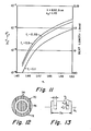
- the beat length L of the fiber operated at 632.8 nm is the ordinate expressed along the right side of the graph.
- the uppermost curve indicates that at f1 equal to 0.5 and n 1 equal to 1.55, the beat length is about 0.8 mm. It is noted that the quantity (n ⁇ 2 -n ⁇ 2 ) is about 2.5 x 10⁻³ for this value of beat length.
- the waveguide effect caused by the generally rectangular core having low index pits on opposite sides there of results in a beat length of about 2.3 mm. If the form birefringence and that due to the refractive index pits are additive, the fiber beat length at 632.8 nm will be about 0.5 mm. It is noted that stress birefringence effects are not considered in this example. The addition of stress rods such as those illustrated in Figure 3 could result in an even lower beat length.
- Fibers of the type illustrated in Figure 1 could be fabricated by forming a preform of slabs of glass having the appropriate refractive index.
- the widths and thicknesses of the glass slabs would be proportional to the widths and thicknesses of the lamina in the resultant fiber.
- the preform so formed could be heated at one end and drawn into a fiber.
- slabs of glass having the appropriate refractive index can be stacked as indicated above and then drawn into an intermediate fiber having an average diameter in the range of about 4 to 10 mm. This drawing operation will cause adjacent slabs to adhere to one another.
- the outer surface of the resultant intermediate fiber can be ground and polished to the desired cross-sectional configuration such as circular. It can then be provided with a layer of cladding glass by inserting it into a tube or by rotating it in a lathe while directing thereon a stream of glass soot as taught in U.S. Patent No. 4,360,371.
- Circular core 70 is formed of laminae 72, adjacent ones of which are separated by laminae 74 of different refractive index.
- One or more regions of depressed refractive index may exist within the core, as taught in said copending application, to reduce dispersion or to provide low dispersion operation over a wide band of wavelengths.
- the depressed refractive index region is in the form of an azimuthally symmetric ring 76.
- the refractive index n of lamina 74 may decrease to a value of n d in region 76.
- the dashed line in Figure 13 is illustrative of the fact that the refractive index nd of region 76 can be lower than the cladding refractive index n .
- the index depression is shown in Figure 13 as being flat, it can be any shape such as rounded or V-shaped. Region 76 could also be azimuthally asymmetric. Furthermore, there may be more than one region of depressed refractive index.
- An index depression may be superimposed on any type of lamina index profile. For example, any of the profiles 28, 29 or 30 of Figure 7 could have superimposed thereon one or more index depressions of the type described above. Whereas the thicknesses of the core laminae must be no greater than approximately the wavelength ⁇ to be propagated through the fiber, the width s of the index depression must be greater than a .
Landscapes
- Chemical & Material Sciences (AREA)
- Engineering & Computer Science (AREA)
- Materials Engineering (AREA)
- Geochemistry & Mineralogy (AREA)
- Manufacturing & Machinery (AREA)
- General Life Sciences & Earth Sciences (AREA)
- Life Sciences & Earth Sciences (AREA)
- Organic Chemistry (AREA)
- Physics & Mathematics (AREA)
- General Physics & Mathematics (AREA)
- Optics & Photonics (AREA)
- Optical Fibers, Optical Fiber Cores, And Optical Fiber Bundles (AREA)
- Optical Integrated Circuits (AREA)
- Manufacture, Treatment Of Glass Fibers (AREA)
- Eyeglasses (AREA)
Applications Claiming Priority (2)
| Application Number | Priority Date | Filing Date | Title |
|---|---|---|---|
| US06/499,898 US4549781A (en) | 1983-06-01 | 1983-06-01 | Polarization-retaining single-mode optical waveguide |
| US499898 | 1983-06-01 |
Publications (2)
| Publication Number | Publication Date |
|---|---|
| EP0128024A2 true EP0128024A2 (fr) | 1984-12-12 |
| EP0128024A3 EP0128024A3 (fr) | 1986-06-25 |
Family
ID=23987205
Family Applications (1)
| Application Number | Title | Priority Date | Filing Date |
|---|---|---|---|
| EP19840303695 Withdrawn EP0128024A3 (fr) | 1983-06-01 | 1984-06-01 | Guide d'onde optique monomode conservant les caractéristiques de polarisation |
Country Status (11)
| Country | Link |
|---|---|
| US (1) | US4549781A (fr) |
| EP (1) | EP0128024A3 (fr) |
| JP (1) | JPS59232301A (fr) |
| KR (1) | KR850000686A (fr) |
| AU (1) | AU2875184A (fr) |
| BR (1) | BR8402407A (fr) |
| DK (1) | DK268384A (fr) |
| ES (1) | ES532804A1 (fr) |
| FI (1) | FI842183L (fr) |
| IL (1) | IL71740A0 (fr) |
| NO (1) | NO842176L (fr) |
Cited By (2)
| Publication number | Priority date | Publication date | Assignee | Title |
|---|---|---|---|---|
| EP0138512B1 (fr) * | 1983-10-03 | 1987-12-02 | Corning Glass Works | Procédé de fabrication d'une fibre laminée à monopolarisation |
| EP0637762A4 (fr) * | 1993-02-25 | 1995-07-05 | Fujikura Ltd | Fibre optique polarisee porteuse d'onde, procede de fabrication, procede de connexion, amplificateur optique, oscillateur laser et coupleur de fibre optique polarisee porteuse d'onde. |
Families Citing this family (22)
| Publication number | Priority date | Publication date | Assignee | Title |
|---|---|---|---|---|
| US4712854A (en) * | 1983-07-11 | 1987-12-15 | Omron Tateisi Electronics Co. | Optical waveguide and method of making the same |
| US4717225A (en) * | 1984-10-11 | 1988-01-05 | Litton Systems, Inc. | Form polarizing fibers and method of fabrication |
| US4711525A (en) * | 1985-05-08 | 1987-12-08 | Litton Systems, Inc. | Polarizing optical fiber with absorbing jacket |
| US4997282A (en) * | 1986-09-19 | 1991-03-05 | Litton Systems, Inc. | Dual fiber optic gyroscope |
| US4842358A (en) * | 1987-02-20 | 1989-06-27 | Litton Systems, Inc. | Apparatus and method for optical signal source stabilization |
| US4915503A (en) * | 1987-09-01 | 1990-04-10 | Litton Systems, Inc. | Fiber optic gyroscope with improved bias stability and repeatability and method |
| EP0308602A3 (fr) * | 1987-09-25 | 1990-01-10 | Siemens Aktiengesellschaft | Guide d'ondes optiques enterré biréfringent ou structure de tels guides d'ondes et méthode pour la fabrication d'un tel guide d'ondes ou d'une telle structure |
| WO1989011109A1 (fr) * | 1988-05-03 | 1989-11-16 | The University Of Sydney | Fibre optique circulairement bi-refringente |
| US4896942A (en) * | 1989-02-03 | 1990-01-30 | Minnesota Mining And Manufacturing Company | Polarization-maintaining optical fiber |
| EP0413387A1 (fr) * | 1989-08-16 | 1991-02-20 | Koninklijke Philips Electronics N.V. | Fibre optique en mode simple maintenant la polarisation |
| IT1238535B (it) * | 1989-11-14 | 1993-08-18 | Cselt Centro Studi Lab Telecom | Sistema di comunicazione coerente in fibra ottica a diversita' di polarizzazione in trasmissione |
| US5602947A (en) * | 1995-01-05 | 1997-02-11 | Ceram Optee Industries, Inc. | Anti-reflective mid-infrared optical fiber and micro optical components |
| US6151336A (en) * | 1998-02-11 | 2000-11-21 | Sorrento Networks, Inc. | Time division multiplexing expansion subsystem |
| US6400478B1 (en) | 1998-04-02 | 2002-06-04 | Sorrento Networks, Inc. | Wavelength-division-multiplexed optical transmission system with expanded bidirectional transmission capacity over a single fiber |
| US6298103B1 (en) | 1998-06-16 | 2001-10-02 | Sorrento Networks Corporation | Flexible clock and data recovery module for a DWDM optical communication system with multiple clock rates |
| TW536640B (en) * | 2001-04-13 | 2003-06-11 | Furukawa Electric Co Ltd | Coated optical fiber |
| CA2386975A1 (fr) * | 2001-05-16 | 2002-11-16 | Thomas Szkopek | Fibre multimode nouvelle pour reseaux de bragg a bande etroite |
| FI20045308L (fi) * | 2004-08-26 | 2006-02-27 | Corelase Oy | Optinen kuituvahvistin, jossa on vahvistuksen muotoerottelu |
| NL2007447C2 (nl) * | 2011-09-20 | 2013-03-21 | Draka Comteq Bv | Werkwijze voor de vervaardiging van een primaire voorvorm voor optische vezels, primaire voorvorm, uiteindelijke voorvorm, optische vezel. |
| NL2007448C2 (nl) * | 2011-09-20 | 2013-03-21 | Draka Comteq Bv | Werkwijze voor de vervaardiging van een primaire voorvorm voor optische vezels, primaire voorvorm, uiteindelijke voorvorm, optische vezels. |
| CN110780377A (zh) * | 2019-09-25 | 2020-02-11 | 无锡法尔胜光电科技有限公司 | 一种保偏光纤及其制备方法 |
| US20240230984A9 (en) * | 2022-10-19 | 2024-07-11 | Lumentum Operations Llc | Controlling refractive index profile during fiber preform manufacturing |
Family Cites Families (12)
| Publication number | Priority date | Publication date | Assignee | Title |
|---|---|---|---|---|
| GB1514477A (en) * | 1974-09-24 | 1978-06-14 | Post Office | Optical devices |
| US4274854A (en) * | 1978-01-13 | 1981-06-23 | Bell Telephone Laboratories, Incorporated | Polarization-preserving optical fiber |
| US4179189A (en) * | 1978-01-13 | 1979-12-18 | Bell Telephone Laboratories, Incorporated | Single polarization optical fibers and methods of fabrication |
| US4265515A (en) * | 1978-05-08 | 1981-05-05 | International Telephone And Telegraph Corporation | Optical fiber waveguide with effective refractive index profile |
| US4184859A (en) * | 1978-06-09 | 1980-01-22 | International Telephone And Telegraph Corporation | Method of fabricating an elliptical core single mode fiber |
| DE3064691D1 (en) * | 1979-06-19 | 1983-10-06 | Andrew Corp | Dielectric waveguides and method of propagating polarized electromagnetic waves and communication apparatus and system using such waveguides and method |
| US4285730A (en) * | 1979-10-05 | 1981-08-25 | Corning Glass Works | Moldable glasses |
| US4362819A (en) * | 1980-02-26 | 1982-12-07 | Corning Glass Works | Moldable fluoroaluminophosphate glasses |
| US4354736A (en) * | 1980-06-18 | 1982-10-19 | International Telephone And Telegraph Corporation | Stress-induced birefringent single mode optical fiber and a method of fabricating the same |
| US4372646A (en) * | 1980-07-31 | 1983-02-08 | Rockwell International Corporation | Birefringent electromagnetic transmission line that preserves the state of polarized radiation propagating therein |
| DE3047290A1 (de) * | 1980-12-16 | 1982-07-29 | Licentia Patent-Verwaltungs-Gmbh, 6000 Frankfurt | "wellenleiter und ein verfahren zu dessen herstellung" |
| US4360371A (en) * | 1981-03-30 | 1982-11-23 | Corning Glass Works | Method of making polarization retaining single-mode optical waveguide |
-
1983
- 1983-06-01 US US06/499,898 patent/US4549781A/en not_active Expired - Fee Related
-
1984
- 1984-05-03 IL IL71740A patent/IL71740A0/xx unknown
- 1984-05-18 BR BR8402407A patent/BR8402407A/pt unknown
- 1984-05-25 ES ES532804A patent/ES532804A1/es not_active Expired
- 1984-05-28 AU AU28751/84A patent/AU2875184A/en not_active Abandoned
- 1984-05-29 JP JP59107682A patent/JPS59232301A/ja active Pending
- 1984-05-30 NO NO842176A patent/NO842176L/no unknown
- 1984-05-30 DK DK268384A patent/DK268384A/da not_active Application Discontinuation
- 1984-05-31 FI FI842183A patent/FI842183L/fi not_active Application Discontinuation
- 1984-05-31 KR KR1019840003031A patent/KR850000686A/ko not_active Withdrawn
- 1984-06-01 EP EP19840303695 patent/EP0128024A3/fr not_active Withdrawn
Cited By (3)
| Publication number | Priority date | Publication date | Assignee | Title |
|---|---|---|---|---|
| EP0138512B1 (fr) * | 1983-10-03 | 1987-12-02 | Corning Glass Works | Procédé de fabrication d'une fibre laminée à monopolarisation |
| EP0637762A4 (fr) * | 1993-02-25 | 1995-07-05 | Fujikura Ltd | Fibre optique polarisee porteuse d'onde, procede de fabrication, procede de connexion, amplificateur optique, oscillateur laser et coupleur de fibre optique polarisee porteuse d'onde. |
| US5689578A (en) * | 1993-02-25 | 1997-11-18 | Fujikura Ltd. | Polarized wave holding optical fiber, production method therefor, connection method therefor, optical amplifier, laser oscillator and polarized wave holding optical fiber coupler |
Also Published As
| Publication number | Publication date |
|---|---|
| FI842183A0 (fi) | 1984-05-31 |
| NO842176L (no) | 1984-12-03 |
| DK268384D0 (da) | 1984-05-30 |
| BR8402407A (pt) | 1985-04-02 |
| ES532804A1 (es) | 1986-04-01 |
| AU2875184A (en) | 1984-12-06 |
| IL71740A0 (en) | 1984-09-30 |
| US4549781A (en) | 1985-10-29 |
| JPS59232301A (ja) | 1984-12-27 |
| FI842183A7 (fi) | 1984-12-02 |
| DK268384A (da) | 1984-12-02 |
| FI842183L (fi) | 1984-12-02 |
| KR850000686A (ko) | 1985-02-28 |
| EP0128024A3 (fr) | 1986-06-25 |
Similar Documents
| Publication | Publication Date | Title |
|---|---|---|
| US4549781A (en) | Polarization-retaining single-mode optical waveguide | |
| EP0109604B1 (fr) | Fibre optique avec maintien du plan de polarisation | |
| KR910000718B1 (ko) | 광 파이버 | |
| KR0172600B1 (ko) | 단일모드, 단일편광 광섬유 | |
| US4778234A (en) | Integrated optics polarizing device | |
| CA1202506A (fr) | Fibre monomode a faible deperdition | |
| US4179189A (en) | Single polarization optical fibers and methods of fabrication | |
| Takato et al. | Low-loss high-silica single-mode channel waveguides | |
| Cohen et al. | Effect of temperature on transmission in lightguides | |
| EP0145031B1 (fr) | Procédé de fabrication d'une préforme pour guide d'onde optique | |
| JP3734733B2 (ja) | 偏波保持光ファイバおよび絶対単一偏波光ファイバ | |
| EP0319319B1 (fr) | Fibre optique à polarisation unique | |
| US6853786B2 (en) | Photonic-crystal fibers and photonic-crystal fiber devices | |
| CA1248386A (fr) | Fibres guides d'ondes optiques a quadruple enrobage | |
| CN114114526B (zh) | 空芯负曲率光纤偏振分束器 | |
| US4717225A (en) | Form polarizing fibers and method of fabrication | |
| EP1420276A1 (fr) | Fibre optique à cristaux photoniques préservant la polarisation de la lumière | |
| US4711525A (en) | Polarizing optical fiber with absorbing jacket | |
| Katsuyama et al. | Low-loss single polarization fibers | |
| Maegami et al. | CMOS-Compatible Silicon Nitride Waveguide on Silicon Photonics Platform | |
| EP1275990A2 (fr) | Fibre optique à maintien de polarisation | |
| KR100443680B1 (ko) | 포토닉 밴드갭을 이용한 광섬유 및 그 제조방법 | |
| Baghdadi | Designs for zero polarization-mode dispersion and polarization-maintaining fibers | |
| JPS62276510A (ja) | 応力付与形偏波保持光フアイバ | |
| CN111694091A (zh) | 一种气体包层低损耗偏振光纤 |
Legal Events
| Date | Code | Title | Description |
|---|---|---|---|
| PUAI | Public reference made under article 153(3) epc to a published international application that has entered the european phase |
Free format text: ORIGINAL CODE: 0009012 |
|
| AK | Designated contracting states |
Designated state(s): AT BE CH DE FR GB IT LI NL SE |
|
| PUAL | Search report despatched |
Free format text: ORIGINAL CODE: 0009013 |
|
| AK | Designated contracting states |
Kind code of ref document: A3 Designated state(s): AT BE CH DE FR GB IT LI NL SE |
|
| STAA | Information on the status of an ep patent application or granted ep patent |
Free format text: STATUS: THE APPLICATION HAS BEEN WITHDRAWN |
|
| 18W | Application withdrawn |
Withdrawal date: 19860919 |
|
| RIN1 | Information on inventor provided before grant (corrected) |
Inventor name: NOLAN, DANIEL ALOYSIUS Inventor name: BHAGAVATULA, VENKATA ADISESHAIAH |