EP0128095A2 - Belüftungssystem für eine Wohnung - Google Patents
Belüftungssystem für eine Wohnung Download PDFInfo
- Publication number
- EP0128095A2 EP0128095A2 EP84401123A EP84401123A EP0128095A2 EP 0128095 A2 EP0128095 A2 EP 0128095A2 EP 84401123 A EP84401123 A EP 84401123A EP 84401123 A EP84401123 A EP 84401123A EP 0128095 A2 EP0128095 A2 EP 0128095A2
- Authority
- EP
- European Patent Office
- Prior art keywords
- extraction
- mechanical
- ventilation system
- air
- passage
- Prior art date
- Legal status (The legal status is an assumption and is not a legal conclusion. Google has not performed a legal analysis and makes no representation as to the accuracy of the status listed.)
- Granted
Links
Images

Classifications
-
- F—MECHANICAL ENGINEERING; LIGHTING; HEATING; WEAPONS; BLASTING
- F24—HEATING; RANGES; VENTILATING
- F24F—AIR-CONDITIONING; AIR-HUMIDIFICATION; VENTILATION; USE OF AIR CURRENTS FOR SCREENING
- F24F7/00—Ventilation
- F24F7/04—Ventilation with ducting systems, e.g. by double walls; with natural circulation
- F24F7/06—Ventilation with ducting systems, e.g. by double walls; with natural circulation with forced air circulation, e.g. by fan positioning of a ventilator in or against a conduit
-
- F—MECHANICAL ENGINEERING; LIGHTING; HEATING; WEAPONS; BLASTING
- F24—HEATING; RANGES; VENTILATING
- F24F—AIR-CONDITIONING; AIR-HUMIDIFICATION; VENTILATION; USE OF AIR CURRENTS FOR SCREENING
- F24F7/00—Ventilation
- F24F7/007—Ventilation with forced flow
Definitions
- the present invention relates to a ventilation system for a residential accommodation comprising at least one service room with an air outlet communicating with an extraction duct and provided with mechanical air extraction means.
- Ventilation is provided either by forced mechanical extractors, or naturally using vertical ducts.
- Natural ventilation requires vertical exhaust ducts and air outlets of sufficient section to ensure the maximum desired flow. This results in significant energy losses during the cold season.
- the mechanical extractors allow the use of conduits with horizontal parts and counter-slopes and with a reduced section, and facilitate the regulation of the flow rate, but must operate continuously. These are generally electrically operated fans. Their permanent operation entails a certain consumption of energy and is dependent on the supply of electricity. In the event of a power outage or failure, the minimum flow required cannot be guaranteed.
- the present invention aims to remedy the aforementioned drawbacks of known ventilation systems.
- the extraction duct is an individual duct without horizontal or counter part, dimensioned to provide a minimum extraction flow required by natural ventilation, said minimum flow being obtained at least in part by the passage of air through the mechanical extraction means when they are stopped and a desired higher extraction rate being obtained through the mechanical extraction means by switching on the latter.
- the mechanical extraction means must only be actuated to ensure a desired higher extraction rate, which limits the energy consumption. Furthermore, even in the event of a breakdown or cut in the power supply to the mechanical extraction means, the minimum extraction flow rate is guaranteed.
- the mechanical extraction means allowing the passage of air at rest are for example constituted by a helical mechanical extractor (fan with blades).
- the air outlet comprises, in particular when the service room is a kitchen, an additional mouth placed in bypass of the mechanical extraction means and intended, when it is open , to ensure the minimum flow required in combination with the passage through the mechanical extraction means.
- the starting of the mechanical extraction means can then be controlled by closing the additional mouth.
- the minimum flow is defined by the total cross-section of the air passage when the mechanical extraction means are at rest while the maximum flow is ensured only through the mechanical extraction means in operation; the desired minimum and maximum flow values can therefore be predetermined with precision.
- the ventilation system according to the invention can be used for accommodation in individual or collective dwellings. Air inlets are placed in main rooms and mixed exhaust air outlets (natural and mechanical) are placed in service rooms.
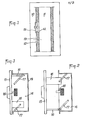
- FIG. 1 illustrates an air outlet making a room 10 communicate with an individual extraction duct 11, for example made of concrete.
- This outlet includes a mouth 12 in which is mounted an electric helical extractor 13.
- an electric helical extractor 13 When the latter is stopped, a minimum extraction flow is obtained with passage of air between the blades of the propeller of the extractor , the conduit 11 being vertical, that is to say without horizontal or oontrepente part. Switching on the extractor provides the desired maximum flow rate.
- an additional mouth 14 can be provided next to the mouth 12, bypass on the extractor 13, to directly communicate the part 10 with the conduit 11.
- the mouth 14 is provided with a cover 15 having tabs 16 guided on an inclined circular ramp 17 so that the mouth 12 can be opened ( Figure 2) or closed ( Figures 1 and 3) by rotating the cover 180 degrees.
- a microswitch 18 is disposed in the mouth 14 and is closed when the cover 15 is in the closed position, to control the actuation of the extractor 13; the maximum extraction rate is thus ensured only through the mouth 12.
- the starting of the extractor can be carried out by other means, for example a manual switch.
- the adjustment of the passage section through the mouth 14 to ensure the minimum flow required in combination with the passage through the blades of the extractor 13 is carried out according to the characteristics of the housing during the installation of the ventilation system.
- a mouth 14 is used for this purpose, the rear wall 19 of which is divided into several calibrated knockout sectors 19a (FIG. 4); the adjustment of the air passage section is achieved by knocking down one or more of these sectors.
- the maximum flow rate can be adjusted according to the characteristics of the housing either by adapting the extractor 13 or by increasing the pressure drop by means of a more or less closed grid placed in the mouth 14, the extractor 13 then being of a standard type.
- FIG. 5 illustrates another embodiment of an air outlet in a ventilation system according to the invention, this air outlet being suitable in particular for service rooms other than kitchens (for example bathrooms and WC).
- the extraction is carried out successively through a self-adjusting bellows mouth 22, of a type well known per se, and an electric helical extractor 23 placed one behind the other between the part 20 and the vertical duct. individual extraction 21.
- the minimum required extraction flow is provided by natural ventilation with air passing through the mouth 22 and between the blades of the extractor propeller 23.
- the maximum desired extraction flow is ensured by switching on the extractor. This start-up can be controlled either by a specific switch or using of the light circuit in room 20. Regulation of maximum flow is ensured by the self-adjusting mouth 22.
- the air inlets of the ventilation system according to the invention may consist, as known per se, of self-adjusting orifices provided to ensure the maximum desired flow.
- the individual extraction conduits can be placed in a battery and their lower part can be used as a sheath for the passage of the power supply conductors of the extractors.
Landscapes
- Engineering & Computer Science (AREA)
- Chemical & Material Sciences (AREA)
- Combustion & Propulsion (AREA)
- Mechanical Engineering (AREA)
- General Engineering & Computer Science (AREA)
- Ventilation (AREA)
- Building Environments (AREA)
- Air-Flow Control Members (AREA)
- Input Circuits Of Receivers And Coupling Of Receivers And Audio Equipment (AREA)
- Casings For Electric Apparatus (AREA)
- Cooling Or The Like Of Electrical Apparatus (AREA)
Priority Applications (1)
| Application Number | Priority Date | Filing Date | Title |
|---|---|---|---|
| AT84401123T ATE29777T1 (de) | 1983-06-03 | 1984-06-01 | Belueftungssystem fuer eine wohnung. |
Applications Claiming Priority (2)
| Application Number | Priority Date | Filing Date | Title |
|---|---|---|---|
| FR8309263 | 1983-06-03 | ||
| FR8309263A FR2550323B1 (fr) | 1983-06-03 | 1983-06-03 | Systeme de ventilation pour un logement |
Publications (3)
| Publication Number | Publication Date |
|---|---|
| EP0128095A2 true EP0128095A2 (de) | 1984-12-12 |
| EP0128095A3 EP0128095A3 (en) | 1985-01-09 |
| EP0128095B1 EP0128095B1 (de) | 1987-09-16 |
Family
ID=9289469
Family Applications (1)
| Application Number | Title | Priority Date | Filing Date |
|---|---|---|---|
| EP84401123A Expired EP0128095B1 (de) | 1983-06-03 | 1984-06-01 | Belüftungssystem für eine Wohnung |
Country Status (5)
| Country | Link |
|---|---|
| EP (1) | EP0128095B1 (de) |
| AT (1) | ATE29777T1 (de) |
| DE (1) | DE3466275D1 (de) |
| ES (1) | ES8503112A1 (de) |
| FR (1) | FR2550323B1 (de) |
Cited By (1)
| Publication number | Priority date | Publication date | Assignee | Title |
|---|---|---|---|---|
| FR2616521A1 (fr) * | 1987-06-12 | 1988-12-16 | Halton Oy | Procede et appareillage de regulation du flux d'air minimal qu'il faut introduire dans une piece a ventiler ou extraire de celle-ci |
Family Cites Families (6)
| Publication number | Priority date | Publication date | Assignee | Title |
|---|---|---|---|---|
| DE367051C (de) * | 1923-01-16 | Gottfried Ribbe | Elektrischer Deckenluefter in Verbindung mit einer Beleuchtungseinrichtung | |
| FR1080990A (fr) * | 1953-07-07 | 1954-12-15 | Aérotherme-relais | |
| DE1107916B (de) * | 1960-05-16 | 1961-05-31 | Linke Fa Paul | Fensterluefter |
| DE977753C (de) * | 1964-01-15 | 1969-09-18 | Keller & Knappich Ges Mit Besc | Belueftung von Panzer-Tuermen und -Fahrzeugen |
| DE1922943A1 (de) * | 1969-05-06 | 1970-12-10 | Wakofic Bautechnik Gmbh & Co K | Lueftungsschachtanlage |
| DE1959234A1 (de) * | 1969-11-26 | 1971-06-09 | Becker Kg E & A | Anordnung zur Be- und Entlueftung von Raeumen |
-
1983
- 1983-06-03 FR FR8309263A patent/FR2550323B1/fr not_active Expired
-
1984
- 1984-06-01 AT AT84401123T patent/ATE29777T1/de active
- 1984-06-01 DE DE8484401123T patent/DE3466275D1/de not_active Expired
- 1984-06-01 EP EP84401123A patent/EP0128095B1/de not_active Expired
- 1984-06-01 ES ES533061A patent/ES8503112A1/es not_active Expired
Cited By (1)
| Publication number | Priority date | Publication date | Assignee | Title |
|---|---|---|---|---|
| FR2616521A1 (fr) * | 1987-06-12 | 1988-12-16 | Halton Oy | Procede et appareillage de regulation du flux d'air minimal qu'il faut introduire dans une piece a ventiler ou extraire de celle-ci |
Also Published As
| Publication number | Publication date |
|---|---|
| ES533061A0 (es) | 1985-02-01 |
| ES8503112A1 (es) | 1985-02-01 |
| EP0128095A3 (en) | 1985-01-09 |
| FR2550323A1 (fr) | 1985-02-08 |
| EP0128095B1 (de) | 1987-09-16 |
| ATE29777T1 (de) | 1987-10-15 |
| DE3466275D1 (en) | 1987-10-22 |
| FR2550323B1 (fr) | 1988-09-23 |
Similar Documents
| Publication | Publication Date | Title |
|---|---|---|
| CH663658A5 (fr) | Dispositif de ventilation. | |
| EP0128095B1 (de) | Belüftungssystem für eine Wohnung | |
| EP0606247A1 (de) | Elektrischer speicherheizkörper mit modularen elementen. | |
| EP1899652B1 (de) | Lüftungseinrichtung für eine küche | |
| FR2828557A1 (fr) | Groupe de ventilation mecanique commande par pressostat | |
| EP1277017B1 (de) | Vorrichtung zur thermischen luftbehandlung und zur belüftung in einem gebäude mit mehreren räumen | |
| EP1598514B1 (de) | Luftabsaugevorrichtung | |
| FR2835598A1 (fr) | Installation de ventilation mecanique controlee equipee d'un dispositif de pilotage | |
| EP1553357A1 (de) | Vorrichtung zur Belüftungsregelung von dem Raum eines Gebäudes | |
| EP3343121B1 (de) | Luftabsaug- oder -einblasöffnung | |
| EP1541925A1 (de) | Bauraumsparendes gasführendes Leitungssystem für eine Wohnungseinheit | |
| EP0088736A2 (de) | Vorfabrizierte zentrale elektrisch aktivierte Installation für Brauchwasser | |
| EP2302301B1 (de) | Verbesserte Anlage für Gaszirkulation für ein Wohngebäude | |
| FR2571477A1 (fr) | Installation de ventilation mecanique modulante | |
| EP4191157A1 (de) | System zur steuerung einer feuchtigkeitseinstellbaren luftextraktionsvorrichtung für eine belüftungsanlage und belüftungsanlage mit solch einem steuerungssystem | |
| EP3001117A1 (de) | Anlageneinheit für einen raum, lüftungs- und klimaanlage, die eine solche einheit umfasst, und lüftungs- und klimaanlage in einem gebäude | |
| FR3144263A1 (fr) | Dispositif et procédé de gestion de l’air d’une habitation, à modes diurnes et nocturnes | |
| FR2685455A1 (fr) | Perfectionnements apportes aux appareils pour la ventilation mecanique des locaux. | |
| EP0193482A1 (de) | Steuerungszentrale, insbesondere für einen Zwei-Energiekessel oder für jede andere Art zum Betreiben einer Zentralheizung mit speicherfähigem Brennstoff mit mehreren Betriebsarten | |
| EP1228333A1 (de) | Modularer gasbeheizter kombikessel | |
| JPS6212183Y2 (de) | ||
| BE1022750B1 (fr) | Installation de ventilation d'un ensemble de logements munis d'un chauffe-eau thermodynamique | |
| FR2481759A1 (fr) | Turbo-accelerateur a commande automatique | |
| FR2505940A1 (fr) | Procede et dispositif de commande automatique de la vitesse d'un ventilateur dans une installation de ventilation | |
| EP4210080A1 (de) | Kaminplatte zum zerkleinern und löschen von bogen und kamin mit einer solchen platte |
Legal Events
| Date | Code | Title | Description |
|---|---|---|---|
| PUAI | Public reference made under article 153(3) epc to a published international application that has entered the european phase |
Free format text: ORIGINAL CODE: 0009012 |
|
| PUAL | Search report despatched |
Free format text: ORIGINAL CODE: 0009013 |
|
| AK | Designated contracting states |
Designated state(s): AT BE CH DE GB IT LI LU NL SE |
|
| AK | Designated contracting states |
Designated state(s): AT BE CH DE GB IT LI LU NL SE |
|
| 17P | Request for examination filed |
Effective date: 19850608 |
|
| GRAA | (expected) grant |
Free format text: ORIGINAL CODE: 0009210 |
|
| AK | Designated contracting states |
Kind code of ref document: B1 Designated state(s): AT BE CH DE GB IT LI LU NL SE |
|
| REF | Corresponds to: |
Ref document number: 29777 Country of ref document: AT Date of ref document: 19871015 Kind code of ref document: T |
|
| ITF | It: translation for a ep patent filed | ||
| REF | Corresponds to: |
Ref document number: 3466275 Country of ref document: DE Date of ref document: 19871022 |
|
| GBV | Gb: ep patent (uk) treated as always having been void in accordance with gb section 77(7)/1977 [no translation filed] | ||
| PLBE | No opposition filed within time limit |
Free format text: ORIGINAL CODE: 0009261 |
|
| STAA | Information on the status of an ep patent application or granted ep patent |
Free format text: STATUS: NO OPPOSITION FILED WITHIN TIME LIMIT |
|
| 26N | No opposition filed | ||
| GBRI | Gb: ep (uk) patent reinstated (gb rule 110(3)a/1987) | ||
| GBT | Gb: translation of ep patent filed (gb section 77(6)(a)/1977) | ||
| PGFP | Annual fee paid to national office [announced via postgrant information from national office to epo] |
Ref country code: AT Payment date: 19920525 Year of fee payment: 9 |
|
| PGFP | Annual fee paid to national office [announced via postgrant information from national office to epo] |
Ref country code: GB Payment date: 19920526 Year of fee payment: 9 |
|
| PGFP | Annual fee paid to national office [announced via postgrant information from national office to epo] |
Ref country code: CH Payment date: 19920612 Year of fee payment: 9 |
|
| PGFP | Annual fee paid to national office [announced via postgrant information from national office to epo] |
Ref country code: DE Payment date: 19920622 Year of fee payment: 9 |
|
| PGFP | Annual fee paid to national office [announced via postgrant information from national office to epo] |
Ref country code: SE Payment date: 19920626 Year of fee payment: 9 |
|
| PGFP | Annual fee paid to national office [announced via postgrant information from national office to epo] |
Ref country code: BE Payment date: 19920629 Year of fee payment: 9 |
|
| ITTA | It: last paid annual fee | ||
| PGFP | Annual fee paid to national office [announced via postgrant information from national office to epo] |
Ref country code: NL Payment date: 19920630 Year of fee payment: 9 |
|
| PGFP | Annual fee paid to national office [announced via postgrant information from national office to epo] |
Ref country code: LU Payment date: 19920701 Year of fee payment: 9 |
|
| EPTA | Lu: last paid annual fee | ||
| PG25 | Lapsed in a contracting state [announced via postgrant information from national office to epo] |
Ref country code: LU Free format text: LAPSE BECAUSE OF NON-PAYMENT OF DUE FEES Effective date: 19930601 Ref country code: GB Effective date: 19930601 Ref country code: AT Effective date: 19930601 |
|
| PG25 | Lapsed in a contracting state [announced via postgrant information from national office to epo] |
Ref country code: SE Effective date: 19930602 |
|
| PG25 | Lapsed in a contracting state [announced via postgrant information from national office to epo] |
Ref country code: LI Effective date: 19930630 Ref country code: CH Effective date: 19930630 Ref country code: BE Effective date: 19930630 |
|
| BERE | Be: lapsed |
Owner name: CENTRE D'ETUDES ET DE RECHERCHES DE L'INDUSTRIE D Effective date: 19930630 |
|
| PG25 | Lapsed in a contracting state [announced via postgrant information from national office to epo] |
Ref country code: NL Effective date: 19940101 |
|
| GBPC | Gb: european patent ceased through non-payment of renewal fee |
Effective date: 19930601 |
|
| NLV4 | Nl: lapsed or anulled due to non-payment of the annual fee | ||
| REG | Reference to a national code |
Ref country code: CH Ref legal event code: PL |
|
| PG25 | Lapsed in a contracting state [announced via postgrant information from national office to epo] |
Ref country code: DE Effective date: 19940301 |
|
| EUG | Se: european patent has lapsed |
Ref document number: 84401123.9 Effective date: 19940110 |