EP0128100B1 - Maschine zum Anbringen und Befestigen von Verbindungsteilen an Reissverschlussträgerbändern - Google Patents
Maschine zum Anbringen und Befestigen von Verbindungsteilen an Reissverschlussträgerbändern Download PDFInfo
- Publication number
- EP0128100B1 EP0128100B1 EP84401140A EP84401140A EP0128100B1 EP 0128100 B1 EP0128100 B1 EP 0128100B1 EP 84401140 A EP84401140 A EP 84401140A EP 84401140 A EP84401140 A EP 84401140A EP 0128100 B1 EP0128100 B1 EP 0128100B1
- Authority
- EP
- European Patent Office
- Prior art keywords
- ribbon
- strip
- pincers
- machine
- guiding
- Prior art date
- Legal status (The legal status is an assumption and is not a legal conclusion. Google has not performed a legal analysis and makes no representation as to the accuracy of the status listed.)
- Expired
Links
Images
Classifications
-
- D—TEXTILES; PAPER
- D05—SEWING; EMBROIDERING; TUFTING
- D05B—SEWING
- D05B3/00—Sewing apparatus or machines with mechanism for lateral movement of the needle or the work or both for making ornamental pattern seams, for sewing buttonholes, for reinforcing openings or for fastening articles, e.g. buttons, by sewing
- D05B3/12—Sewing apparatus or machines with mechanism for lateral movement of the needle or the work or both for making ornamental pattern seams, for sewing buttonholes, for reinforcing openings or for fastening articles, e.g. buttons, by sewing for fastening articles by sewing
- D05B3/20—Sewing apparatus or machines with mechanism for lateral movement of the needle or the work or both for making ornamental pattern seams, for sewing buttonholes, for reinforcing openings or for fastening articles, e.g. buttons, by sewing for fastening articles by sewing labels
-
- A—HUMAN NECESSITIES
- A44—HABERDASHERY; JEWELLERY
- A44B—BUTTONS, PINS, BUCKLES, SLIDE FASTENERS, OR THE LIKE
- A44B19/00—Slide fasteners
- A44B19/42—Making by processes not fully provided for in one other class, e.g. B21D53/50, B21F45/18, B22D17/16, B29D5/00
-
- A—HUMAN NECESSITIES
- A44—HABERDASHERY; JEWELLERY
- A44B—BUTTONS, PINS, BUCKLES, SLIDE FASTENERS, OR THE LIKE
- A44B19/00—Slide fasteners
- A44B19/42—Making by processes not fully provided for in one other class, e.g. B21D53/50, B21F45/18, B22D17/16, B29D5/00
- A44B19/60—Applying end stops upon stringer tapes
Definitions
- the subject of the invention is a machine, the role of which is to automatically pose and fix a junction tab used to join transversely the two parallel strips which constitute the slider closures.
- Slider closures are used a lot in making clothes; we know that this kind of closure is presented as a ribbon composed of two parallel strips which have on two longitudinal edges close to each other stapling means that a slider allows to hang together or release.
- closures are supplied by manufacturers in long rolls; intervals where the strips are devoid of attachment means separate the successive closings.
- a transverse joining tab which securely joins the two parallel strips, below the hooking means when the closure is put in position of use.
- This connecting tab makes the closure easier to handle, to set up and to sew on clothes. It also contributes to reinforcing the stop of the cursor travel which is provided on the stapling means.
- Document GB-A-2 044 140 describes a machine in which means for advancing the two parts of a continuous strip of spaced-apart slide fasteners are combined with means for cutting these sections into sections, then these are introduced into a pairing unit where the complementary elements are engaged in one another.
- the main object of the invention is to achieve a machine of a similar kind which sets up and sews connecting tabs on slider closures supplied in strips of very long length rolled up.
- this machine further comprises a sewing machine having a lifting presser foot, the means for guiding the band guiding it under the presser foot and the ribbon cutting member being placed above this band just upstream of this same sewing machine, a clamp with two branches arranged transversely to the ribbon mounted movable on the one hand in a transverse direction with respect to this ribbon between a first position in which the two branches contain the ribbon upstream of the cutting member and a second posit ion in which the two branches are set back relative to the ribbon, on the other hand in a longitudinal direction relative to the ribbon between a first position upstream of the cutting member and a second position downstream of the presser foot of the machine sew at the upper face
- This element comprises an actuator with an alternative stroke in a direction transverse to the ribbon so that the arms of the clamp can be moved between a first position in which they contain the ribbon and a second position in which they are recessed with respect to the same ribbon.
- the element disposed in a direction transverse to the strip of slide fasteners is coupled to the piston rod of a jack by means of a slide provided with a rack; this element is provided with a toothed wheel meshing with the rack which imposes a rotation of 180 ° at the time of its displacement in translation.
- the cylinder and the rack are arranged in a plane parallel to the strip of slider closures but with an inclination which corresponds to the path between the first position and the second position of the clamp relative to said strip.
- a detector of the terminal end of each slider closure is placed in the path of the strip and the operation of the various organs of the machine is controlled by this detector when the terminal end of a slider closure arrives to this detector.
- the machine comprises, upstream of the presser foot, a holding means which serves to properly hold the junction tab deposited by the clamp on the strip of slider closures during the cutting of the ribbon by the '' cutter before stitching by the sewing machine.
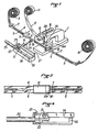
- the machine of the invention comprises a sewing machine 1, of any suitable type available commercially, which comprises a presser foot 2 movable under the effect of automatic internal members between a raised position where this foot is on Figure 1 and a low stitching position.
- Each closure 5 has a terminal end 7 which precedes an interval 6 .
- the entire strip 4 is guided by guide means of which only two are shown and designated by the references 8 and 9 in FIG. 1. These guide means pass the strip 4 under the presser foot 2 and direct it up to 'to a means of winding 10 this strip on itself which therefore moves in the direction indicated by an arrow F while passing through the sewing machine 1.
- the guide means 8 comprises a detector 8A at the end of each slider closure 5; when the latter have metal stapling elements, the detector is of the magnetic type: It is this detector 8A which controls the succession of operations which will be described later.
- the guide means 9 it is advantageous for the guide means 9 to comprise an end of strip 4 detector, for example an optical detector, intended to stop the machine when the strip 4 comes to an end.
- a ribbon supply means 11 is installed above the strip 4 of slider closures. This supply means 11 provides a ribbon 12 which descends towards the sewing machine 1 and towards the upper face of the band 4.
- the tape 12 passes between the cutting blades 14,15.
- This clamp 17 is carried by an element 19 movable in rotation which comprises a jack 20, one end of which the piston rod is provided with the clamp 17 while the opposite end is provided with a toothed wheel 21.
- the latter meshes with a rack 22 which is part of a means 23 for translational drive of the element 19 and clamp 17.
- This means 23 comprises a slide 24 which carries the rack 22 and which is connected to the piston rod of a jack 25.
- the latter, the slide 24 and the rack 22 are arranged in a plane parallel to the strip 4 of the closures 5 but the slide 24 and the actuator 19 are guided in translation by slides 26, 27 respectively which are inclined.
- the inclination is chosen so that the clamp 17 occupies a first position at which it is upstream of the cutting member 13 at the level of the tape 12 above the strip 4 and a second position at which the same clamp 17 is downstream of the presser foot 2 and rests on the upper face of the strip 4, or at least it is not far from this surface.
- the jack 20, the piston rod of which carries the clamp 17, has a stroke which enables it to give the latter, in the transverse direction to the ribbon 12, a first position at which this ribbon 12 is contained between the branches 18, and a second position at which branches 18 are set back relative to this same tape 12.
- a holding means 28 consisting of a jack arranged vertically and provided with a pad 29 capable of being applied against the strip 4, or more exactly as will be seen below, against the strip 12 resting on the strip 4 which itself rests on the plate of the to sew.
- the machine of the invention operates as follows.
- the strip 4 of successive slider closures 5 is wound by the winding means 10, which causes it to unwind from the unwinding means 3 passing in the direction F under the presser foot 2 and through the guide means 8, 9.
- the detector 8A detects the terminal end of a slider closure 5, it causes the movement of the strip 4 to stop.
- This detector is placed relative to the presser foot 2 so that, at the time of stop of the strip 4, the terminal end 7 is located just downstream of this same presser foot 2.
- the ribbon 12 is supplied by the supply means 11; the clamp 17 is pushed by the jack 20 to its first position at which the ribbon 12 is taken between the branches 18 upstream of the cutting member 13 whose movable blade 15 is in the open position.
- the jack 25 is actuated to push the slide 24.
- the rack 22 rotates the toothed wheel 21 and, consequently, the clamp 17.
- the length of the rack 22 is determined so that the toothed wheel 21 and the gripper 17 rotate only 180 °, after which the toothed wheel 21 is blocked by the end of the rack 22, the movable assembly 19 is driven in displacement above the strip 4 along an inclined path bringing it closer to it.
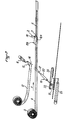
- the 180 ° rotation of the clamp 17 has folded clockwise the end portion 12A of the strip 12 and the displacement passes the branches 18 and the folded end portion 12A of the strip 12 between the open cutting blades 14, 15 of the cutting member 13.
- the displacement continues until the clamp 17 arrives at its second position where the folded end portion 12A rests on the strip 4 just behind the terminal end 7 of a slider closure S.
- the pad 29 of the holding means 28 is applied against the strip 12 and it holds it on the strip 4.
- the jack 20 pulls the clamp 17 to its second withdrawal position and the jack 25 retracts; the slider 24 returns to its initial position by carrying with it the clamp 17.
- the jack 20 carrying the clamp 17 arrives at the end of its return stroke and the rack 22 rotates the toothed wheel 21 and consequently, the clamp 17 by 180 ° counterclockwise which returns it to its first position.
- the jack 20 extends and the clamp 17 advances to again contain the ribbon 12.
- the latter being taken in the clamp 17 upstream of the cutting member 13 and clamped under the pad 29 upstream of the presser foot 2 , the actuator 16 actuates the cutting blade 15.
- the ribbon 12 is sectioned. Its new free end part remains retained in the clamp 17 upstream of the cutting member 13. Downstream of the latter, a long strand 12B extends as far as the presser foot 2 by covering the short strand 12A folded from below ; these two strands rest on the strip 4 of the slider closures.
- the presser foot 2 is lowered at the same time as the pad 29 is raised.
- the sewing machine 1 performs a transverse stitching 30 behind the fold which is located between the two strands 12A, 12B of the tape 12.
- This machine is equipped, as is common, with the members necessary for movement in the direction of stitching of the strip 4 and of the tape 12 under the presser foot 2.
- the means for guiding the strip 4 are designed to allow this transverse movement.
- the two parallel strips of the slide fastener are joined by a connecting tab. The length thereof is determined by the distance between the cutting member 13 and the sewing machine 1.
- the buffer 29 is not necessary; maintaining the ribbon 12 on the band 4 can be ensured by the presser foot 2 when the clamp 17 has fairly fine branches 18 or when the stitching can be made at a greater distance from the branches 18 of the clamp 17.
- the detector 8A of the terminal end 7 of the slider closures can be omitted when the pitch of these ends 7, on the strip 4, has a constant value.
Landscapes
- Engineering & Computer Science (AREA)
- Textile Engineering (AREA)
- Sewing Machines And Sewing (AREA)
- Slide Fasteners (AREA)
- Supports For Plants (AREA)
- Cable Accessories (AREA)
Claims (5)
Priority Applications (1)
| Application Number | Priority Date | Filing Date | Title |
|---|---|---|---|
| AT84401140T ATE33749T1 (de) | 1983-06-07 | 1984-06-05 | Maschine zum anbringen und befestigen von verbindungsteilen an reissverschlusstraegerbaendern. |
Applications Claiming Priority (2)
| Application Number | Priority Date | Filing Date | Title |
|---|---|---|---|
| FR8309416 | 1983-06-07 | ||
| FR8309416A FR2547176B1 (fr) | 1983-06-07 | 1983-06-07 | Machine pour la pose et la fixation de patte de jonction sur les rubans de fermeture a curseur |
Publications (3)
| Publication Number | Publication Date |
|---|---|
| EP0128100A2 EP0128100A2 (de) | 1984-12-12 |
| EP0128100A3 EP0128100A3 (en) | 1986-09-17 |
| EP0128100B1 true EP0128100B1 (de) | 1988-04-27 |
Family
ID=9289549
Family Applications (1)
| Application Number | Title | Priority Date | Filing Date |
|---|---|---|---|
| EP84401140A Expired EP0128100B1 (de) | 1983-06-07 | 1984-06-05 | Maschine zum Anbringen und Befestigen von Verbindungsteilen an Reissverschlussträgerbändern |
Country Status (4)
| Country | Link |
|---|---|
| EP (1) | EP0128100B1 (de) |
| AT (1) | ATE33749T1 (de) |
| DE (1) | DE3470658D1 (de) |
| FR (1) | FR2547176B1 (de) |
Families Citing this family (3)
| Publication number | Priority date | Publication date | Assignee | Title |
|---|---|---|---|---|
| JPH0714364B2 (ja) * | 1987-06-30 | 1995-02-22 | ワイケイケイ株式会社 | スライドフアスナ−端部への保護テ−プの供給,縫着方法および装置 |
| EP0339620B1 (de) * | 1988-04-28 | 1993-03-17 | DYNAT Gesellschaft für Verschlusstechnik und Feinmechanik mbH | Verfahren zum Herstellen von Querzugriegeln an Reissverschlüssen |
| CN112064215B (zh) * | 2020-09-23 | 2022-07-22 | 刘佳鸿 | 一种缝纫机 |
Family Cites Families (2)
| Publication number | Priority date | Publication date | Assignee | Title |
|---|---|---|---|---|
| DE1286796C2 (de) * | 1965-04-06 | 1976-09-23 | Opti-Werk Gmbh & Co, 4300 Essen | Verfahren zur herstellung von reissverschluessen |
| JPS5933367B2 (ja) * | 1979-03-05 | 1984-08-15 | ワイケイケイ株式会社 | 開離嵌插具付スライドフアスナ−用間歇フアスナ−チエ−ンの組合せ装置 |
-
1983
- 1983-06-07 FR FR8309416A patent/FR2547176B1/fr not_active Expired
-
1984
- 1984-06-05 AT AT84401140T patent/ATE33749T1/de not_active IP Right Cessation
- 1984-06-05 EP EP84401140A patent/EP0128100B1/de not_active Expired
- 1984-06-05 DE DE8484401140T patent/DE3470658D1/de not_active Expired
Also Published As
| Publication number | Publication date |
|---|---|
| FR2547176B1 (fr) | 1987-06-05 |
| EP0128100A3 (en) | 1986-09-17 |
| EP0128100A2 (de) | 1984-12-12 |
| DE3470658D1 (en) | 1988-06-01 |
| FR2547176A1 (fr) | 1984-12-14 |
| ATE33749T1 (de) | 1988-05-15 |
Similar Documents
| Publication | Publication Date | Title |
|---|---|---|
| CA1282683C (fr) | Dispositif de coupe perfectionne pour un appareil de distribution et de coupe simultanees de bandes de materiaux enroules | |
| LU83746A1 (fr) | Procede et appareil d'emballage de rouleaux avec dispositif d'insertion d'etiquettes | |
| FR2614271A1 (fr) | Machine de sanglage de paquet automatique. | |
| EP0080422B1 (de) | Maschine zum automatischen, zyklischen Zubinden von gefüllten oder leeren Behältnissen mittels eines Binddrahtes oder -fadens | |
| CH634531A5 (fr) | Procede et dispositif de bambanage de cable de filaments textiles. | |
| FR2706859A1 (de) | ||
| EP0128100B1 (de) | Maschine zum Anbringen und Befestigen von Verbindungsteilen an Reissverschlussträgerbändern | |
| FR2614578A1 (fr) | Machine pour la fabrication de conteneurs ou sacs en matiere thermoplastique | |
| FR2878241A1 (fr) | Machine automatique pour la formation d'un noeud a l'aide d'une ficelle en extremite d'une gaine tubulaire en vue de l'obturer par constriction sous l'effet du serrage du noeud | |
| EP0921074B1 (de) | Verfahren und Vorrichtung zum Zusammenfügen von ausgerichteten Gegenständen mittels Klebebändern | |
| CH616829A5 (en) | automatic machine for making a clove hitch with a cord around an object and use of the machine | |
| FR2586663A1 (fr) | Dispositif pour alimenter et couper une bande d'etiquettes | |
| FR2552408A1 (fr) | Dispositif de fixation de troncons de ruban sur des morceaux de tissu | |
| FR2518496A1 (fr) | Dispositif pour l'alimentation en etiquettes et vignettes analogues | |
| EP0004631B1 (de) | Verpackungsvorrichtung und -verfahren | |
| FR2609294A1 (fr) | Dispositif pour sectionner et positionner une chaine de points de couture formant un point de chainette sur du tissu avec une machine a coudre | |
| WO1989005368A1 (fr) | Dispositif pour l'insertion automatique d'une bande elastique plate dans les coins d'un drap-housse | |
| FR2772000A1 (fr) | Procede et dispositif pour reunir en lots des paquets en file continue au moyen de troncons de bandes adhesives | |
| EP0369898A1 (de) | Verfahren und Vorrichtung zur Herstellung von Schulterträgern für Bekleidung, insbesondere von Schulterträgern für Büstenhalter | |
| FR2806059A1 (fr) | Derouleuse pour gaine d'emballage equipee de moyens de coupe et de soudage et d'une bavette anti-retour | |
| FR2617514A1 (fr) | Dispositif pour positionner une chaine de points a coudre formant un point de chainette sur du tissu avec une machine a coudre | |
| FR2571753A1 (fr) | Machine pour l'engagement de longues pieces textiles plates, en particulier de draps, dans une secheuse-repasseuse, notamment une secheuse-repasseuse-plieuse | |
| FR2866017A1 (fr) | Dispositif d'assemblage de fils entre deux machines de traitement de fils. | |
| FR2588576A1 (fr) | Dispositif automatique de rentree de chainette pour machine a coudre du type surjeteuse a plusieurs fils | |
| FR91784E (de) |
Legal Events
| Date | Code | Title | Description |
|---|---|---|---|
| PUAI | Public reference made under article 153(3) epc to a published international application that has entered the european phase |
Free format text: ORIGINAL CODE: 0009012 |
|
| 17P | Request for examination filed |
Effective date: 19840618 |
|
| AK | Designated contracting states |
Designated state(s): AT BE CH FR GB IT LI LU NL SE |
|
| PUAL | Search report despatched |
Free format text: ORIGINAL CODE: 0009013 |
|
| AK | Designated contracting states |
Kind code of ref document: A3 Designated state(s): AT BE CH FR GB IT LI LU NL SE |
|
| 17Q | First examination report despatched |
Effective date: 19870206 |
|
| GRAA | (expected) grant |
Free format text: ORIGINAL CODE: 0009210 |
|
| AK | Designated contracting states |
Kind code of ref document: B1 Designated state(s): AT BE CH DE GB IT LI LU NL SE |
|
| PG25 | Lapsed in a contracting state [announced via postgrant information from national office to epo] |
Ref country code: NL Effective date: 19880427 Ref country code: IT Free format text: LAPSE BECAUSE OF FAILURE TO SUBMIT A TRANSLATION OF THE DESCRIPTION OR TO PAY THE FEE WITHIN THE PRESCRIBED TIME-LIMIT;WARNING: LAPSES OF ITALIAN PATENTS WITH EFFECTIVE DATE BEFORE 2007 MAY HAVE OCCURRED AT ANY TIME BEFORE 2007. THE CORRECT EFFECTIVE DATE MAY BE DIFFERENT FROM THE ONE RECORDED. Effective date: 19880427 Ref country code: AT Effective date: 19880427 |
|
| REF | Corresponds to: |
Ref document number: 33749 Country of ref document: AT Date of ref document: 19880515 Kind code of ref document: T |
|
| PG25 | Lapsed in a contracting state [announced via postgrant information from national office to epo] |
Ref country code: SE Effective date: 19880430 |
|
| REF | Corresponds to: |
Ref document number: 3470658 Country of ref document: DE Date of ref document: 19880601 |
|
| PG25 | Lapsed in a contracting state [announced via postgrant information from national office to epo] |
Ref country code: LU Free format text: LAPSE BECAUSE OF NON-PAYMENT OF DUE FEES Effective date: 19880630 Ref country code: LI Effective date: 19880630 Ref country code: CH Effective date: 19880630 |
|
| NLV1 | Nl: lapsed or annulled due to failure to fulfill the requirements of art. 29p and 29m of the patents act | ||
| GBV | Gb: ep patent (uk) treated as always having been void in accordance with gb section 77(7)/1977 [no translation filed] | ||
| PG25 | Lapsed in a contracting state [announced via postgrant information from national office to epo] |
Ref country code: GB Free format text: LAPSE BECAUSE OF NON-PAYMENT OF DUE FEES Effective date: 19881123 |
|
| BERE | Be: lapsed |
Owner name: SOC. NORMANDE DE CONFECTION Effective date: 19880630 |
|
| PLBE | No opposition filed within time limit |
Free format text: ORIGINAL CODE: 0009261 |
|
| STAA | Information on the status of an ep patent application or granted ep patent |
Free format text: STATUS: NO OPPOSITION FILED WITHIN TIME LIMIT |
|
| REG | Reference to a national code |
Ref country code: CH Ref legal event code: PL |
|
| 26N | No opposition filed | ||
| REG | Reference to a national code |
Ref country code: FR Ref legal event code: ST |
|
| PG25 | Lapsed in a contracting state [announced via postgrant information from national office to epo] |
Ref country code: BE Effective date: 19890630 |
|
| PG25 | Lapsed in a contracting state [announced via postgrant information from national office to epo] |
Ref country code: DE Effective date: 19900301 |