EP0128448A2 - Unité de propulsion et de direction amovible pour fauteuil roulant à propulsion par le malade - Google Patents
Unité de propulsion et de direction amovible pour fauteuil roulant à propulsion par le malade Download PDFInfo
- Publication number
- EP0128448A2 EP0128448A2 EP84106093A EP84106093A EP0128448A2 EP 0128448 A2 EP0128448 A2 EP 0128448A2 EP 84106093 A EP84106093 A EP 84106093A EP 84106093 A EP84106093 A EP 84106093A EP 0128448 A2 EP0128448 A2 EP 0128448A2
- Authority
- EP
- European Patent Office
- Prior art keywords
- chair
- main frame
- coupling
- frame
- wheel
- Prior art date
- Legal status (The legal status is an assumption and is not a legal conclusion. Google has not performed a legal analysis and makes no representation as to the accuracy of the status listed.)
- Withdrawn
Links
- 230000008878 coupling Effects 0.000 claims abstract description 39
- 238000010168 coupling process Methods 0.000 claims abstract description 39
- 238000005859 coupling reaction Methods 0.000 claims abstract description 39
- 238000010276 construction Methods 0.000 claims description 6
- 230000005484 gravity Effects 0.000 claims description 2
- 230000004048 modification Effects 0.000 abstract description 4
- 238000012986 modification Methods 0.000 abstract description 4
- 230000002452 interceptive effect Effects 0.000 abstract 1
- 210000002105 tongue Anatomy 0.000 description 4
- 239000004677 Nylon Substances 0.000 description 2
- 239000000463 material Substances 0.000 description 2
- 229910052751 metal Inorganic materials 0.000 description 2
- 229920001778 nylon Polymers 0.000 description 2
- 238000009434 installation Methods 0.000 description 1
- 239000002184 metal Substances 0.000 description 1
- 238000000034 method Methods 0.000 description 1
- 230000002441 reversible effect Effects 0.000 description 1
Images


Classifications
-
- A—HUMAN NECESSITIES
- A61—MEDICAL OR VETERINARY SCIENCE; HYGIENE
- A61G—TRANSPORT, PERSONAL CONVEYANCES, OR ACCOMMODATION SPECIALLY ADAPTED FOR PATIENTS OR DISABLED PERSONS; OPERATING TABLES OR CHAIRS; CHAIRS FOR DENTISTRY; FUNERAL DEVICES
- A61G5/00—Chairs or personal conveyances specially adapted for patients or disabled persons, e.g. wheelchairs
- A61G5/04—Chairs or personal conveyances specially adapted for patients or disabled persons, e.g. wheelchairs motor-driven
- A61G5/047—Chairs or personal conveyances specially adapted for patients or disabled persons, e.g. wheelchairs motor-driven by a modular detachable drive system
-
- A—HUMAN NECESSITIES
- A61—MEDICAL OR VETERINARY SCIENCE; HYGIENE
- A61G—TRANSPORT, PERSONAL CONVEYANCES, OR ACCOMMODATION SPECIALLY ADAPTED FOR PATIENTS OR DISABLED PERSONS; OPERATING TABLES OR CHAIRS; CHAIRS FOR DENTISTRY; FUNERAL DEVICES
- A61G5/00—Chairs or personal conveyances specially adapted for patients or disabled persons, e.g. wheelchairs
- A61G5/10—Parts, details or accessories
- A61G5/1051—Arrangements for steering
-
- A—HUMAN NECESSITIES
- A61—MEDICAL OR VETERINARY SCIENCE; HYGIENE
- A61G—TRANSPORT, PERSONAL CONVEYANCES, OR ACCOMMODATION SPECIALLY ADAPTED FOR PATIENTS OR DISABLED PERSONS; OPERATING TABLES OR CHAIRS; CHAIRS FOR DENTISTRY; FUNERAL DEVICES
- A61G2203/00—General characteristics of devices
- A61G2203/70—General characteristics of devices with special adaptations, e.g. for safety or comfort
- A61G2203/72—General characteristics of devices with special adaptations, e.g. for safety or comfort for collision prevention
- A61G2203/723—Impact absorbing means, e.g. bumpers or airbags
Definitions
- the present invention is especially directed to a motorized power unit which may be coupled to a conventional occupant-propelled type wheelchair to motorize the chair when desired, and which may be readily uncoupled from the chair when not needed.
- the present invention is especially directed to a power unit which may be readily coupled and uncoupled to and from most models of conventional occupant-propelled wheelchairs by the occupant, and which requires no modification of the wheelchair frame.
- the mechanism for mounting or coupling the power unit to the wheelchair takes the form of a pair of coupling brackets which may be clamped to the tubular frame members of the wheelchair by means of U bolts which pass around the tubular frame member and clamp the coupling brackets in fixed position upon the chair frame.
- This manner of mounting accommodates the mounting brackets to nearly all models of conventional occupant-propelled wheelchairs in that the brackets may be mounted on convenient frame members.
- One salient requirement of the installation is that the coupling pins carried by the brackets end up in a horizontal position above the front wheels of the chair.
- One coupling bracket is mounted at each side of the chair with the coupling pins in coaxial alignment with each other.
- the power unit itself includes a fixed frame upon which a single, steerable, power-driven wheel is mounted.
- the fixed frame of the power unit includes a pair of rearwardly extending handles which may be grasped by the occupant of the wheelchair to couple or uncouple the power unit.
- each handle Near its rearward end, each handle carries a channel member having a downwardly opening recess which is adapted to receive the coupling pin mounted upon the wheelchair.
- a manually operable latch on each handle is employed to lock the handles of the power unit to the coupling pins on the wheelchair, while permitting the fixed frame of the power unit to pivot relative to the wheelchair about the horizontal axis of the coupling pins.
- the fixed frame of the power unit includes a front bumper which, when rested on the ground, provides a stable support for the uncoupled power unit in a forwardly tilted position in which the handles on the fixed frame are necessarily approximately at the level of the arms of a conventional wheelchair so that they may be readily grasped by the occupant of the wheelchair when coupling or uncoupling the unit.
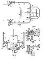
- a power unit designated generally 10 is shown respectively coupled to, and uncoupled from a wheelchair designated generally 12.
- Wheelchair 12 is of conventional construction and may take the form of any of several commercially available, occupant-propelled wheelchairs. Such chairs are almost invariably constructed with a pair of side frames F, made up of tubular metal elements such as 14, supported by large side wheels W and castered side wheels W-l, the side frames being spanned by a seat S and having arm rests A.
- Power unit 10 includes a fixed frame designated generally 16 which, as best seen in Figures 3 and 4, includes a pair of vertical side frame members 18, a top cross frame member 20 and a front bumper 22, all of these last elements being fixedly and rigidly secured to each other.
- a battery supporting tray 24 is fixedly mounted upon top cross frame member 20 to support an electric battery B.
- the fixed frame of the power unit also includes two handle units 26 which, apart from being right and left-handed, are of identical construction.
- Handle units 26 are of tubular metal construction and are fixedly clamped to the underside of the top cross frame member 20 by U bolts 28, this particular interconnection enabling the transverse spacing between the tube handle units 26 to be adjusted as required by the width of the wheelchair to which the unit is to be coupled.
- a motor-driven wheel assembly designated generally 30, is steerably mounted upon fixed frame 16, the unit 30 including an electric motor M, powered by battery B.
- this motor is a variable speed reversible motor of conventional construction which drives the wheel 32 in rotation via a belt and pulley or chain and sprocket drive indicated at 34.
- Unit 30 may be steered by a steering column 36 in a conventional manner, and suitable motor controls, not shown, of conventional construction may be located on the handlebar 38 fixed to the top of steering column 36.
- FIG. 1 the rearward ends of handle units 26 are bent upwardly and forwardly as at 40 and provided with handle grips G disposed laterally adjacent to frames F at a predetermined level relative to portions 26.
- a channel-shaped bracket 42 is fixedly mounted to the underside of handle 26 as by bolts 44 to project rearwardly from the handle.
- Channel members 42 are of an inverted U-shaped cross-section with vertically extending side walls 42a ( Figures 4, 5 and 6) integrally joined by a generally horizontal upper wall 46 ( Figure 5).
- upper wall 46 of channel-shaped member 42 is extended beyond the rearward ends of side walls 42a and bent downwardly as at 48 to form a downwardly opening recess 50 (see particularly Figure 2) at the rearward end of each channel-shaped member 42.
- a latch member 52 of nylon or another suitable material, is slidably mounted between the opposed side walls 42a of each member 42.
- a manually operated latch actuator 54 is slidably mounted on top of upper web 46 and is coupled to latch member 52 by a pair of bolts 56 which pass downwardly through a slot 58 in upper web 46.
- Latch member 52 has a rearwardly projecting tongue 60 with an inclined wedge face 60a.
- Latch tongue 60 may be selectively positioned to extend across the lower end of recess 50, as shown in full line in Figure 5, or alternatively may be moved to the left from the full line position of Figure 5 to the broken line position x clear of recess 50.
- the recess and latch are employed to couple power unit 10 to coupling brackets, designated generally 62, mounted on wheelchair 12.
- Coupling brackets 62 consist of a channel-shaped member having a pair of side webs 64, 66 ( Figure 6) which are integrally connected by a cross web 68.
- a rigid coupling pin 70 (of nylon or another suitable material) is fixedly secured to, and extends between, the opposed side webs 64, 66.
- Brackets 62 are mounted, in a semi-permanent manner, upon suitably located frame members 14 of the wheelchair 12, to locate the coupling pins 70 in horizontal coaxial alignment with each other at opposite sides of the chair.
- Brackets 62 may be secured to the tubular frame members 14 of the wheelchair by U-bolts 72, it being apparent that this manner of mounting will enable the brackets 62 to be mounted either to a horizontal wheelchair frame member as shown, or to a vertical member, as long as the coupling pin 70 is accessible from above either through one end, or the open side, of the channel-shaped bracket 62.
- the brackets 62 as shown in Figure 2, could equally well be mounted upon the vertical frame member of the wheelchair with pins 70 being located in substantially the same position as shown in Figure 2.
- power unit 10 is shown in an uncoupled, vertically tilted, stored position in which the unit is stably supported by wheel 22 and the engagement of bumper 22 with the floor.
- the upwardly bent portions 40 of handle units 26 are at approximately the same level as that of the armrests A of the wheelchair 12, and it is believed apparent that a handicapped person seated in wheelchair 12 who may not be able to bend from the waist can grasp the portions 40 of handles 26 with very little effort.
- the center of gravity c.g., instead of lying substantially in a vertical plane y through the wheel axis is disposed forwardly thereof, as shown in Figure 2, and it is the offset weight of battery b, in this position, which is responsible for this.
- the latch actuators 54 are pushed to their forward position so that the latch tongues 60 are withdrawn clear of recesses 50, as indicated in Figure 2.
- the occupant of the wheelchair then positions the chair in alignment with power unit 10 and by grasping the two handle portions 40, the occupant lowers the rear or left-hand end of the power unit frame downwardly until coupling pins 70 on the wheelchair are seated in the pin-receiving recesses 50.
- Latch actuators 54 are then pulled rearwardly by the occupant to move the latch tongues 60 to the position shown in Figure 5 in which the coupling pins 70 are trapped within the coupling recesses 50 on the power unit.
- Uncoupling of the unit is accomplished by reversal of the foregoing procedure.
Landscapes
- Health & Medical Sciences (AREA)
- Life Sciences & Earth Sciences (AREA)
- Animal Behavior & Ethology (AREA)
- General Health & Medical Sciences (AREA)
- Public Health (AREA)
- Veterinary Medicine (AREA)
- Handcart (AREA)
- Automatic Cycles, And Cycles In General (AREA)
Applications Claiming Priority (2)
| Application Number | Priority Date | Filing Date | Title |
|---|---|---|---|
| US06/503,524 US4503925A (en) | 1983-06-13 | 1983-06-13 | Detachable steerable power unit for occupant-propelled wheelchairs |
| US503524 | 1983-06-13 |
Publications (2)
| Publication Number | Publication Date |
|---|---|
| EP0128448A2 true EP0128448A2 (fr) | 1984-12-19 |
| EP0128448A3 EP0128448A3 (fr) | 1986-03-05 |
Family
ID=24002450
Family Applications (1)
| Application Number | Title | Priority Date | Filing Date |
|---|---|---|---|
| EP84106093A Withdrawn EP0128448A3 (fr) | 1983-06-13 | 1984-05-29 | Unité de propulsion et de direction amovible pour fauteuil roulant à propulsion par le malade |
Country Status (2)
| Country | Link |
|---|---|
| US (1) | US4503925A (fr) |
| EP (1) | EP0128448A3 (fr) |
Cited By (10)
| Publication number | Priority date | Publication date | Assignee | Title |
|---|---|---|---|---|
| EP0318677A1 (fr) * | 1987-10-08 | 1989-06-07 | Wimmer-Heusch, Friederike | Mécanisme d'entraînement manuel pour fauteuils roulants |
| US4944359A (en) * | 1988-07-28 | 1990-07-31 | Doman Trevor D | Vehicle and method of releasably coupling parts of the vehicle together |
| GB2227462A (en) * | 1988-11-16 | 1990-08-01 | Sunrise Medical Ltd | Vehicle |
| FR2642721A1 (fr) * | 1989-01-13 | 1990-08-10 | Flowers Michael | Vehicule personnel convertible comportant un chassis en plusieurs elements |
| DE4107410A1 (de) * | 1990-03-09 | 1991-09-12 | Reinhold Dipl Ing Stricker | Abnehmbares antriebs- und lenkaggregat fuer rollstuhl |
| DE4305592A1 (en) * | 1992-02-29 | 1993-09-16 | Sasse Maschinen Und Apparateba | Tractor coupled to wheelchair - has pair of wheels with differential driven by battery-powered motor with coupling to second pair of wheels |
| US6766871B2 (en) | 2002-06-27 | 2004-07-27 | George S. Sawyer | Attachment means for attaching a wheelchair to a motorized apparatus |
| ITUB20156827A1 (it) * | 2015-12-11 | 2017-06-11 | Smdm Srl Soluzioni Mecc Domotiche Meccatroniche | Dispositivo per la motorizzazione di carrozzine per disabili |
| ITUA20161666A1 (it) * | 2016-03-15 | 2017-09-15 | Tiboda S R L | Dispositivo per l'attacco rapido di una carrozzella ad un'unita' motrice |
| CN108243606A (zh) * | 2015-11-11 | 2018-07-03 | K·丹尼尔 | 用于轮椅的附接件 |
Families Citing this family (45)
| Publication number | Priority date | Publication date | Assignee | Title |
|---|---|---|---|---|
| US4708219A (en) * | 1986-05-09 | 1987-11-24 | Cresswell Thomas A | Disassemblable sulky for attachment to a steerable front wheel assembly condition |
| US5333702A (en) * | 1990-07-30 | 1994-08-02 | Ortho-Kinetics, Inc. | Three wheel scooter with quick release rear motor and wheel assembly |
| US5222567A (en) * | 1991-04-26 | 1993-06-29 | Genus Inc. | Power assist device for a wheelchair |
| US5494126A (en) * | 1994-06-02 | 1996-02-27 | Meeker; Galen L. | Apparatus and method for attaching a motorized wheel to a wheelchair |
| US6186252B1 (en) | 1996-07-03 | 2001-02-13 | Pride Mobility Products, Corporation | Foldable midwheel drive power chair |
| US6129165A (en) | 1996-07-03 | 2000-10-10 | Pride Mobility Products, Corporation | Curb-climbing power wheelchair |
| US6050593A (en) * | 1997-04-30 | 2000-04-18 | Golden Technologies, Inc. | Personal mobility vehicle |
| US6176337B1 (en) | 1997-04-30 | 2001-01-23 | Golden Technologies, Inc. | Personal mobility vehicle |
| US6729421B1 (en) * | 2000-06-06 | 2004-05-04 | Kaback Enterprises Inc. | Motor-assist gurney unit and method |
| GB0103280D0 (en) * | 2001-02-12 | 2001-03-28 | Pdq Mobility Ltd | Wheelchair mobility unit |
| US6611975B1 (en) | 2001-02-23 | 2003-09-02 | Roy D. Ricketts | Motorized bed assembly |
| GB0126989D0 (en) * | 2001-11-09 | 2002-01-02 | Sinclair Clive M | Wheelchair drive unit |
| TW530644U (en) * | 2002-07-12 | 2003-05-01 | Simon Chu | Detachable transmission mechanism for a wheel chair and a driving device thereof |
| US6889784B2 (en) * | 2003-01-24 | 2005-05-10 | Donald E. Troll | Motorized chariot |
| US7174093B2 (en) * | 2004-04-27 | 2007-02-06 | Midamerica Electronics Corporation | Wheel chair drive apparatus and method |
| US7117967B2 (en) * | 2004-04-27 | 2006-10-10 | Kidd William W | Wheel chair apparatus and method |
| US7216728B2 (en) * | 2004-07-02 | 2007-05-15 | Chao-Kuo Huang | Motorized apparatus for towing a wheelchair |
| US7267347B2 (en) * | 2004-10-12 | 2007-09-11 | Chien Ti Enterprise Co., Ltd. | Structural assembly for electric scooter |
| US20060131084A1 (en) * | 2004-12-22 | 2006-06-22 | Fred Rupp | Motorized handle |
| US7493977B1 (en) | 2005-02-15 | 2009-02-24 | Terry Ewert | Motorized chariot |
| US20070018443A1 (en) * | 2005-07-19 | 2007-01-25 | John Wilmot | Off-road wheelchair |
| US7735847B2 (en) * | 2007-06-19 | 2010-06-15 | Dougherty Patrick S | All terrain adapter for a wheelchair |
| US7871088B2 (en) * | 2007-12-18 | 2011-01-18 | José Silva | Cargo cart for wheeled mobility device |
| US20090152826A1 (en) * | 2007-12-18 | 2009-06-18 | Jose Freitas Silva | Cargo cart with hitch for wheeled mobility device |
| EP2535090B1 (fr) * | 2011-06-15 | 2018-04-18 | EWR Aktiengesellschaft | Unité d'entraînement pouvant être couplée |
| DE102012203084B4 (de) * | 2012-02-29 | 2015-04-02 | Rehability Reha-Fachhandel Gmbh & Co. Kg | Adaptierbarer Antrieb für einen Rollstuhl |
| DE102013105187A1 (de) * | 2013-05-21 | 2014-11-27 | Andreas Golz | Vorsatzantrieb für einen Rollstuhl |
| ES1089834Y (es) * | 2013-07-08 | 2013-12-13 | Batec Mobility S L | Dispositivo de seguridad para un elemento auxiliar de silla de ruedas |
| US9365254B1 (en) * | 2014-01-09 | 2016-06-14 | Richard Leo Durrett | Mobility scooter |
| USD805004S1 (en) | 2015-07-01 | 2017-12-12 | Amigo Mobility International, Inc. | Brake release handle |
| USD786741S1 (en) | 2015-11-16 | 2017-05-16 | Amigo Mobility International, Inc. | Lateral stability wheel |
| USD800410S1 (en) | 2015-11-23 | 2017-10-17 | Amigo Mobility International, Inc. | Material handling cart |
| USD955685S1 (en) | 2015-11-23 | 2022-06-21 | Amigo Mobility International, Inc. | Material handling cart |
| ITUA20162334A1 (it) * | 2016-04-06 | 2017-10-06 | Klaxon Mobility Gmbh | Gruppo di connessione per l’accoppiamento di un sistema ausiliario di trazione a una carrozzina per disabili |
| US11155147B2 (en) * | 2016-07-15 | 2021-10-26 | Ford Global Technologies, Llc | Auxiliary power device |
| US10625114B2 (en) | 2016-11-01 | 2020-04-21 | Icon Health & Fitness, Inc. | Elliptical and stationary bicycle apparatus including row functionality |
| KR101978667B1 (ko) * | 2017-12-20 | 2019-05-21 | 주식회사 로보쓰리 | 전동주행 전환용 휠체어 동력장치 |
| US10751232B1 (en) * | 2018-05-18 | 2020-08-25 | Erwin Ilao | Mobile application-controlled undercarriage |
| KR102158013B1 (ko) * | 2018-06-28 | 2020-09-21 | 주식회사 로보쓰리 | 전동주행 전환용 휠체어 동력장치 |
| US12090101B2 (en) * | 2018-07-23 | 2024-09-17 | INDIAN INSTITUTE OF TECHNOLOGY MADRAS (IIT Madras) | Extended wheelchair and an attachment device for the wheelchair |
| IT201800010144A1 (it) * | 2018-11-08 | 2020-05-08 | Pandhora | Unità di propulsione elettrica universale per carrozzine. |
| US12310900B2 (en) * | 2020-10-19 | 2025-05-27 | James Leroy King | Tractor driven assisted mobility system, device and method |
| US12533272B2 (en) | 2021-12-20 | 2026-01-27 | Permobil, Inc. | Self-aligning collapsible front add-on for a wheelchair |
| US12502320B2 (en) | 2021-12-20 | 2025-12-23 | Permobil, Inc. | System to adjust drive operation and performance in response to detection of a front add-on for a wheelchair |
| IT202200009368A1 (it) * | 2022-05-06 | 2023-11-06 | Klaxon Mobility Gmbh | Dispositivo ausiliario di trazione per sedie a rotelle per disabili |
Family Cites Families (24)
| Publication number | Priority date | Publication date | Assignee | Title |
|---|---|---|---|---|
| US678122A (en) * | 1899-11-23 | 1901-07-09 | Lowell M Maxham | Traction-motor. |
| US1565719A (en) * | 1923-02-14 | 1925-12-15 | Dunkley William Henry | Perambulator or baby carriage |
| US2468801A (en) * | 1947-02-07 | 1949-05-03 | Charles T Beall | Power operated chair |
| US2448992A (en) * | 1947-06-16 | 1948-09-07 | Love Homer | Propelling power unit for invalid wheel chairs |
| US2495573A (en) * | 1948-10-13 | 1950-01-24 | Duke Samuel | Motor attachment for wheel chairs |
| US2635703A (en) * | 1950-05-19 | 1953-04-21 | Norman V Grimes | Wheel chair adapted for optional operation by power or manually |
| US2649309A (en) * | 1951-06-08 | 1953-08-18 | Douglas D Deissner | Foldable wheel chair and steerable wheel attachment therefor |
| US2710659A (en) * | 1952-04-04 | 1955-06-14 | Moederle Vasco | Wheel chair and tractor combination |
| US2919756A (en) * | 1956-03-02 | 1960-01-05 | Earl A Knipe | Riding mower |
| US2978053A (en) * | 1957-10-21 | 1961-04-04 | Arthur O Schmidt | Driving and steering apparatus for wheel chairs |
| US2993550A (en) * | 1958-05-09 | 1961-07-25 | Aidco | Prime mover for wheel chairs |
| US3100547A (en) * | 1960-06-30 | 1963-08-13 | Rosenthal Harry | Electric driving apparatus for a wheel chair |
| GB1087225A (en) * | 1963-10-08 | 1967-10-18 | George Charles Leigh | Improvements in steering arrangements of invalid chalrs |
| FR1475405A (fr) * | 1965-04-09 | 1967-03-31 | Fauteuil roulant à moteur | |
| US3387681A (en) * | 1966-02-14 | 1968-06-11 | Rodney R. Rabjohn | Power operated wheel chair |
| FR1540324A (fr) * | 1967-03-06 | 1968-09-27 | Dispositif moteur et directeur adaptable à un fauteuil d'handicapé physique, pour réaliser une voiturette | |
| GB1197909A (en) * | 1967-07-03 | 1970-07-08 | Rodney R Rabjohn | Power Operated Wheel Chair |
| GB1401961A (en) * | 1971-04-01 | 1975-08-06 | Cusheon M P | Motorised vehicular assemblies |
| US3794132A (en) * | 1972-08-16 | 1974-02-26 | Lakeside Mfg Inc | Self-propelled wheelchair |
| GB1463500A (en) * | 1973-06-09 | 1977-02-02 | Cragg H | Wheelchairs |
| JPS5214502B2 (fr) * | 1973-07-27 | 1977-04-22 | ||
| US3912032A (en) * | 1973-11-26 | 1975-10-14 | Benz Vehicle Corp | Wheelchair-attachable powered unit |
| US3921774A (en) * | 1974-10-31 | 1975-11-25 | Donald H Hagen | Gear unit with disconnect clutch |
| US4386672A (en) * | 1981-06-11 | 1983-06-07 | Coker Theodore R | Detachable electric drive unit for wheelchair |
-
1983
- 1983-06-13 US US06/503,524 patent/US4503925A/en not_active Expired - Fee Related
-
1984
- 1984-05-29 EP EP84106093A patent/EP0128448A3/fr not_active Withdrawn
Cited By (13)
| Publication number | Priority date | Publication date | Assignee | Title |
|---|---|---|---|---|
| EP0318677A1 (fr) * | 1987-10-08 | 1989-06-07 | Wimmer-Heusch, Friederike | Mécanisme d'entraînement manuel pour fauteuils roulants |
| US4944359A (en) * | 1988-07-28 | 1990-07-31 | Doman Trevor D | Vehicle and method of releasably coupling parts of the vehicle together |
| GB2227462A (en) * | 1988-11-16 | 1990-08-01 | Sunrise Medical Ltd | Vehicle |
| GB2227462B (en) * | 1988-11-16 | 1993-02-10 | Sunrise Medical Ltd | Vehicle |
| FR2642721A1 (fr) * | 1989-01-13 | 1990-08-10 | Flowers Michael | Vehicule personnel convertible comportant un chassis en plusieurs elements |
| DE4107410C2 (de) * | 1990-03-09 | 1999-10-21 | Reinhold Stricker | Abnehmbares Antriebs- und Lenkaggregat für Rollstuhl |
| DE4107410A1 (de) * | 1990-03-09 | 1991-09-12 | Reinhold Dipl Ing Stricker | Abnehmbares antriebs- und lenkaggregat fuer rollstuhl |
| DE4305592A1 (en) * | 1992-02-29 | 1993-09-16 | Sasse Maschinen Und Apparateba | Tractor coupled to wheelchair - has pair of wheels with differential driven by battery-powered motor with coupling to second pair of wheels |
| US6766871B2 (en) | 2002-06-27 | 2004-07-27 | George S. Sawyer | Attachment means for attaching a wheelchair to a motorized apparatus |
| CN108243606A (zh) * | 2015-11-11 | 2018-07-03 | K·丹尼尔 | 用于轮椅的附接件 |
| ITUB20156827A1 (it) * | 2015-12-11 | 2017-06-11 | Smdm Srl Soluzioni Mecc Domotiche Meccatroniche | Dispositivo per la motorizzazione di carrozzine per disabili |
| ITUA20161666A1 (it) * | 2016-03-15 | 2017-09-15 | Tiboda S R L | Dispositivo per l'attacco rapido di una carrozzella ad un'unita' motrice |
| WO2017158504A1 (fr) * | 2016-03-15 | 2017-09-21 | Moretti S.P.A. | Dispositif pour a connexion rapide d'un fauteuil roulant à une unité motrice |
Also Published As
| Publication number | Publication date |
|---|---|
| EP0128448A3 (fr) | 1986-03-05 |
| US4503925A (en) | 1985-03-12 |
Similar Documents
| Publication | Publication Date | Title |
|---|---|---|
| US4503925A (en) | Detachable steerable power unit for occupant-propelled wheelchairs | |
| US4961473A (en) | Kit for converting a hand-powered wheelchair to an electric motor-power wheelchair | |
| US5291959A (en) | Individual vehicle usable in a manual or a motorized version, in particular a wheelchair or a tricycle | |
| EP1416896B1 (fr) | Chaise roulante et son système de fixation des roues | |
| US4199036A (en) | Wheel chair | |
| US3524512A (en) | Self-propelled driving and steering truck for shopping carts | |
| US5156226A (en) | Modular power drive wheelchair | |
| US5363771A (en) | Motorized portable system for aiding persons in ascending or descending stairways | |
| US4848504A (en) | Convertible walking/riding golf cart | |
| US5050695A (en) | Power attachment for wheelchair | |
| EP0145278B1 (fr) | Fauteuil roulant | |
| US2978053A (en) | Driving and steering apparatus for wheel chairs | |
| US4993732A (en) | Detachable manual propulsion system | |
| US3099326A (en) | Powered vehicle | |
| US5531284A (en) | Powered wheelchair with a detachable power drive assembly | |
| US4305601A (en) | Shopping cart for the handicapped | |
| US5927730A (en) | Scooter cart | |
| US20160244120A1 (en) | Bicycle with motor assisted folding | |
| US20240293273A1 (en) | Motorized accessory for a wheelchair | |
| US20020088657A1 (en) | Method and apparatus for motorizing a wheelchair | |
| EP0369791B1 (fr) | Véhicule | |
| US4209073A (en) | Collapsible four wheel electric powered vehicle | |
| EP0592427B1 (fr) | Chaise roulante comportant un dispositf d'actionnement et dispositif d'actionnement pour chaise roulante | |
| KR102309270B1 (ko) | 전후방 전환용 안장 프레임 장착식 휠체어 | |
| WO2013052778A1 (fr) | Module d'entraînement pour une chaise roulante |
Legal Events
| Date | Code | Title | Description |
|---|---|---|---|
| PUAI | Public reference made under article 153(3) epc to a published international application that has entered the european phase |
Free format text: ORIGINAL CODE: 0009012 |
|
| AK | Designated contracting states |
Designated state(s): BE DE NL |
|
| RAP1 | Party data changed (applicant data changed or rights of an application transferred) |
Owner name: MOBILITY MANUFACTURING CO. |
|
| PUAL | Search report despatched |
Free format text: ORIGINAL CODE: 0009013 |
|
| AK | Designated contracting states |
Kind code of ref document: A3 Designated state(s): BE DE NL |
|
| STAA | Information on the status of an ep patent application or granted ep patent |
Free format text: STATUS: THE APPLICATION IS DEEMED TO BE WITHDRAWN |
|
| 18D | Application deemed to be withdrawn |
Effective date: 19861107 |
|
| RIN1 | Information on inventor provided before grant (corrected) |
Inventor name: PALMER, JAMES A. Inventor name: GROMAK, STEPHEN C. |